EP0496593A2 - Anschlussstruktur für ein optisches Element - Google Patents
Anschlussstruktur für ein optisches Element Download PDFInfo
- Publication number
- EP0496593A2 EP0496593A2 EP92300532A EP92300532A EP0496593A2 EP 0496593 A2 EP0496593 A2 EP 0496593A2 EP 92300532 A EP92300532 A EP 92300532A EP 92300532 A EP92300532 A EP 92300532A EP 0496593 A2 EP0496593 A2 EP 0496593A2
- Authority
- EP
- European Patent Office
- Prior art keywords
- optical fiber
- single mode
- mode optical
- cylindrical member
- terminal structure
- Prior art date
- Legal status (The legal status is an assumption and is not a legal conclusion. Google has not performed a legal analysis and makes no representation as to the accuracy of the status listed.)
- Withdrawn
Links
Images

Classifications
-
- G—PHYSICS
- G02—OPTICS
- G02B—OPTICAL ELEMENTS, SYSTEMS OR APPARATUS
- G02B6/00—Light guides; Structural details of arrangements comprising light guides and other optical elements, e.g. couplings
- G02B6/24—Coupling light guides
- G02B6/26—Optical coupling means
- G02B6/264—Optical coupling means with optical elements between opposed fibre ends which perform a function other than beam splitting
-
- G—PHYSICS
- G02—OPTICS
- G02B—OPTICAL ELEMENTS, SYSTEMS OR APPARATUS
- G02B6/00—Light guides; Structural details of arrangements comprising light guides and other optical elements, e.g. couplings
- G02B6/24—Coupling light guides
- G02B6/26—Optical coupling means
- G02B6/262—Optical details of coupling light into, or out of, or between fibre ends, e.g. special fibre end shapes or associated optical elements
Definitions
- This invention relates to a terminal structure for an optical device, and more particularly to, a terminal structure for an optical device including a short-length optical fiber of single mode for connecting optical fibers optically.
- a conventional terminal structure for an optical device includes a short-length optical fiber of up to several tens mm fixed in a ferrule having an inside diameter slightly larger than a diameter of optical fibers to be connected through the terminal structure.
- the short-length optical fiber has a normalized frequency V in operation state of approximately 2.7 at a wavelength of 1.3 ⁇ m which is equivalent to a single mode fiber with no bending loss used as a long-length optical transmission path.
- the normalized frequency V is inversely proportional to the wavelength ⁇ , directly proportional to the radius a, and approximately proportional to square root of the relative difference between the two refractive indexes, that is ⁇ .
- the transmission light has a single mode when the normalized frequency V in operation state is under 2.405, and has LP 01 and LP 11 modes (linearly polarized modes 01 and 11) when the normalized frequency V is equal to or over 2.405 and under 3.83.
- the short-length optical fiber of the terminal structure has two misaligned joints with the connected optical fibers, LP 01 mode which is a transmission mode already existing in the optical fiber device into LP 11 mode and LP 01 mode at the first misaligned joint.
- the two modes are propagated in the short-length optical fiber, and are divided LP 0 1 mode and LP 11 mode again at the second misaligned joint LP 0 1 mode which is divided from LP 11 mode and the LP 0 1 mode which is propergated through the short length fiber interferes each other.
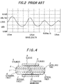
- connection efficiency at the second misaligned joint has the periodical characteristic of wavelength dependency in the transmission loss.
- a wavelength periodical dependency in the transmission loss may cause changes of the transmission loss by a slight change of a wavelength in use.
- the change of the tranmsission loss is affected by a misaligned degree of the joints or direction change thereof. Consequently, a slight change of the wavelength or phase of the light source is converted to a change of a light intensity by the terminal structure, so that noises are generated in the light signal.
- a terminal structure for an optical device comprises: a single mode optical fiber having a short length; and a cylindrical member in which the single mode optical fiber is fixed, the cylindrical member having the co-axis as that of a core of the single mode optical fiber, and each of both facets of the cylindrical member being polished to have a mirror surface; wherein the core and a clad of the single mode optical fiber have refractive indexes so that a normalized frequency in operation state of the single mode optical fiber becomes at most 2.405 as a value converted at a wavelength in use of 1.28 ⁇ m.
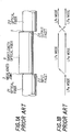
- a short-length single mode optical fiber 11 having input and output facets 23 and 24 is connected with optical fibers 21 and 22 to inevitably provide misaligned joints 3.
- the cutoff frequency of the normalized frequency V in operation state of the short-length single mode optical fiber 11 is approximately 2.7 at a wavelength of 1.3 ⁇ m, so that LP 11 mode is generated at the input facet 23 in addition to LP01 mode which is a transmission mode already existing in the optical fiber 21.
- the divided mode LP 11 is divided inevitably provide at the output facet 24 because of the misaligned joint.
- a short-length single mode optical fiber 1 is connected with optical fibers 21 and 22 with misaligned joints 3.
- the cutoff frequency of the normalized frequency V in operation state of the short-length single mode optical fiber 1 is under 2.405 at a wavelength of 1.28 ⁇ m, so that only LP01 mode exists at a wavelength in the range of 1.28 ⁇ m to 1.33 ⁇ m which is in practical use generally (1.31 ⁇ m in practice). Therefore, the optical loss generated at the misaligned joints 3 become radiation mode, so that the light may not reach the output facet 24. Consequently, there is no interference by occurence of LP 11 mode, so that there is no wavelength periodical dependency in the transmission loss.
- the optical fixed attenuator includes a short-length single mode optical fiber 1 having a characteristic explained above, and a capillary tube 4 in which the short-length single mode optical fiber 1 is fixed.
- the capillary tube 4 is fixed in a cylinder 5.
- the outer surface of the capillary tube 4 is processed so that the capillary tube 4 has the co-axis with a core center of the short-length single mode optical fiber 1.
- An external facet 6 of the optical terminal structure is optically polished so as to connect with an optical fiber for transmission, while an internal facet 7 has a predetermined angle to the right angle.
- a pair of cylinder units each including the short-length single mode optical fiber 1, the capillary tube 4 and the cylinder 5 are fixed to face each other with the internal facets 7 by a sleeve 9.
- An attenuation membrane 10 is sandwiched between the internal facets 7 of the two cylinder units.
- the optical fixed attenuator is connected with optical connectors at the external facets 6.
- the transmission loss may not change by the wavelength change or phase change of the light source caused by temperature changes.
- the transmission loss corresponds to the sum of the losses of the two misaligned joints, so that the change of the transmission loss due to the connection and disconnection process is as little as that in a conventional optical connector.
- the center wavelength in use is set to be 1.31 ⁇ m, however, the center wavelength in use may be changed by determining the refractive index n1 or the radium a in accordance with the formula (1). However, it is not preferable to change the refractive index n 1 , because a reflecting light is generated at the joint by the index difference when the optical terminal structure is connected with a conventional single mode optical fiber. If the refractive index of the core of the short-length optical fiber is 1.46 and non-refractive index difference is 0.003 which is equal to a conventional one, the core radius can be determined to be approximately 4.4 ⁇ m in case of the center wavelength in use of 1.31 ⁇ m.
- a single mode optical fiber to be connected with the optical terminal structure generally has a core radius of approximately 5 ⁇ m, so that the difference of the radius of the two optical fibers is not so small to be negligible.
- the optical density in the outer area in the cross-section of the optical fibers is relatively small, so that the optical loss by the radium difference at the joint can be ignored practically.
Landscapes
- Physics & Mathematics (AREA)
- General Physics & Mathematics (AREA)
- Optics & Photonics (AREA)
- Optical Couplings Of Light Guides (AREA)
- Optical Fibers, Optical Fiber Cores, And Optical Fiber Bundles (AREA)
- Light Guides In General And Applications Therefor (AREA)
- Mechanical Coupling Of Light Guides (AREA)
Applications Claiming Priority (2)
| Application Number | Priority Date | Filing Date | Title |
|---|---|---|---|
| JP21354/91 | 1991-01-23 | ||
| JP3021354A JPH04238307A (ja) | 1991-01-23 | 1991-01-23 | 光デバイス端末 |
Publications (2)
| Publication Number | Publication Date |
|---|---|
| EP0496593A2 true EP0496593A2 (de) | 1992-07-29 |
| EP0496593A3 EP0496593A3 (en) | 1993-07-28 |
Family
ID=12052766
Family Applications (1)
| Application Number | Title | Priority Date | Filing Date |
|---|---|---|---|
| EP19920300532 Withdrawn EP0496593A3 (en) | 1991-01-23 | 1992-01-22 | Terminal structure for an optical device |
Country Status (5)
| Country | Link |
|---|---|
| US (1) | US5257335A (de) |
| EP (1) | EP0496593A3 (de) |
| JP (1) | JPH04238307A (de) |
| AU (1) | AU649193B2 (de) |
| CA (1) | CA2059861C (de) |
Families Citing this family (9)
| Publication number | Priority date | Publication date | Assignee | Title |
|---|---|---|---|---|
| US5370649A (en) * | 1991-08-16 | 1994-12-06 | Myriadlase, Inc. | Laterally reflecting tip for laser transmitting fiber |
| JP3119751B2 (ja) * | 1992-12-02 | 2000-12-25 | 住友電気工業株式会社 | 光フィルタ |
| WO1996004580A1 (en) * | 1994-07-29 | 1996-02-15 | The Whitaker Corporation | Optical attenuator having a partially reflective surface |
| JP2921462B2 (ja) * | 1996-01-11 | 1999-07-19 | 日本電気株式会社 | 光コネクタ |
| JP3825930B2 (ja) * | 1999-01-28 | 2006-09-27 | ヒロセ電機株式会社 | 光コネクタ |
| US6253017B1 (en) * | 1999-08-04 | 2001-06-26 | Delphi Technologies, Inc. | Fiber optic connector with optical attenuator |
| CA2324193C (en) | 2000-10-25 | 2008-05-06 | Itf Optical Technologies Inc.-Technologies Optiques Itf Inc. | Internal termination for optical fibers |
| JP2010078704A (ja) * | 2008-09-24 | 2010-04-08 | Mitsubishi Cable Ind Ltd | 光ファイバの接続構造 |
| JP6151131B2 (ja) * | 2013-08-22 | 2017-06-21 | 株式会社フジクラ | 光ファイバの接続方法、及び、これに用いる光ファイバ接続装置 |
Family Cites Families (8)
| Publication number | Priority date | Publication date | Assignee | Title |
|---|---|---|---|---|
| US4205901A (en) * | 1975-07-17 | 1980-06-03 | International Standard Electric Corporation | Limited mode optical fiber |
| EP0096511B1 (de) * | 1982-06-05 | 1989-08-23 | AMP INCORPORATED (a New Jersey corporation) | Verfahren zum Anschliessen einer optischen Fiber, Anschluss, Spleiss und Stecker dazu |
| JPS60176003A (ja) * | 1984-02-22 | 1985-09-10 | Nippon Telegr & Teleph Corp <Ntt> | 光固定減衰器 |
| JPS63229409A (ja) * | 1987-03-18 | 1988-09-26 | Matsushita Electric Ind Co Ltd | 発光・受光モジユ−ル |
| JPS6465506A (en) * | 1987-09-04 | 1989-03-10 | Seiko Instr & Electronics | Optical attenuator |
| GB2229829B (en) * | 1989-03-31 | 1993-03-17 | Philips Nv | A connector for a fibre optic cable |
| US5082345A (en) * | 1990-08-13 | 1992-01-21 | At&T Bell Laboratories | Optical fiber connecting device including attenuator |
| JP2633073B2 (ja) * | 1990-09-07 | 1997-07-23 | 株式会社精工技研 | 可変型光減衰器 |
-
1991
- 1991-01-23 JP JP3021354A patent/JPH04238307A/ja active Pending
-
1992
- 1992-01-22 CA CA002059861A patent/CA2059861C/en not_active Expired - Fee Related
- 1992-01-22 EP EP19920300532 patent/EP0496593A3/en not_active Withdrawn
- 1992-01-23 US US07/824,078 patent/US5257335A/en not_active Expired - Fee Related
- 1992-01-23 AU AU10428/92A patent/AU649193B2/en not_active Ceased
Also Published As
| Publication number | Publication date |
|---|---|
| AU1042892A (en) | 1992-07-30 |
| EP0496593A3 (en) | 1993-07-28 |
| AU649193B2 (en) | 1994-05-12 |
| CA2059861C (en) | 1998-05-05 |
| US5257335A (en) | 1993-10-26 |
| JPH04238307A (ja) | 1992-08-26 |
| CA2059861A1 (en) | 1992-07-24 |
Similar Documents
| Publication | Publication Date | Title |
|---|---|---|
| CA1311381C (en) | Connector employing mode field modification | |
| JP2572402B2 (ja) | 光ファイバ回線のアクセス方法及びそのコネクタプラグ | |
| EP0192164B1 (de) | Optische Kupplungsvorrichtung | |
| US4199222A (en) | Optical device with a laser-to-fiber coupler | |
| US4213677A (en) | Light coupling and branching device using light focusing transmission body | |
| US5499309A (en) | Method of fabricating optical component including first and second optical waveguide chips having opposed inclined surfaces | |
| KR900006003B1 (ko) | 반사를 감소시키는 광에너지 전송장치 | |
| CA2047374C (en) | Optical fiber connecting device including attenuator | |
| US4893889A (en) | Optical attenuator | |
| US5497438A (en) | Optical transmission and reception module having coupled optical waveguide chips | |
| EP0725289A2 (de) | Steckerstift mit vier polarisationserhaltenden optischen Fasern und dessen Kupplungsgehäuse | |
| US3933410A (en) | Optical connector with single scrambling volume | |
| EP0496593A2 (de) | Anschlussstruktur für ein optisches Element | |
| JP3888942B2 (ja) | 光ファイバ部品 | |
| US5822478A (en) | Optical device with means for preventing remaining scattered light rays from being fed back to the signal line and method for fabricating it | |
| US4867517A (en) | Fail-safe acousto-optic T-couplers for optical communication networks | |
| KR100361441B1 (ko) | 탭 커플러 | |
| JP2865789B2 (ja) | 光伝送モジュール | |
| US6882774B2 (en) | Wavelength division multiplexing coupler | |
| US5166514A (en) | Optical plug system for optical measuring device | |
| US6826319B2 (en) | Optical isolator | |
| JPH05203829A (ja) | ループバック光コネクタ装置 | |
| JPH0425804A (ja) | 光学接続構造 | |
| JPH09159862A (ja) | 光ファイバコネクタ | |
| US20250004204A1 (en) | System for coupling a multi-core optical fiber with at least one single-core optical fiber, and corresponding coupling method |
Legal Events
| Date | Code | Title | Description |
|---|---|---|---|
| PUAI | Public reference made under article 153(3) epc to a published international application that has entered the european phase |
Free format text: ORIGINAL CODE: 0009012 |
|
| 17P | Request for examination filed |
Effective date: 19920214 |
|
| AK | Designated contracting states |
Kind code of ref document: A2 Designated state(s): DE FR GB |
|
| PUAL | Search report despatched |
Free format text: ORIGINAL CODE: 0009013 |
|
| AK | Designated contracting states |
Kind code of ref document: A3 Designated state(s): DE FR GB |
|
| 17Q | First examination report despatched |
Effective date: 19950412 |
|
| 18D | Application deemed to be withdrawn |
Effective date: 20020917 |