EP0496684A1 - Vorrichtung zur gleichzeitigen Nassbehandlung von mehreren Proben und ihre Verwendung - Google Patents
Vorrichtung zur gleichzeitigen Nassbehandlung von mehreren Proben und ihre Verwendung Download PDFInfo
- Publication number
- EP0496684A1 EP0496684A1 EP19920420024 EP92420024A EP0496684A1 EP 0496684 A1 EP0496684 A1 EP 0496684A1 EP 19920420024 EP19920420024 EP 19920420024 EP 92420024 A EP92420024 A EP 92420024A EP 0496684 A1 EP0496684 A1 EP 0496684A1
- Authority
- EP
- European Patent Office
- Prior art keywords
- application cavity
- cavity
- container
- application
- axis
- Prior art date
- Legal status (The legal status is an assumption and is not a legal conclusion. Google has not performed a legal analysis and makes no representation as to the accuracy of the status listed.)
- Granted
Links
Images




Classifications
-
- B—PERFORMING OPERATIONS; TRANSPORTING
- B01—PHYSICAL OR CHEMICAL PROCESSES OR APPARATUS IN GENERAL
- B01J—CHEMICAL OR PHYSICAL PROCESSES, e.g. CATALYSIS OR COLLOID CHEMISTRY; THEIR RELEVANT APPARATUS
- B01J19/00—Chemical, physical or physico-chemical processes in general; Their relevant apparatus
- B01J19/08—Processes employing the direct application of electric or wave energy, or particle radiation; Apparatus therefor
- B01J19/10—Processes employing the direct application of electric or wave energy, or particle radiation; Apparatus therefor employing sonic or ultrasonic vibrations
-
- G—PHYSICS
- G01—MEASURING; TESTING
- G01N—INVESTIGATING OR ANALYSING MATERIALS BY DETERMINING THEIR CHEMICAL OR PHYSICAL PROPERTIES
- G01N1/00—Sampling; Preparing specimens for investigation
- G01N1/28—Preparing specimens for investigation including physical details of (bio-)chemical methods covered elsewhere, e.g. G01N33/50, C12Q
- G01N1/44—Sample treatment involving radiation, e.g. heat
-
- B—PERFORMING OPERATIONS; TRANSPORTING
- B01—PHYSICAL OR CHEMICAL PROCESSES OR APPARATUS IN GENERAL
- B01J—CHEMICAL OR PHYSICAL PROCESSES, e.g. CATALYSIS OR COLLOID CHEMISTRY; THEIR RELEVANT APPARATUS
- B01J19/00—Chemical, physical or physico-chemical processes in general; Their relevant apparatus
- B01J19/08—Processes employing the direct application of electric or wave energy, or particle radiation; Apparatus therefor
- B01J19/12—Processes employing the direct application of electric or wave energy, or particle radiation; Apparatus therefor employing electromagnetic waves
- B01J19/122—Incoherent waves
- B01J19/126—Microwaves
-
- H—ELECTRICITY
- H05—ELECTRIC TECHNIQUES NOT OTHERWISE PROVIDED FOR
- H05B—ELECTRIC HEATING; ELECTRIC LIGHT SOURCES NOT OTHERWISE PROVIDED FOR; CIRCUIT ARRANGEMENTS FOR ELECTRIC LIGHT SOURCES, IN GENERAL
- H05B6/00—Heating by electric, magnetic or electromagnetic fields
- H05B6/64—Heating using microwaves
- H05B6/80—Apparatus for specific applications
-
- H—ELECTRICITY
- H05—ELECTRIC TECHNIQUES NOT OTHERWISE PROVIDED FOR
- H05B—ELECTRIC HEATING; ELECTRIC LIGHT SOURCES NOT OTHERWISE PROVIDED FOR; CIRCUIT ARRANGEMENTS FOR ELECTRIC LIGHT SOURCES, IN GENERAL
- H05B6/00—Heating by electric, magnetic or electromagnetic fields
- H05B6/64—Heating using microwaves
- H05B6/80—Apparatus for specific applications
- H05B6/806—Apparatus for specific applications for laboratory use
-
- B—PERFORMING OPERATIONS; TRANSPORTING
- B01—PHYSICAL OR CHEMICAL PROCESSES OR APPARATUS IN GENERAL
- B01J—CHEMICAL OR PHYSICAL PROCESSES, e.g. CATALYSIS OR COLLOID CHEMISTRY; THEIR RELEVANT APPARATUS
- B01J2219/00—Chemical, physical or physico-chemical processes in general; Their relevant apparatus
- B01J2219/08—Processes employing the direct application of electric or wave energy, or particle radiation; Apparatus therefor
- B01J2219/12—Processes employing electromagnetic waves
- B01J2219/1203—Incoherent waves
- B01J2219/1206—Microwaves
- B01J2219/1209—Features relating to the reactor or vessel
-
- B—PERFORMING OPERATIONS; TRANSPORTING
- B01—PHYSICAL OR CHEMICAL PROCESSES OR APPARATUS IN GENERAL
- B01J—CHEMICAL OR PHYSICAL PROCESSES, e.g. CATALYSIS OR COLLOID CHEMISTRY; THEIR RELEVANT APPARATUS
- B01J2219/00—Chemical, physical or physico-chemical processes in general; Their relevant apparatus
- B01J2219/08—Processes employing the direct application of electric or wave energy, or particle radiation; Apparatus therefor
- B01J2219/12—Processes employing electromagnetic waves
- B01J2219/1203—Incoherent waves
- B01J2219/1206—Microwaves
- B01J2219/1209—Features relating to the reactor or vessel
- B01J2219/1212—Arrangements of the reactor or the reactors
- B01J2219/1218—Multiple reactors
-
- B—PERFORMING OPERATIONS; TRANSPORTING
- B01—PHYSICAL OR CHEMICAL PROCESSES OR APPARATUS IN GENERAL
- B01J—CHEMICAL OR PHYSICAL PROCESSES, e.g. CATALYSIS OR COLLOID CHEMISTRY; THEIR RELEVANT APPARATUS
- B01J2219/00—Chemical, physical or physico-chemical processes in general; Their relevant apparatus
- B01J2219/08—Processes employing the direct application of electric or wave energy, or particle radiation; Apparatus therefor
- B01J2219/12—Processes employing electromagnetic waves
- B01J2219/1203—Incoherent waves
- B01J2219/1206—Microwaves
- B01J2219/1209—Features relating to the reactor or vessel
- B01J2219/1221—Features relating to the reactor or vessel the reactor per se
- B01J2219/1224—Form of the reactor
- B01J2219/1227—Reactors comprising tubes with open ends
Definitions
- the present invention relates to an apparatus for carrying out a treatment in a humid environment simultaneously on a plurality of samples, the apparatus implementing microwave heating of the samples. Also part of the invention is the use of the apparatus for carrying out chemical reactions on samples which may be a mineral, organic or organometallic compound or a mixture of compounds.
- Such an apparatus effectively makes it possible to simultaneously process various samples under the same conditions of temperature and reaction time but does not allow easy access of the containers to the operator, for example to introduce an additional reagent or to monitor visually the progress of the reactions. To do this, the operator must, after stopping from the microwave generator, open the front door of the oven and access to the containers is not easy. In addition, in such an apparatus, the entire container is heated, in particular its neck, and not only the part containing the sample to be treated.
- An object of the invention is an apparatus for carrying out a treatment in a humid environment simultaneously on a plurality of samples.
- Another object of the invention is an apparatus for carrying out a treatment in a humid environment, the calories being provided by heating by means of microwaves, for which access to the containers containing the samples is particularly easy for the operator.
- an apparatus for treatment in a humid environment simultaneously on a plurality of samples, each treatment taking place in a container containing a sample characterized in that said apparatus comprises means for emitting microwaves into a microwave application cavity, the application cavity being a cylinder, delimited by an upper wall, a lower wall and a side wall and admitting an X axis, said cavity application having in its upper wall a plurality of openings, each opening having a size such that it allows the introduction of a container into the application cavity, each opening being provided with a chimney of a height H as a function of the frequency of emission of the microwaves and of the cross section of the opening to form an absorption barrier opposing the propagation of microwaves in the ex inside the application cavity.
- a sample placed in a container is subjected to microwaves to effect rapid heating thereof, for example to carry out a chemical reaction and / or a physical operation in a humid environment on the sample.
- chemical reactions such as mineralization, decomposition, hydrolysis ... or physical operations can be carried out such as dissolution, crystallization, evaporation, fusion ... or even combine on the same sample a physical operation and a chemical reaction.
- tubular containers it is also possible, as will be described below, to carry out treatments in a humid environment simultaneously on a succession of samples, samples of defined volume then being successively fed into each container by means of valves or else still the samples fed into each container being separated by gas bubbles (for example air), the samples separated by the bubbles being in the form of a continuous flow in the tubular container.
- gas bubbles for example air
- the application cavity is a cylinder whose director is an advantageously regular polygon.
- the application cavity is a regular cylinder whose director is a circle.
- the means for emitting the microwaves consist of at least one microwave generator whose antenna is located in the application cavity.
- such an apparatus comprises a microwave generator whose antenna is located in the application cavity along its axis X.
- the device which is the subject of the invention is such that the means for emitting microwaves in the application cavity are constituted by at least one assembly formed by a microwave generator emitting in a waveguide, the waveguide being in connection with the application cavity, and admitting an axis of symmetry Y parallel to the direction of movement of the microwaves in the waveguide.
- such an apparatus comprises at least one waveguide which has an axis of symmetry Y parallel to the axis X of the application cavity.
- such an apparatus comprises a waveguide whose axis of symmetry Y coincides with the axis X of the application cavity.
- such an apparatus comprises at least one waveguide which has an axis of symmetry Y orthogonal to the axis X of the application cavity.
- such an apparatus comprises at least one waveguide whose axis of symmetry Y is parallel to the axis X of the application cavity and at least one waveguide whose axis of symmetry Y is orthogonal to the X axis of the application cavity.
- the apparatus for treating in a humid environment which is the subject of the invention, can of course comprise both at least one microwave transmitter whose antenna is located in the application cavity and at least one assembly constituted by a microwave generator emitting in a waveguide.
- the apparatus according to the invention can comprise several assemblies constituted by a microwave generator emitting in a waveguide.
- the assemblies are arranged, with respect to the microwave application cavity, in such a way that the axes of symmetry of the waveguides orthogonal to the X axis of the application cavity are located in the same plane and are intersecting or parallel so that the openings of the waveguides in the side wall of the application cavity are offset.
- the assemblies are arranged relative to the microwave application cavity so that the axes of symmetry of the waveguides are located at different altitudes so that the openings of the waveguides waves in the side wall of the application cavity are offset.
- the axes of symmetry of the waveguides can be located in the same vertical plane and / or in parallel and / or intersecting vertical planes.
- the openings of the waveguides in the side wall of the application cavity are never face to face.
- the apparatus, object of the invention is such that for each assembly constituted by a microwave generator emitting in a waveguide, the waveguide and the application cavity admit the same vertical plane of symmetry containing the X axis of the application cavity.
- each waveguide is arranged relative to the application cavity so that its axis is perpendicular to the axis X of the application cavity.
- each waveguide can be arranged radially with respect to the application cavity or can be arranged perpendicular to a radial plane of the microwave application cavity .
- the openings in the upper wall of the application cavity are not arranged randomly but are arranged in at least one circle admitting as axis X the axis of the application cavity.
- the application cavity of the device according to the invention is such that the upper wall of the application cavity consists of an annular peripheral zone integral with the side wall and a central area with the openings.
- the removable central zone is circular and accepts the axis X of the application cavity as an axis.
- a circular central area can be rotated.
- the upper wall of the application cavity can be independent of the side wall and be driven in a rotational movement around the axis X of the application cavity.
- a circular central zone or an upper wall independent of the side wall makes it possible, when they are rotated around the axis X of the application cavity, to submit all the samples present in the containers to the same amount of microwave.
- the central zone or the upper wall can be rotated by any known means. They can be driven by friction by means of a rotating roller or a belt, they can also be driven by means of a toothed wheel or a chain, the central zone or the upper wall then being provided with cooperating means. with the roller or the belt or the toothed wheel or the chain.
- Such an arrangement brings a certain homogeneity of the distribution of the microwaves in the application cavity, even if the apparatuses according to the invention comprise, in a manner known per se, means of wave agitation, such than a wave brewer.
- the containers intended to contain the samples are made of a material permeable to microwaves, they are for example glass, plastic material ... Their shape is not critical, their dimensions are chosen so that they can penetrate the application cavity on the one hand, by the chimney, and on the other hand, by the opening of the upper wall of the application cavity.
- Containers with an elongated neck, such as test tubes, flasks, ampoules, usually used in the laboratory are well suited.
- the container in order to carry out, in at least one container, with the apparatus which is the subject of the invention, a treatment in a humid environment on a sample flowing in a continuous flow, or on a succession of samples, can be formed by a tube, open to its two ends to allow the continuous flow of the sample stream or the succession of samples.
- the container can consist of a helically wound tube, the characteristics of which have been determined so that the residence time of the sample in the application cavity is sufficient.
- the container neck is advantageously provided at its upper part with an external bead, intended to rest on the upper edge of the chimney in order to keep the container suspended. If the neck of the container does not have an external bead and / or if its section is smaller than the internal section of the chimney, an adapter can be placed between the neck and the chimney.
- the chimney is tubular, of cylindrical shape, of constant section. It rises over a height H chosen as a function of the passage section of the opening in the upper wall of the application cavity and the frequency of emission of the microwaves so as to constitute an absorption barrier opposing the propagation of microwaves outside the application cavity.
- the chimney provides, in addition to a microwave propagation barrier function, a container suspension function. If the neck of the container is too long with respect to the height H of the chimney, a spacer can be placed between the outer bead of the container and the upper edge of the chimney. The height of the spacer will of course be chosen so that the part of the container containing the sample is placed in the microwave application cavity.
- the chimney can be entirely located above the upper wall of the microwave application cavity, it can also be, at least in part, located inside the application cavity. However, in no case may the chimney have a height H less than the height H specified above.
- the chimney can be made of any conductive material put in continuous form such as a sheet, or put in discontinuous form such than a grid, a trellis, a fabric, a perforated sheet.
- each chimney is extended, at its part located in the application cavity, by a sheath permeable to microwaves and closed at its end. low, to avoid falling debris from the container and sample into the application cavity when a container ruptures.
- the sheath is independent of the chimney, thus, according to this embodiment in each chimney is placed a sheath permeable to microwaves, closed at its lower end, said sheath protruding from the chimney in the application cavity and comprising at its upper part a retaining means cooperating with the upper edge of the chimney.
- the container rests on the upper edge of the sheath directly or by means of an adapter.
- each chimney may include an annular chamber surrounding the chimney in its part situated above the upper wall of the application cavity, said chamber being provided with means fluid inlet and outlet.
- the fluid intended to circulate in the annular chamber is, for example, water.
- the device, object of the invention may include a plurality of plugs adaptable to each container opening, each plug having a passage connected to a suction means. and / or neutralization of the gaseous products emitted by the sample during the treatment.
- the caps can be plugs introduced into the necks of the containers or be made of elastic material and adapt to the necks of the containers externally.
- the tube can comprise, upstream with respect to the direction of flow, and in its part external to the chimney, a derivation intended for the adaptation of a stopper, as above, to the container.
- the apparatus which is the subject of the invention may be such that it includes means for animating at least one container with a rotational movement on itself, about an axis parallel to the X axis of the application cavity.
- the container can be rotated on itself by direct drive, for example by friction using a rotating roller or a driven belt and partially surrounding the container.
- the container can be rotated on itself by indirect drive, that is to say by rotating the sheath placed in the chimney or the chimney itself, the container resting on the edge top of the duct or chimney directly or by means of an adapter.
- the sheath or the chimney can be rotated directly, as above for the container, for example by friction.
- each container in order to carry out in each container a treatment in a humid environment on a succession of samples each container forms part of a circuit comprising a treatment chamber constituted by the container, and with reference to the direction of movement of the sample in the circuit, upstream of the processing chamber, a sample supply conduit, possibly a conduit for introducing at least one liquid which may be a reagent, a liquid supply conduit rinse, and, downstream of the treatment chamber, an outlet pipe for the treatment product, each pipe being provided with a valve.
- a sample supply duct possibly at least one introduction duct. of a liquid, for example a reagent and a supply line for rinsing liquid.
- a liquid for example a reagent and a supply line for rinsing liquid.
- conduits each being provided with a valve, can lead individually into the circuit, they can also be in parallel and connected to a common conduit which ensures the connection with the circuit.
- the device can comprise a single liquid introduction conduit, it can of course comprise, for example for carrying out chemical reactions, several introduction conduits of several reagents, these conduits can lead individually into the circuit, they can also be in parallel and connected to a common conduit which ensures the connection with the circuit.
- the rinsing liquid can be, for example water, it can also be the liquid used to carry out the treatment in a humid environment.
- the device which is the subject of the invention may comprise, upstream of the treatment chamber, a supply pipe for a standard, possibly fitted with a valve.
- This conduit can join the sample supply conduit downstream from its valve.
- a predetermined quantity of sample is fed into the circuit.
- the sampling line can thus include means for determining a volume or a mass of sample to be treated, in particular when the latter is in solid form.
- the apparatus according to the invention can be such that at least two containers are connected in series by a connector.
- the connector may include means for transferring the sample from one container to the other container, constituted for example by a pump.
- the connection between two containers can also include means for introducing a reagent into the sample transferred from one container to another.
- the apparatus, object of the invention can be intended to carry out a treatment in a humid environment on a continuous flow of sample.
- the apparatus is then such that the container is constituted by a tube open at its two ends and the lower wall of the application cavity further comprises a plurality of openings for the passage of the containers, each opening being provided with a chimney height H depending on the frequency of emission of the microwaves and of the passage section of the opening to form a microwave absorption barrier.
- An apparatus the container of which consists of a tube open at its two ends, is particularly intended for the production of apparatus of which at least two receptacles are connected in series.
- a first container will be connected by its lower part to the lower part of a second container by means of a connector and the second container will be connected by its upper part to the upper part of a third container by a another fitting and so step by step.
- the sample can circulate in the containers under the effect of pressure introduction means located upstream of the first container, or suction means located downstream of the last container traversed.
- the chimneys surrounding the openings located in the lower wall may be at least partially located inside the microwave application cavity.
- each container can be surrounded by a tubular sheath, the latter for example can rest at its upper part by a retaining means on the upper edge of the chimney located above the upper wall of the cavity d 'application, cross the application cavity, then the chimney located below the bottom wall of the application cavity.
- a sheath is of course made of material permeable to microwaves.
- the chimneys can be such that they comprise an annular chamber in their part situated below the lower wall of the cavity d application, the annular chamber being provided with fluid inlet and outlet means.
- the device can be such that the lower wall of the application cavity is, like the upper wall, constituted by an annular peripheral zone secured to the side wall and a central zone connected to the zone. center of the upper wall.
- the lower wall of the application cavity is independent of the side wall and is integral with the upper wall.
- the application cavity may, according to one embodiment of the apparatus which is the subject of the invention, internally have regularly distributed deflectors, substantially perpendicular to the upper and lower walls of the application cavity.
- the deflectors are, of course, made of material which is not permeable to microwaves.
- the deflectors are substantially planar and rectangular, the axis X of the cavity being located in their planes. According to this embodiment, the deflectors are arranged radially in the application cavity.
- the deflectors are cylindrical surfaces of generatrix parallel to the axis X of the application cavity and arranged so that the concave face of a deflector faces the convex face of the adjacent deflector , symmetrically with respect to a plane of symmetry containing the axis of a waveguide and the application cavity, the concave faces being turned towards the opening in the side wall of the application cavity of the guide d 'corresponding waves.
- the deflectors may be integral with the upper and / or lower walls and / or annular zones .
- the deflectors are integral with the side wall of the microwave application cavity.
- deflectors is more particularly intended for an apparatus comprising a microwave generator whose antenna is located in the application cavity along its axis X or for an apparatus which comprises a waveguide whose '' axis symmetry Y coincides with the axis X of the application cavity.
- Such deflectors each consist of a cylindrical generator wall parallel to the axis X of the application cavity, said wall substantially enveloping each container and having an opening along its part located towards the zone of the container opposite the axis. of the application cavity, two adjacent deflectors being connected by a connecting wall, the space between the deflectors, the connecting walls and the side wall of the application cavity being filled with a material impermeable to microwaves .
- the device which is the subject of the invention may be such that the means for emitting the microwaves do not emit the microwaves directly in the application cavity.
- the apparatus is then such that the means for emitting the microwaves emit the microwaves in a secondary cavity situated below the application cavity, the wall situated between the secondary cavity and the application cavity being provided with coupling windows.
- the coupling windows are located, in the wall between the application cavity and the secondary cavity, vertically of the containers placed in the application cavity.
- the apparatus can be such that the means for emitting the microwaves, emit the microwaves in a circular secondary cavity, of axis X, the upper wall of which is provided with a plurality coupling windows, arranged in at least one circle, each coupling window being surrounded by a chimney located above the upper wall of the secondary cavity, the interior space of the chimney forming an elementary application cavity of the microwave intended to receive the container, the chimneys being of a height H as a function of the frequency of emission of the microwaves in the secondary cavity and of the section of the coupling windows to oppose the propagation of the microwaves. waves out of the elementary cavities.
- the device may include means for monitoring the progress of the treatments.
- the control means can be constituted by measurement probes placed in each container within the sample, for example measuring the conductivity thereof.
- the apparatus for treating in a humid environment according to the invention can be controlled manually by an operator switching on the heating by microwaves and / or possibly maneuvering according to a predetermined cycle the various valves and / or the means of rotation.
- the apparatus comprises control means, such as a microprocessor, of the starting and stopping of the heating by microwave and possibly of the opening and the closing of the various valves and / or means of rotation.
- control means such as a microprocessor, of the starting and stopping of the heating by microwave and possibly of the opening and the closing of the various valves and / or means of rotation.
- All the parts of the apparatus for treating in a humid environment according to the invention, capable of being in contact with the samples are advantageously made of material resistant to corrosion, the reagents possibly used being particularly aggressive and the temperature reached in the high containers.
- material glass and polytetrafluoroethylene are generally well suited.
- the apparatus for treating in a humid environment which is the subject of the present invention is intended to submit samples contained in containers to microwaves in order to heat them quickly, this heating having the aim of carrying out a physical and / or chemical operation on the sample.
- the device is particularly intended to be used to carry out chemical reactions in a humid environment on samples. It is particularly intended for reactions such as the acid or alkaline treatment in a humid environment of samples for the purpose of dissolution, hydrolysis or mineralization.
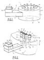
- Figure 1 is a schematic external general view of an embodiment of the wet-processing device according to the invention.
- FIG. 2 is a partial detail view of the device according to FIG. 1.
- Figure 3 is a detail view, in section, of the periphery of the upper wall of the application cavity of an apparatus according to Figures 1 and 2, the upper wall can be driven with a rotational movement.
- Figure 4 is a sectional view, through a diametrical plane, of another embodiment of the device object of the invention.
- Figure 5 is a general external view of an apparatus according to the invention, comprising a secondary cavity.
- Figure 6 is a detailed sectional view of an alternative connection of a waveguide to an application cavity.
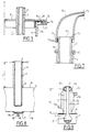
- Figure 7 is a detail view, in section through a vertical plane, of a plug associated with a chimney to capture the gaseous products of the reaction.
- Figure 8 is a sectional view, through a vertical plane, of an embodiment of a chimney and a container.
- Figure 9 is a sectional view, through a vertical plane, of another embodiment of a chimney and a container.
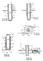
- Figures 10 and 11 are sectional views, through a vertical plane of two alternative embodiments of a chimney associated with a sheath and a container.
- FIG 12 is a detailed sectional view of an embodiment of the apparatus in which each chimney constitutes an elementary application cavity.
- FIG. 13 is a general external view of another embodiment of the apparatus for treating in a humid environment, object of the invention.
- FIG. 14 is a detailed view, in section, of the periphery of the application cavity of an apparatus according to FIG. 13, the central region of the upper wall of the application cavity can be moved of rotation.
- FIG. 15 is a schematic detail representation of an apparatus, object of the invention, making it possible to carry out in each container a treatment on a succession of samples.
- Figure 16 is a sectional view through a vertical plane of a container associated with two chimneys according to another embodiment of the apparatus of the invention.
- Figure 17 is a sectional view through a diametrical plane of an embodiment of the apparatus in which the containers are tubes.
- FIGS 18 and 19 are two schematic partial sectional views of two other embodiments of the apparatus of the invention, each container is a tube.
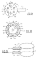
- Figures 20, 21, 22 are sectional views through a horizontal plane of three embodiments of an application cavity provided with deflectors.
- FIG. 23 is schematically an overall view of an embodiment of an apparatus comprising three assemblies constituted by a microwave generator emitting in a waveguide, the application cavity of which is of hexagonal section and which has a central area animated by a rotational movement.
- Figure 24 is a block diagram of an embodiment of the means for animating the containers with a rotational movement on themselves.
- FIG. 25 is diagrammatically an overall view of another embodiment of an apparatus, according to the invention, comprising two assemblies constituted by a microwave generator emitting in a waveguide.
- the processing apparatus (1) object of the invention, shown diagrammatically in FIG. 1, is intended to carry out a chemical reaction in a humid environment, simultaneously on a plurality of samples, each reaction taking place in a container (2), not shown in FIG. 1, containing the sample and at least one reagent, it will hereinafter be called "chemical reaction apparatus".
- the apparatus (1) comprises as means (50) for emitting microwaves a set (10) constituted by a generator (5) of microwaves emitting in a waveguide (6) and an application cavity (7) microwaves in connection with the waveguide (6).
- the application cavity (7) is, according to the present embodiment, a cylinder whose directrix is a circle and the assembly (10) is arranged in such a way that the waveguide (6) and the cavity d 'application (7) admit the same vertical plane of symmetry.
- the application cavity (7) is delimited by an upper wall (8), a lower wall (16) and a side wall (13). It admits an axis X which is according to the present embodiment orthogonal to the direction of movement of the microwaves in the waveguide (6).
- FIG. 2 is a partial view of the apparatus according to FIG. 1 showing four containers (21 to 24) placed in four openings (31 34) of the upper wall (8) of the application cavity (7).
- the device (1) shown in Figure 1 allows to introduce ten containers (2) in the application cavity (7).
- the containers (21 to 24) containing the samples and the reagents are introduced into the application cavity (7) and their heating is ensured by the microwaves emitted by the generator ( 5).
- the containers (21 to 24) are test tubes carrying a bead (9) outside the upper part of their neck (11).
- the upper wall (8) thereof has a plurality of openings (31 to 34), each opening (3) at a dimension such that it allows the introduction of a container (2) into the application cavity (7).
- the openings (31 to 34) in the upper wall (8) of the application cavity (7) are arranged in a circle having as axis the axis X of the application cavity (7).
- the openings (31 to 34) are arranged in a circle (shown in phantom), symmetrically with respect to the plane of symmetry of the waveguide (6) and, in this case, of the application cavity (7).
- Each opening (3) is provided with a chimney (4), located at its periphery, of a height H, function of the frequency of emission of the microwaves and of the passage section of the opening (3) , to form an absorption barrier opposing the propagation of microwaves outside the application cavity (7).
- the chimneys (41 to 44) are tubular, cylindrical in shape and made up of a sheet.
- the chimneys (41 to 44) are located partly in the application cavity (7). They can be formed of two sections welded one above and the other below the upper wall (8) of the application cavity (7) or else be in one piece the upper wall (8) will then be cut to put in place and weld the chimneys (41 to 44), the openings (31 to 34) are defined by the internal straight sections, located in the plane of the upper wall (8) of the application cavity (7) of the micro- waves, chimneys (41 to 44).
- the containers (2) are provided with necks (11) too long for the bead (9) to rest directly on the upper edge (40) of the chimneys (4), spacers (74) are then placed between the bead (9) containers (2) and the upper edge (40) of the chimneys (4). However, the spacers (74) are not too high so that the part (20) of the container (2) containing the sample and the reagent (s) is outside the bottom of the chimney (4).
- the chemical reaction apparatus (1) object of the invention, comprises means for agitating (15) microwaves constituted by a wave stirrer such as a fan, these means bring a certain homogeneity to the field. microwave in the application cavity (7).
- An apparatus (1) according to the embodiment described above, that is to say of which the application cavity (7) is cylindrical, can be such that the upper wall (8) is driven by a movement of rotation about the axis X of the application cavity (7), the upper wall (8) is independent of the side wall (13) of the application cavity (7).
- the containers (2) move around the axis of rotation X in a circle and are therefore all subject to the same microwave application conditions.
- the upper wall (8) of the application cavity (7) is then provided at its periphery on the one hand, with a ferrule (75) engaging in the application cavity (7) and on the other hand, means (76) which cooperate with means (77) carried by the side wall (13) of the application cavity (7) to constitute a quarter-wave trap (78) .
- the bottom wall (16) of the cavity d application (7) and the lower part of the side wall (13) also comprise means for constituting a quarter-wave trap, and, advantageously, the lower wall (16) is made integral with the upper wall (8) by example using members.
- the chemical reaction apparatus (1) object of the invention represented in section by a diametral plane in FIG. 4 comprises, like the apparatus represented in FIGS. 1 and 2, a cylindrical application cavity (7), of circular director, of axis X, delimited by an upper wall (8), a lower wall (16) and a side wall (13).
- the means (50) for emitting microwaves in the application cavity (7) consist of a generator (5) whose antenna (51) is located in the application cavity (7) along its axis X, the microwave generator (5) being below the bottom wall (16) of the application cavity (7).
- the device (1) shown allows, like the device (1) previously described, to introduce ten containers (2) into the application cavity (7), through openings (3) in the upper wall (8). , the openings (3) being arranged along a circle of axis X.
- Each opening (3) in the upper wall (8) of the application cavity (7) is provided with a chimney (4) located at its periphery, of cylindrical shape, of height H, depending on the emission frequency. microwaves and the passage section of the opening (3), to form an absorption barrier opposing the propagation of microwaves outside the application cavity (7).
- the chimneys (4) are partly located in the application cavity (7) and the containers (2) rest by the bead (9) of their neck (11) on the upper edge (40) of the chimneys (4).
- the apparatus for chemical reaction in a humid environment as shown in FIG. 5 comprises an application cavity (7) similar to that described above and a secondary cavity (14), located below the application cavity (7).
- the secondary cavity (14) is delimited by a lower wall (116), a side wall (113), in the extension of the side wall (13) of the application cavity (7), and an upper wall (16) which is the bottom wall of the application cavity (7).
- the secondary cavity (14) is therefore cylindrical and has the same axis X as the application cavity (7).
- the means (50) for emitting microwaves in the secondary cavity (14) consist of a generator (5) whose antenna (51) is located in the secondary cavity (14), along the axis X of that -ci, the generator (5) being placed below the bottom wall (116) of the secondary cavity (14).
- the wall (16) between the secondary cavity (14) and the application cavity (7) is provided with coupling windows (120) located vertically above the containers (2).
- the device (1) shown in FIG. 5, comprises four containers (21 to 24) in the form of a test tube, the closed end of which is placed in the vicinity of the wall (16) above the coupling windows (120).
- Each container (2) penetrates into the application cavity (7) through an opening (3) provided with a chimney (4), and rests by its bead (9) on the upper edge (40) of the chimney (4 ).
- Figure 6 is a detailed sectional view of the connection of a waveguide (6) to an application cavity (7), the waveguide (6) bringing the microwaves to the center of the lower wall (16) of the application cavity (7) through the opening (39) thereof, and being according to the embodiment shown perpendicular to the axis X of the application cavity (7).
- the waveguide (6) has its end (36) closed and has an opening (37) on its wall closest to the application cavity (7) corresponding to the opening (39) of the bottom wall (16).
- connection cone (49) diverging towards the cavity d application (7), welded on the one hand to the bottom wall (16) of the application cavity (7) and on the other hand to the wall of the waveguide (6).
- the container (2) In order to capture the fumes and / or vapors produced by the chemical reaction, the container (2), the upper part of the neck (11) of which is shown in FIG. 7, may include a plug (70) adapted to the opening (60) of the container (2).
- the stopper (70) is made of elastic material and adapts to the container (2).
- the stopper (70) is held by the cooperation of a flange (71) located at the upper end of the neck (11) of the container (2) and two ribs (72) located on the internal face of the stopper (70) , the two ribs (72) and the flange (71) seal.
- the plug (70) comprises a conduit (73) for evacuating smoke and / or vapors, which can be connected to suction and / or neutralization means.
- the neck (11) of the container (2) is provided externally with two ears (99), which like the bead (9) previously described, are intended to rest on the upper edge (40) of the chimney (4).
- the containers (2) have been described above open (for example Figures 2 and 3) or provided with a cap (70) intended for the capture of the fumes or vapors emitted (Figure 7), they can also be provided with a cap ensuring a tight closure of the container, the container then being constituted in such a way that it can withstand internal pressure.
- the chimney (4) is made of conductive material put in discontinuous form, it is here constituted by a wire mesh.
- the resistance of the wire mesh constituting the chimney (4) is however determined to have sufficient mechanical resistance so that the chimney (4), in addition to its function of microwave propagation barrier, can provide the support function of the container (2 ) by pressing the outer bead (9) on the upper edge (40) of the chimney (4).
- the chimney (4) is located at the periphery of the opening (3) of the upper wall (8) of the application cavity (7).
- the chimney (4) is all located above the upper wall (8) of the application cavity (7) and rises to a height H chosen as a function of the passage section of the opening (3) and the frequency of emission of the microwaves in order to constitute an absorption barrier opposing the propagation of microwaves outside the application cavity (7).
- the application cavity (7) comprises, in its lower wall (16) perpendicular to the opening (3), therefore, just below the container (2), a means of 'evacuation (79) of any product likely to be spread in the application cavity (7) by the breakage of the container (2).
- the discharge means (79) is, for example as shown, consisting of a bowl (17), produced by stamping the bottom wall (16) or added by welding, the bowl (17) having a hole (18) the diameter of which can be calculated so that it itself constitutes a microwave propagation barrier, or else a plug (19) can be provided to close the hole (18).
- the bowl (17) can also be removable, those skilled in the art will of course provide means for trapping microwaves between the bowl (17) and the bottom wall (16) of the application cavity (7). .
- the chimney (4) is located very above the upper wall (8) of the application cavity (7), it is made of conductive material of continuous structure, it is here constituted by a sheet formed into a tubular form and welded at the periphery of the opening (3) to the upper wall (8) of the application cavity (7).
- the opening (3) is of larger section than that of the neck (11) of the container (2) in order to allow the passage of the swollen part (20) of the container (2) intended to contain the sample and the reagent (s).
- the chimney (4) is surrounded by a sleeve (56) defining an annular chamber (52).
- the sleeve (56) comprises two pipes (53, 54) constituting means for the entry and exit of a circulating fluid, making it possible to regulate the temperature of the chimney (4) and thereby the temperature of the neck (11 ) of the container (2) depending on the chemical reaction carried out in the container (2).
- cooling the neck (11) of the container (2) can allow the condensation of the vapors emitted by the sample and the return of the condensate by gravity in the container (2).
- the height H of the chimney (4) is of course chosen according to the frequency of emission of the microwaves in the application cavity (7) and the dimension of the opening (3) in the upper wall ( 8) of the application cavity (7) in order to stop the propagation of microwaves towards the outside of the device (1).
- the outer section of the neck (11) of the container (2) is less than the internal section of the chimney (4), in order to be able to hold the container (2) in the device (1) there an adapter (55) is placed between the upper part of the neck (11) and the upper edge (40) of the chimney (4).
- the adapter (55) is frustoconical in order to be able to engage and be maintained in the chimney (11) and the bead (9) outside the container (2) rests on the adapter (55).
- the chimney (4) according to the embodiment shown, in section through a vertical plane, Figure 10 is located both above and below the upper wall (8) of the application cavity (7).
- the chimney (4) is extended in the application cavity (7) by a sheath (58), permeable to microwaves, intended to prevent the possible fall of the sample and of debris from the container (2) in the cavity application (7) when it breaks.
- a spacer (74) Between the bead (9) outside the container (2) and the upper edge (40) of the chimney (4) is interposed between the bead (9) outside the container (2) and the upper edge (40) of the chimney (4) is interposed a spacer (74).
- the height H of the chimney (4) is, of course, chosen as above in order to constitute a barrier to the propagation of microwaves out of the application cavity (7).
- the chimney (4) and the sheath (58) are independent.
- the sheath (58) rests by a retaining means such as a bead (59) on the upper edge (40) of the chimney (4) and the container (2) rests by its bead (9) on the bead (59 ) of the sheath (58).
- the chemical reaction apparatus (1) is such that the microwaves are emitted in a cylindrical secondary cavity (14), of axis X , the upper wall (29) of which is provided with a plurality of coupling windows (120) arranged along at least one circle of axis X, each coupling window (120) being surrounded by a chimney (4), located above the upper wall (29) of the secondary cavity (14), the chimney (4) being of cylindrical shape.
- the interior space of the chimney (4) forms a basic microwave application cavity (7) intended to receive the container (2).
- the chimney (4) is constituted in its lower part (46) by a discontinuous structure, such as a wire mesh and in its upper part (47) by a continuous structure such as a sheet. It has a height H as a function of the frequency of emission of the microwaves in the secondary cavity (14) and of the section of the coupling window (120) to oppose the propagation of the microwaves out of the elementary cavities (7).
- a sheath (58) which rests by the bead (59) on the upper edge (40) of the chimney (4).
- the container (2) rests by its lower part (30) on the bottom of the sheath (58) directly or after intercalation of a shock absorbing material.
- FIG. 13 comprises a cylindrical application cavity (7) and two assemblies constituted by a generator (not shown) emitting in a waveguide (61 or 62).
- Wave guides (61, 62) are arranged such that each waveguide (61 or 62) is perpendicular to a radial plane of the application cavity (7), and in order to maintain a certain symmetry, the axes of symmetry (Y1, Y2) of the waveguides (61, 62) are parallel.
- the axes of symmetry (Y1, Y2) of the waveguides (61, 62) can of course be at the same altitude or at different altitudes.
- the openings (121, 122) of the waveguides (61, 62) in the side wall (13) of the application cavity (7) are thus offset.
- the device (1) object of the invention, is such that the upper wall (8) of the application cavity (7) consists of an annular peripheral zone (48) integral with the side wall (13) of the application cavity (7) and of a central zone (38) comprising the openings (3) which are here distributed in two concentric circles.
- the openings (3) located closest to the X axis of the application cavity (7) have a smaller diameter than that of the openings (3) located along the outer circle, as well as containers (2) of different diameters can be placed in the application cavity (7).
- the openings (3) are of course provided with chimneys (not shown) as defined above.
- the central area (38) of an apparatus (1) is preferably removable and constitutes a sort of basket carrying the containers.
- the central zone (38) and the peripheral zone (48) are of course provided with means constituting a quarter-wave trap similar to that shown in FIG. 3.
- the central zone (38) of the upper wall (8) of the application cavity (7) is provided at its periphery with a ferrule (75) and means (76) which cooperate with means (77) carried by the peripheral zone (48) of the upper wall (8) to constitute a quarter-wave trap (78).
- the central zone (38) rests on the peripheral zone (48) by means of balls (94) placed in a groove (95) carried by the peripheral zone (48).
- the teeth (65) located on the external lateral face (90) of the quarter-wave trap (78) allows, thanks to a chain, the rotation drive of the central zone (38).
- the lower wall of the application cavity (7) is also formed a peripheral zone and a central zone similar to the zones (48, 38) of the upper wall.
- the central zone of the lower wall (16) is then made integral with the central zone (38) of the upper wall (8) for example using members.
- FIG. 15 is a schematic detail view of a container (2) and a chimney (4) placed in an application cavity (7).
- each container (2) is part of a circuit (80) comprising a treatment chamber, constituted by said container (2), placed in the application cavity (7).
- the opening (3) of the upper wall (8) of the application cavity (7) is of course as above provided with a chimney (4).
- the circuit (80) comprises, upstream of the treatment chamber, that is to say of the container (2), a conduit (82) d supply of samples, a conduit (83) for introducing at least one reagent, and a conduit (84) for supplying rinsing liquid. Downstream of the container (2) the circuit (80) has a conduit (85) for output of the treatment product.
- the pipe (82) for supplying samples, the pipe (83) for introducing at least one reagent and the pipe (84) for supplying rinsing liquid are respectively provided with valves (86, 87, 88 ).
- the conduit (83) for introducing at least one reagent can introduce into the circuit (80), a single reagent or successively several reagents or a mixture of at least two reagents, according to the needs of the chemical reaction.
- the conduit (85) for output of the treatment product is also provided with a valve (89).
- the valve (89) is intended to prevent the product from flowing out of the circuit (80) for the time necessary for the completion of the reaction in the container (2).
- the circuit (80) of the apparatus also has a duct called a vent (81) intended to put the interior space of the circuit (80) into communication with the atmosphere.
- the vent (81) allows, in particular, the gases, born of the chemical reaction, to escape outside the circuit (80).
- the sample supply conduit (82) is connected to a source of samples constituted for example by a sampling line coming from an installation.
- the rinsing liquid supply duct (84) is connected to a source of rinsing liquid.
- valves (86, 87, 88, 89) being closed beforehand, the valve (86) of the pipe (82) for supplying samples is opened and a predetermined quantity of sample is fed into the circuit (80) [operation a], upstream of the container (2), for example by means of a positive displacement pump. The valve (86) is then closed.
- valve (87) of the pipe (83) for introducing a reagent is opened and the desired amount of reagent is introduced into the circuit (80) [operation b], for example by means of a positive displacement pump, then close the valve (87).
- the sample and the reagent are therefore present in the container (2).
- the microwave generator is put into operation for a predetermined time and the container (2) placed in the microwave application cavity (7) is thus heated [operation c].
- valve (89) is then opened and the treatment product [operation d] is recovered via the outlet pipe (85), this leaving the circuit (80) under the effect of gravity.
- valve (88) of the line (84) for rinsing liquid supply is opened and the circuit is rinsed, [operation e], the soiled rinsing liquid leaving the circuit (80) via the conduit (85) is directed towards an effluent storage tank.
- Such an apparatus is advantageously controlled by a microprocessor.
- An apparatus (1) as described above may not include a valve (86) on the sample supply pipe (82), or a valve (89) on the product outlet pipe (85) of the treatment, the samples supplied by the conduit (82) then form a succession of samples separated by gas bubbles, the samples and the bubbles being in flow according to a continuous flow.
- the flushing operation (e) can be carried out during the passage of the gas bubble in the circuit.
- FIG 16 is a detail view in section through a vertical plane of an embodiment of the apparatus object of the invention, intended to carry out a chemical reaction on a continuous flow of sample.
- each container (2) of the device (1) consists of a tube passing through the application cavity and open at its two ends (68, 69), the container (2) can thus be connected d on the one hand by its end (68) to a supply line for the sample and possibly one or more reagents and on the other hand by its end (69) to an outlet for the product of the treatment.
- the container (2) enters the application cavity (7) through an opening (3) in the upper wall (8) and emerges through an opening (35) in the lower wall (16).
- the openings (3) and (35) are of course provided with chimneys (4) and (45) of a height H as a function of the frequency of the microwaves and of the passage section of the openings (4, 45) for form a microwave absorption barrier.
- the container (2) in the form of a tube is placed in a sheath (58) open at its two ends.
- the sheath (58) is provided with a retaining means (59) such as a bead by means of which it rests on the upper edge (40) of the chimney (4).
- the sheath (58) envelops the container (2) from the top of the chimney (4) to the bottom of the chimney (45) therefore throughout the passage of the application cavity (7). It is of course made of material permeable to microwaves.
- the device (1) shown schematically in FIG. 17 in section through a diametrical plane is an device (1) comprising twelve tubular containers (2), associated with chimneys (4, 45) in the vicinity of the upper (8) and lower ( 16), as shown in Figure 16.
- the microwave application cavity (7) is of course cylindrical with an X axis, the containers are arranged in a circle with an X axis, and the microwaves are emitted into the application cavity (7) by means (5) consisting of a generator (50) whose antenna (51) is located in the application cavity (7) along its axis X.
- the containers (21, 22, 23) on the one hand and the containers (24, 25, 26) on the other hand are connected in series by the connectors (111, 112) and (114, 115).
- the connector (115) between the containers (25) and (26) comprises means (117) for introducing a reagent into the sample transferred from the container (25) to the container (26).
- the sample circulates in the containers connected in series under the effect of the liquid supply pressure from the inlets E of the containers (21, 24) to the outlets S of the containers (23, 26).
- Such an apparatus can allow, like the apparatus shown in FIG. 16, the carrying out of a chemical reaction in a humid environment on a continuous flow of samples.
- the device (1) according to the invention, a schematic partial view of which is shown in FIG. 18, comprises several containers (2) each container (2) being constituted by a helically wound tube placed in the application cavity (7).
- the application cavity (7) has in its upper wall (8) and in its lower wall (16) openings (3, 35) for the passage of the container (2) to these openings (3, 35) are of course associated chimneys (4, 45) as defined above.
- the means (50) for emitting microwaves in the application cavity (7) consist of a generator (5) whose antenna (51) is located in the application cavity (7) along its axis X , the application cavity (7) being cylindrical and the plurality of containers (2) arranged along a circle of axis X.
- the containers (2) have their characteristics (internal diameter, diameter, pitch and number of turns of the propeller) which have been determined so that the residence time of the sample and of the reagent (s) in the application cavity ( 7) is sufficient.
- the container (2) comprises an inlet tube E for the sample and the reagent (s) and an outlet tube S for the treatment product.
- the apparatus (1) according to the embodiment of which a schematic partial view is shown in FIG. 19 comprises a cylindrical secondary cavity (14), of axis X, the upper (129) and lower (130) walls of which are provided with a plurality of coupling windows (120) arranged along at least one circle of axis X, the coupling windows (120) of the upper (129) and lower (130) walls being placed one above the other .
- Each coupling window (120) is surrounded by a chimney (4, 45), (4) for the chimney associated with the coupling window (120) of the upper wall (129), (45) for the chimney associated with the coupling window (120) of the bottom wall (130).
- the interior space of each chimney (4, 45) forms a basic microwave application cavity (7) intended to receive the container (21 or 22).
- Each container (21) or (22) consists of a helically wound tube, two corresponding containers, (21) and (22) are connected directly in series by a connecting conduit (109) passing through the secondary cavity (14).
- the means (50) for emitting the microwaves in the secondary cavity (14) consist of a transmitter (5) whose antenna (51) is located in the secondary cavity (14) along its axis X.
- the devices which are the subject of the invention according to the embodiments shown in FIGS. 18 and 19 allow a chemical reaction to be carried out on a continuous flow of samples.
- the apparatuses according to the embodiments shown in FIGS. 16, 17, 18 and 19 also simultaneously allow chemical reactions to be carried out on a succession of samples, samples of defined volume being successively supplied in the containers with interruption of the supply between two successive samples or by feeding samples separated by gas bubbles and flowing in the form of a continuous flow in the containers.
- the devices (1) according to the embodiments shown in Figures 20 to 22 in section through a horizontal plane, that is to say by a plane perpendicular to the axis X of the application cavity (7) have deflectors (100) regularly distributed and substantially perpendicular to the upper and lower walls (16) of the application cavity (7).
- the device (1) shown in FIG. 20 comprises a cylindrical application cavity (7), of circular director, and two assemblies constituted by a generator (not shown) emitting in a waveguide (61 or 62).
- the waveguides (61, 62) have their axes (Y1, Y2) located in the same plane, perpendicular to each other and to the axis X of the application cavity (7) and intersecting on the axis X.
- the openings (121, 122) of the waveguides (61, 62) in the side wall (13) of the application cavity (7) are offset.
- the device (1) comprises eight containers (21 to 28) distributed regularly along a circle of axis X.
- the deflectors (101 to 108), of material not permeable to microwaves, are substantially planar and rectangular, the axis X of the application cavity (7) being located in their plane, they are arranged radially and regularly distributed between the containers (21 to 28).
- the apparatus (1) according to the embodiment shown in FIG. 21 comprises a cylindrical application cavity (7), of director circular, and an assembly consisting of a generator (not shown) emitting in a waveguide (6), the Y axis of the waveguide (6) is perpendicular and intersecting the X axis of the cavity application (7).
- the apparatus (1) comprises six deflectors (101 to 106) regularly distributed, between the containers (21 to 26) symmetrically with respect to a vertical plane containing the Y axis of the waveguide (6) and the X axis of the application cavity (7).
- the deflectors (101 to 106) are here formed of cylindrical surfaces of generatrix parallel to the axis X of the application cavity (7), integral with the side wall (13) of the application cavity (7).
- the deflectors (101 to 106) are arranged symmetrically with respect to a plane of symmetry containing the axis X of the application cavity (7) and the axis Y of symmetry of the waveguide (6).
- the deflectors (101 to 103) or (104 to 106) are arranged so that the concave face of a deflector (102) faces the convex face of the adjacent deflector (101 ).
- the concave face faces the opening (12) of the waveguide (6) in the side wall (13) of the application cavity (7).
- the device (1) according to the embodiment shown in FIG. 22 comprises a cylindrical application cavity (7), of circular director in which the microwaves are emitted by a transmitter whose antenna (51) is located in the application cavity (7) along its X axis, the transmitter being placed below the bottom wall (16) of the application cavity (7).
- the device (1) comprises six containers (21 to 26) regularly distributed in the application cavity (7) along a circle of axis X.
- the deflectors (101 to 106) each consist of a cylindrical wall of generator parallel to the axis X of the application cavity (7), the cylindrical wall of the deflector (101 to 106) substantially envelops each container (21 to 26 ) and has an opening (131 to 136) according to the part of its surface situated towards the zone of the container (21 to 26) opposite the axis X of the application cavity (7).
- Two adjacent deflectors such as for example (101, 102) are joined by a connecting wall (137).
- the space (138) between the deflectors (101 to 106), the walls of connection (137) and the side wall (13) of the application cavity (7) is preferably filled with a material impermeable to microwaves and preferably thermal insulator.
- the chemical reaction apparatus (1) according to the embodiment shown in plan view in FIG. 23 comprises an application cavity (7) which is a cylinder whose director is a regular hexagon and three assemblies constituted by a generator (not shown) emitting in a waveguide (61, 62 or 63).
- the waveguides (61, 62, 63) are regularly distributed, their axes (Y1, Y2, Y3) are perpendicular to the axis X of the application cavity (7), located in the same horizontal and intersecting plane on the X axis.
- the openings (121, 122, 123) of the waveguides (61, 62, 63) in the side wall (13) of the application cavity (7) are offset , two openings that cannot be face to face.
- the upper wall (8) of the application cavity (7) also consists of an annular peripheral zone (48) secured to the side wall (13) and of a central zone (38) comprising the openings (3) distributed regularly in a circle.
- the openings (3) are of course provided with chimneys (not shown).
- the central zone (38) is circular and driven in rotation around the axis X of the cavity by means of a chain (64) driven in movement by a pinion (66) mounted on the shaft of a motor.
- the chain (64) cooperates with a toothing (65) located at the periphery of the central zone (38) as shown in FIG. 14.
- FIG. 24 shows a block diagram of an embodiment of the means (91) for animating at least one container (2) with a rotational movement on itself around a vertical axis, parallel to the axis X of the application cavity (7).
- the chimneys are not shown.
- the apparatus (1) schematically represented comprises an application cavity (7), a waveguide (6) and eight containers (21 to 28) arranged in a circle (shown in phantom) symmetrically with respect to the vertical plane of symmetry of the waveguide (6).
- the containers (21 to 28) are according to this embodiment rotated on themselves by direct drive by means (91) constituted by a belt (92) driven by a pulley (93) mounted on the output shaft of a rotating engine.
- the belt (92) partially surrounds the containers (21 to 28) and drives them by friction in rotation on themselves around a vertical axis.
- Containers (2) as shown in FIG. 7 are very suitable, the strap (92) surrounding their neck (11) between the ears (99) and the bead (9).
- the means (91) can be similar.
- the chimney is rotated, those skilled in the art will place a microwave trap around the chimney between the latter and the upper wall of the application cavity.
- the chemical reaction apparatus (1) shown in FIG. 25 also includes a cylindrical application cavity (7) and two assemblies constituted by a generator (not shown) emitting in a waveguide (61 or 62).
- the waveguide (61 or 62) and the application cavity (7) admit the same plane of vertical symmetry.
- the axes (Y1, Y2) of symmetry of the waveguides (61, 62) are located at different altitudes and in the same vertical plane so that the openings (121, 122) of the waveguides waves (61, 62) in the side wall (13) of the application cavity (7) are offset.
- the apparatus for treatment in a humid environment which is the subject of the invention has numerous advantages.
- One of the main advantages is that it makes it possible to carry out a treatment in a humid environment simultaneously under the same temperature and time conditions on several samples, while being easy to handle for the operator.
- the treatment apparatus object of the invention described above is intended to carry out a chemical and / or physical treatment in a humid environment simultaneously on a plurality of samples, each treatment taking place in a container containing a sample and optionally at least a reagent.
- the apparatus according to the invention can be used to carry out separation operations by heating on solid / liquid or liquid / liquid mixtures. These separation operations simultaneously on a plurality of samples are carried out in such a way that each separation operation takes place in a container containing the solid / liquid or liquid / liquid mixture.
- object of the invention it is possible, for example, to obtain the dry extract of a solid / liquid mixture.
- the apparatus which is the subject of the invention is also intended to carry out very diverse chemical reactions. It is particularly intended for carrying out chemical reactions such as the acid or alkaline treatment in a humid environment of samples for the purpose of dissolution, hydrolysis or mineralization.
Landscapes
- Physics & Mathematics (AREA)
- Chemical & Material Sciences (AREA)
- Health & Medical Sciences (AREA)
- General Health & Medical Sciences (AREA)
- Electromagnetism (AREA)
- Toxicology (AREA)
- Organic Chemistry (AREA)
- Chemical Kinetics & Catalysis (AREA)
- Clinical Laboratory Science (AREA)
- Life Sciences & Earth Sciences (AREA)
- Analytical Chemistry (AREA)
- Biochemistry (AREA)
- General Physics & Mathematics (AREA)
- Immunology (AREA)
- Pathology (AREA)
- Physical Or Chemical Processes And Apparatus (AREA)
- Sampling And Sample Adjustment (AREA)
- Constitution Of High-Frequency Heating (AREA)
- Control And Other Processes For Unpacking Of Materials (AREA)
Applications Claiming Priority (4)
| Application Number | Priority Date | Filing Date | Title |
|---|---|---|---|
| FR9101064 | 1991-01-25 | ||
| FR9101064 | 1991-01-25 | ||
| FR9111706A FR2681431B1 (fr) | 1991-09-17 | 1991-09-17 | Appareil pour realiser une reaction chimique par voie humide simultanement sur une pluralite d'echantillons et utilisation dudit appareil. |
| FR9111706 | 1991-09-17 |
Publications (2)
| Publication Number | Publication Date |
|---|---|
| EP0496684A1 true EP0496684A1 (de) | 1992-07-29 |
| EP0496684B1 EP0496684B1 (de) | 1998-10-07 |
Family
ID=26228482
Family Applications (1)
| Application Number | Title | Priority Date | Filing Date |
|---|---|---|---|
| EP19920420024 Expired - Lifetime EP0496684B1 (de) | 1991-01-25 | 1992-01-22 | Vorrichtung zur gleichzeitigen Nassbehandlung von mehreren Proben und ihre Verwendung |
Country Status (10)
| Country | Link |
|---|---|
| US (1) | US5304766A (de) |
| EP (1) | EP0496684B1 (de) |
| JP (1) | JP2843702B2 (de) |
| KR (1) | KR100219888B1 (de) |
| AT (1) | ATE172027T1 (de) |
| AU (1) | AU649770B2 (de) |
| CA (1) | CA2060037C (de) |
| DE (1) | DE69227208T2 (de) |
| ES (1) | ES2124722T3 (de) |
| TW (1) | TW219971B (de) |
Cited By (10)
| Publication number | Priority date | Publication date | Assignee | Title |
|---|---|---|---|---|
| FR2714468A1 (fr) * | 1993-12-28 | 1995-06-30 | Prolabo Sa | Appareil de traitement en milieu humide simultanément sur une pluralité d'échantillons et utilisation dudit appareil. |
| EP0676630A1 (de) * | 1994-04-11 | 1995-10-11 | Scientific Glass Technology Exploitatie B.V. | Vorrichtung zur Probenbehandlung, Probenbehälter zur Verwendung in einer solchen Vorrichtung und System zur Behandlung und Analyse von im wesentlichen flüssigen Proben |
| US5796080A (en) * | 1995-10-03 | 1998-08-18 | Cem Corporation | Microwave apparatus for controlling power levels in individual multiple cells |
| US5840583A (en) * | 1995-10-03 | 1998-11-24 | Cem Corporation | Microwave assisted chemical processes |
| EP2974531A4 (de) * | 2013-03-15 | 2016-08-17 | Nike Innovate Cv | Angepasste mikrowellenenergieverteilung durch verwendung einer multiportkammer |
| WO2016170185A1 (en) * | 2015-04-24 | 2016-10-27 | Ifp Privates Institut Fuer Produktqualitaet Gmbh | Apparatus and method for converting electromagnetic radiation into thermal energy |
| US9781778B2 (en) | 2013-03-15 | 2017-10-03 | Nike, Inc. | Customized microwaving energy distribution utilizing slotted wave guides |
| US9955536B2 (en) | 2013-03-15 | 2018-04-24 | Nike, Inc. | Customized microwave energy distribution utilizing slotted cage |
| DE102017108747A1 (de) | 2017-04-24 | 2018-10-25 | IfP Privates Institut für Produktqualität GmbH | Adaptiver halbleiter-mikrowellengenerator zum präzisen erhitzen von objekten und chemischen proben |
| US10239260B2 (en) | 2013-03-15 | 2019-03-26 | Nike, Inc. | Microwave bonding of EVA and rubber items |
Families Citing this family (51)
| Publication number | Priority date | Publication date | Assignee | Title |
|---|---|---|---|---|
| US5783451A (en) * | 1994-04-15 | 1998-07-21 | Van Praet; Peter | Pipetting unit and method for liquids |
| US5866072A (en) * | 1996-02-26 | 1999-02-02 | Cds Analytical, Inc. | Analytical pyrolysis autosampler |
| US5795552A (en) * | 1996-03-04 | 1998-08-18 | Eastman Kodak Company | Apparatus for heating and venting a container |
| US6258329B1 (en) | 1998-04-20 | 2001-07-10 | Cem Corporation | Microwave transparent vessel for microwave assisted chemical processes |
| WO2000036880A2 (en) | 1998-12-17 | 2000-06-22 | Personal Chemistry I Uppsala Ab | Microwave apparatus and methods for performing chemical reactions |
| RU2249218C2 (ru) * | 2000-08-16 | 2005-03-27 | Каунсил Оф Сайентифик Энд Индастриал Рисерч | Быстрый способ для свч-опосредованного иммуносорбентного твердофазного анализа |
| CA2420011C (en) * | 2000-08-16 | 2009-02-03 | Council Of Scientific And Industrial Research | A rapid method for microwave mediated enzyme-linked immunosorbent assay |
| US6753517B2 (en) | 2001-01-31 | 2004-06-22 | Cem Corporation | Microwave-assisted chemical synthesis instrument with fixed tuning |
| US6607920B2 (en) * | 2001-01-31 | 2003-08-19 | Cem Corporation | Attenuator system for microwave-assisted chemical synthesis |
| EP1361437A1 (de) * | 2002-05-07 | 2003-11-12 | Centre National De La Recherche Scientifique (Cnrs) | Ein neuer biologischer Tumormarker und Methoden für die Detektion des krebsartigen oder nicht krebsartigen Phenotyps von Zellen |
| US7504061B2 (en) * | 2002-05-08 | 2009-03-17 | Leonhard Kurz Gmbh & Co., Kg | Method of decorating large plastic 3D objects |
| US20050233091A1 (en) * | 2002-05-08 | 2005-10-20 | Devendra Kumar | Plasma-assisted coating |
| US7465362B2 (en) * | 2002-05-08 | 2008-12-16 | Btu International, Inc. | Plasma-assisted nitrogen surface-treatment |
| US20060057016A1 (en) * | 2002-05-08 | 2006-03-16 | Devendra Kumar | Plasma-assisted sintering |
| US20060062930A1 (en) * | 2002-05-08 | 2006-03-23 | Devendra Kumar | Plasma-assisted carburizing |
| US7638727B2 (en) * | 2002-05-08 | 2009-12-29 | Btu International Inc. | Plasma-assisted heat treatment |
| AU2003234476A1 (en) * | 2002-05-08 | 2003-11-11 | Dana Corporation | Plasma-assisted nitrogen surface-treatment |
| US20060233682A1 (en) * | 2002-05-08 | 2006-10-19 | Cherian Kuruvilla A | Plasma-assisted engine exhaust treatment |
| US7497922B2 (en) * | 2002-05-08 | 2009-03-03 | Btu International, Inc. | Plasma-assisted gas production |
| US20060228497A1 (en) * | 2002-05-08 | 2006-10-12 | Satyendra Kumar | Plasma-assisted coating |
| US20060237398A1 (en) * | 2002-05-08 | 2006-10-26 | Dougherty Mike L Sr | Plasma-assisted processing in a manufacturing line |
| US7494904B2 (en) * | 2002-05-08 | 2009-02-24 | Btu International, Inc. | Plasma-assisted doping |
| US7498066B2 (en) * | 2002-05-08 | 2009-03-03 | Btu International Inc. | Plasma-assisted enhanced coating |
| US7432470B2 (en) | 2002-05-08 | 2008-10-07 | Btu International, Inc. | Surface cleaning and sterilization |
| US7445817B2 (en) * | 2002-05-08 | 2008-11-04 | Btu International Inc. | Plasma-assisted formation of carbon structures |
| US7560657B2 (en) * | 2002-05-08 | 2009-07-14 | Btu International Inc. | Plasma-assisted processing in a manufacturing line |
| US7144739B2 (en) * | 2002-11-26 | 2006-12-05 | Cem Corporation | Pressure measurement and relief for microwave-assisted chemical reactions |
| US7189940B2 (en) | 2002-12-04 | 2007-03-13 | Btu International Inc. | Plasma-assisted melting |
| WO2006127037A2 (en) * | 2004-11-05 | 2006-11-30 | Dana Corporation | Atmospheric pressure processing using microwave-generated plasmas |
| ITPI20040097A1 (it) * | 2004-12-24 | 2005-03-24 | Cnr Consiglio Naz Delle Ricerche | Reattore chimico a microonde |
| DE102006047617B4 (de) * | 2006-10-09 | 2008-11-27 | Clariant International Limited | Verfahren zur Herstellung basischer (Meth)acrylamide |
| DE102008014215A1 (de) * | 2008-03-13 | 2009-09-17 | Krones Ag | Vorrichtung zum Erwärmen von Behältnissen |
| DE102008017218B4 (de) * | 2008-04-04 | 2011-09-22 | Clariant International Ltd. | Kontinuierliches Verfahren zur Herstellung von Amiden niederer aliphatischer Carbonsäuren |
| DE102008017219A1 (de) * | 2008-04-04 | 2009-10-08 | Clariant International Ltd. | Verfahren zur Herstellung von Amiden in Gegenwart von überhitztem Wasser |
| DE102008017216B4 (de) * | 2008-04-04 | 2013-08-14 | Clariant International Ltd. | Kontinuierliches Verfahren zur Herstellung von Fettsäureamiden |
| DE102008017213B4 (de) * | 2008-04-04 | 2012-08-09 | Clariant International Limited | Kontinuierliches Verfahren zur Herstellung von Amiden aliphatischer Hydroxycarbonsäuren |
| DE102008017214B4 (de) * | 2008-04-04 | 2012-02-16 | Clariant International Limited | Kontinuierliches Verfahren zur Herstellung von Fettsäurealkanolamiden |
| DE102008017215B4 (de) * | 2008-04-04 | 2012-08-09 | Clariant International Ltd. | Kontinuierliches Verfahren zur Herstellung von Amiden ethylenisch ungesättigter Carbonsäuren |
| DE102008017217A1 (de) * | 2008-04-04 | 2009-10-08 | Clariant International Ltd. | Kontinuierliches Verfahren zur Herstellung von Amiden aromatischer Carbonsäuren |
| DE102009031059A1 (de) | 2009-06-30 | 2011-01-05 | Clariant International Ltd. | Vorrichtung zur kontinuierlichen Durchführung chemischer Reaktionen bei hohen Temperaturen |
| DE102009042522A1 (de) | 2009-09-22 | 2011-04-07 | Clariant International Ltd. | Kontinuierliches Umesterungsverfahren |
| DE102009042523B4 (de) | 2009-09-22 | 2012-02-16 | Clariant International Ltd. | Vorrichtung und Verfahren zur kontinuierlichen Durchführung heterogen katalysierter chemischer Reaktionen bei hohen Temperaturen |
| DE102010056564A1 (de) | 2010-12-30 | 2012-07-05 | Clariant International Limited | Hydroxylgruppen und Estergruppen tragende Polymere und Verfahren zu ihrer Herstellung |
| DE102010056565A1 (de) | 2010-12-30 | 2012-07-05 | Clariant International Ltd. | Verfahren zur Modifizierung Hydroxylgruppen tragender Polymere |
| JP5698034B2 (ja) * | 2011-03-02 | 2015-04-08 | 地方独立行政法人東京都立産業技術研究センター | 加熱補助器具及び加熱装置並びに化学的酸素消費量の測定方法及び加熱方法 |
| US9844101B2 (en) * | 2013-12-20 | 2017-12-12 | Scp Science | System and method for uniform microwave heating |
| JP6374294B2 (ja) * | 2014-10-30 | 2018-08-15 | 高砂工業株式会社 | マイクロ波処理装置およびマイクロ波導入方法 |
| CN108931405B (zh) * | 2017-05-23 | 2020-12-11 | 北京诚智光辉科技有限公司 | 细胞制片机用制片夹 |
| WO2020180646A1 (en) * | 2019-03-01 | 2020-09-10 | Kimrey Jr Harold Dail | Applicator system for heating with radio frequency energy |
| JP7835429B2 (ja) * | 2022-03-18 | 2026-03-25 | 大学共同利用機関法人自然科学研究機構 | マイクロ波反応装置 |
| JP7768554B2 (ja) * | 2022-03-18 | 2025-11-12 | 大学共同利用機関法人自然科学研究機構 | マイクロ波反応装置 |
Citations (5)
| Publication number | Priority date | Publication date | Assignee | Title |
|---|---|---|---|---|
| FR2250254A1 (en) * | 1973-11-06 | 1975-05-30 | Materiel Telephonique | Heat treating sensitive substances esp. photographic emulsions - by ultra high frequency microwaves giving complete isolation from outside substances |
| GB2081442A (en) * | 1980-06-30 | 1982-02-17 | Mitsubishi Chem Ind | Wet sample decomposition apparatus |
| EP0156742A1 (de) * | 1984-03-05 | 1985-10-02 | SOCIETE PROLABO, Société Anonyme | Automatische Zersetzungsvorrichtung zur individuellen Behandlung von Proben in Behältern |
| EP0089705B1 (de) * | 1982-03-17 | 1986-12-10 | Alcon Pharmaceuticals Limited | Verfahren zum Herstellen von Kontaktlinsen durch Formen und Vorrichtung dafür |
| EP0387161A1 (de) * | 1989-03-06 | 1990-09-12 | SOCIETE PROLABO, Société Anonyme | Gerät für chemische Reaktion durch Nassverfahren mit einer in einem Hohlleiter untergebrachten Mikrowellensperre |
Family Cites Families (10)
| Publication number | Priority date | Publication date | Assignee | Title |
|---|---|---|---|---|
| US3830893A (en) * | 1972-04-25 | 1974-08-20 | Monsanto Co | Method of processing high nitrile preforms |
| US3765425A (en) * | 1971-09-02 | 1973-10-16 | Brown & Williamson Tobacco Corp | Puffing of tobacco |
| US4004122A (en) * | 1973-11-06 | 1977-01-18 | International Standard Electric Corporation | Multi-zone microwave heating apparatus |
| US4054850A (en) * | 1976-04-19 | 1977-10-18 | Eastman Kodak Company | Non-contacting radio frequency power coupler for relative linear motion |
| US4347419A (en) * | 1980-04-14 | 1982-08-31 | The United States Of America As Represented By The Secretary Of The Army | Traveling-wave tube utilizing vacuum housing as an rf circuit |
| FR2560529B1 (fr) * | 1984-03-02 | 1986-11-07 | Rhone Poulenc Rech | Appareil de reaction chimique par voie humide de produits divers |
| JPS60241884A (ja) * | 1984-05-15 | 1985-11-30 | Tokyo Daigaku | 自動サイクリング反応装置およびこれを用いる自動分析装置 |
| GB2174876B (en) * | 1985-03-14 | 1988-04-20 | Toshiba Kk | Microwave oven |
| DD258359A5 (de) * | 1986-04-01 | 1988-07-20 | Stabilisator zum Einstellen des Bohrens beim Bohren von Löchern im Knochen | |
| US4954681A (en) * | 1988-05-31 | 1990-09-04 | Kawata Co., Ltd. | Drying and crystallizing apparatus for granules, which employs a microwave device |
-
1992
- 1992-01-17 AU AU10307/92A patent/AU649770B2/en not_active Ceased
- 1992-01-22 AT AT92420024T patent/ATE172027T1/de not_active IP Right Cessation
- 1992-01-22 DE DE69227208T patent/DE69227208T2/de not_active Expired - Lifetime
- 1992-01-22 EP EP19920420024 patent/EP0496684B1/de not_active Expired - Lifetime
- 1992-01-22 ES ES92420024T patent/ES2124722T3/es not_active Expired - Lifetime
- 1992-01-24 TW TW81100502A patent/TW219971B/zh active
- 1992-01-24 JP JP1130092A patent/JP2843702B2/ja not_active Expired - Lifetime
- 1992-01-24 CA CA 2060037 patent/CA2060037C/fr not_active Expired - Fee Related
- 1992-01-25 KR KR1019920001079A patent/KR100219888B1/ko not_active Expired - Fee Related
- 1992-01-27 US US07/826,536 patent/US5304766A/en not_active Expired - Lifetime
Patent Citations (5)
| Publication number | Priority date | Publication date | Assignee | Title |
|---|---|---|---|---|
| FR2250254A1 (en) * | 1973-11-06 | 1975-05-30 | Materiel Telephonique | Heat treating sensitive substances esp. photographic emulsions - by ultra high frequency microwaves giving complete isolation from outside substances |
| GB2081442A (en) * | 1980-06-30 | 1982-02-17 | Mitsubishi Chem Ind | Wet sample decomposition apparatus |
| EP0089705B1 (de) * | 1982-03-17 | 1986-12-10 | Alcon Pharmaceuticals Limited | Verfahren zum Herstellen von Kontaktlinsen durch Formen und Vorrichtung dafür |
| EP0156742A1 (de) * | 1984-03-05 | 1985-10-02 | SOCIETE PROLABO, Société Anonyme | Automatische Zersetzungsvorrichtung zur individuellen Behandlung von Proben in Behältern |
| EP0387161A1 (de) * | 1989-03-06 | 1990-09-12 | SOCIETE PROLABO, Société Anonyme | Gerät für chemische Reaktion durch Nassverfahren mit einer in einem Hohlleiter untergebrachten Mikrowellensperre |
Cited By (13)
| Publication number | Priority date | Publication date | Assignee | Title |
|---|---|---|---|---|
| FR2714468A1 (fr) * | 1993-12-28 | 1995-06-30 | Prolabo Sa | Appareil de traitement en milieu humide simultanément sur une pluralité d'échantillons et utilisation dudit appareil. |
| EP0661530A1 (de) * | 1993-12-28 | 1995-07-05 | Societe Prolabo | Vorrichtung zur gleichzeitigen Nassbehandlung von mehreren Proben und ihre Verwendung |
| US5498857A (en) * | 1993-12-28 | 1996-03-12 | Societe Prolabo | Microwave heating device with deflectors for simultaneously treating plural samples |
| EP0676630A1 (de) * | 1994-04-11 | 1995-10-11 | Scientific Glass Technology Exploitatie B.V. | Vorrichtung zur Probenbehandlung, Probenbehälter zur Verwendung in einer solchen Vorrichtung und System zur Behandlung und Analyse von im wesentlichen flüssigen Proben |
| NL9400573A (nl) * | 1994-04-11 | 1995-11-01 | Sgt Exploitatie Bv | Inrichting voor het aan een bewerking onderwerpen van monsters, monsterhouder ten gebruike in een dergelijke inrichting en stelsel voor het bewerken en analyseren van in hoofdzaak uit vloeistof bestaande monsters. |
| US5840583A (en) * | 1995-10-03 | 1998-11-24 | Cem Corporation | Microwave assisted chemical processes |
| US5796080A (en) * | 1995-10-03 | 1998-08-18 | Cem Corporation | Microwave apparatus for controlling power levels in individual multiple cells |
| EP2974531A4 (de) * | 2013-03-15 | 2016-08-17 | Nike Innovate Cv | Angepasste mikrowellenenergieverteilung durch verwendung einer multiportkammer |
| US9781778B2 (en) | 2013-03-15 | 2017-10-03 | Nike, Inc. | Customized microwaving energy distribution utilizing slotted wave guides |
| US9955536B2 (en) | 2013-03-15 | 2018-04-24 | Nike, Inc. | Customized microwave energy distribution utilizing slotted cage |
| US10239260B2 (en) | 2013-03-15 | 2019-03-26 | Nike, Inc. | Microwave bonding of EVA and rubber items |
| WO2016170185A1 (en) * | 2015-04-24 | 2016-10-27 | Ifp Privates Institut Fuer Produktqualitaet Gmbh | Apparatus and method for converting electromagnetic radiation into thermal energy |
| DE102017108747A1 (de) | 2017-04-24 | 2018-10-25 | IfP Privates Institut für Produktqualität GmbH | Adaptiver halbleiter-mikrowellengenerator zum präzisen erhitzen von objekten und chemischen proben |
Also Published As
| Publication number | Publication date |
|---|---|
| DE69227208D1 (de) | 1998-11-12 |
| US5304766A (en) | 1994-04-19 |
| ATE172027T1 (de) | 1998-10-15 |
| JPH05190277A (ja) | 1993-07-30 |
| JP2843702B2 (ja) | 1999-01-06 |
| ES2124722T3 (es) | 1999-02-16 |
| TW219971B (de) | 1994-02-01 |
| AU649770B2 (en) | 1994-06-02 |
| CA2060037C (fr) | 1998-07-07 |
| AU1030792A (en) | 1992-07-30 |
| CA2060037A1 (fr) | 1992-07-26 |
| KR920014512A (ko) | 1992-08-25 |
| EP0496684B1 (de) | 1998-10-07 |
| KR100219888B1 (ko) | 1999-09-01 |
| DE69227208T2 (de) | 1999-05-27 |
Similar Documents
| Publication | Publication Date | Title |
|---|---|---|
| EP0496684B1 (de) | Vorrichtung zur gleichzeitigen Nassbehandlung von mehreren Proben und ihre Verwendung | |
| EP0334433B1 (de) | Epitaxiereaktor mit Planetenbewegung | |
| EP0914753A1 (de) | Vorrichtung zur ausführung einer chemischen reaktion an einer grossen produktmenge,mittels mikrowellen | |
| EP1056980B1 (de) | Verfahren zum trocknen von hohlkörper und vorrichtung zu seiner durchführung | |
| EP0387161A1 (de) | Gerät für chemische Reaktion durch Nassverfahren mit einer in einem Hohlleiter untergebrachten Mikrowellensperre | |
| FR2665264A1 (fr) | Procede pour realiser une reaction chimique par voie humide sur une succession d'echantillons, appareil pour la mise en óoeuvre du procede et utilisation dudit appareil. | |
| FR2668954A1 (fr) | Concentrateur pour sechage sous vide, chauffe par micro-ondes. | |
| FR2504112A1 (fr) | Dispositifs de denitrification de solution de nitrates de plutonium et d'uranyle pour l'obtention des oxydes correspondants | |
| EP0006805B1 (de) | Vorrichtung zum Verteilen von festen Teilchen | |
| FR2681431A1 (fr) | Appareil pour realiser une reaction chimique par voie humide simultanement sur une pluralite d'echantillons et utilisation dudit appareil. | |
| FR3017308A1 (fr) | Dispositif et procede d'extraction de produits biologiques par micro-ondes et ultrasons | |
| WO2001044787A1 (fr) | Dispositif d'exposition a des rayonnements electromagnetiques pour tester le vieillissement d'echantillons | |
| EP0072737B1 (de) | Wirbler für die Herstellung eines Niederschlages | |
| EP1173382B1 (de) | Verfahren zum zurückdrängen von produkten in einer abfüllmaschine und abfüllmaschine zur durchführung des verfahrens | |
| EP0018881B1 (de) | Verfahren zur Verringerung der Entzündungs- und Explosionsgefahr infolge des Zerfalls von Hochdruckäthylen und Vorrichtung zur Durchführung des Verfahrens | |
| EP1847791A1 (de) | Verfahren zur Trocknung von Schlämmen und Vorrichtung zur Durchführung dieses Verfahrens | |
| FR2665976A1 (fr) | Appareil de denitration continue par chauffage par micro-ondes. | |
| EP1116242A1 (de) | Verfahren und anlage zum füllen von fässern mit gefährlichem abfall | |
| EP0030884B1 (de) | Vorrichtung zum Behandeln der Verbindungen in einer Flüssigkeit | |
| WO2013072321A1 (fr) | Systeme de decontamination de dechets | |
| WO1984001307A1 (fr) | Procede et appareil de dessiccation d'un melange liquide ou pateux | |
| EP0032070A1 (de) | Vorrichtung zur Behandlung von Verbindungen in einer Flüssigkeit | |
| EP0610207B1 (de) | Verfahren und vorrichtung zur behandlung und reinigung von platten mit einem zentralen reaktor | |
| CH631014A5 (fr) | Reacteur d'analyse et dispositif d'analyse comprenant le reacteur. | |
| EP0006799B1 (de) | Verfahren und Vorrichtung zur Erhöhung der Entwicklungsgeschwindigkeit in Diazokopiegeräten |
Legal Events
| Date | Code | Title | Description |
|---|---|---|---|
| PUAI | Public reference made under article 153(3) epc to a published international application that has entered the european phase |
Free format text: ORIGINAL CODE: 0009012 |
|
| AK | Designated contracting states |
Kind code of ref document: A1 Designated state(s): AT BE CH DE DK ES FR GB GR IT LI LU NL PT SE |
|
| 17P | Request for examination filed |
Effective date: 19921221 |
|
| RAP1 | Party data changed (applicant data changed or rights of an application transferred) |
Owner name: SOCIETE PROLABO |
|
| 17Q | First examination report despatched |
Effective date: 19950925 |
|
| GRAG | Despatch of communication of intention to grant |
Free format text: ORIGINAL CODE: EPIDOS AGRA |
|
| GRAG | Despatch of communication of intention to grant |
Free format text: ORIGINAL CODE: EPIDOS AGRA |
|
| GRAH | Despatch of communication of intention to grant a patent |
Free format text: ORIGINAL CODE: EPIDOS IGRA |
|
| GRAH | Despatch of communication of intention to grant a patent |
Free format text: ORIGINAL CODE: EPIDOS IGRA |
|
| GRAA | (expected) grant |
Free format text: ORIGINAL CODE: 0009210 |
|
| AK | Designated contracting states |
Kind code of ref document: B1 Designated state(s): AT BE CH DE DK ES FR GB GR IT LI LU NL PT SE |
|
| PG25 | Lapsed in a contracting state [announced via postgrant information from national office to epo] |
Ref country code: NL Free format text: LAPSE BECAUSE OF FAILURE TO SUBMIT A TRANSLATION OF THE DESCRIPTION OR TO PAY THE FEE WITHIN THE PRESCRIBED TIME-LIMIT Effective date: 19981007 Ref country code: GR Free format text: LAPSE BECAUSE OF NON-PAYMENT OF DUE FEES Effective date: 19981007 Ref country code: AT Free format text: LAPSE BECAUSE OF FAILURE TO SUBMIT A TRANSLATION OF THE DESCRIPTION OR TO PAY THE FEE WITHIN THE PRESCRIBED TIME-LIMIT Effective date: 19981007 |
|
| REF | Corresponds to: |
Ref document number: 172027 Country of ref document: AT Date of ref document: 19981015 Kind code of ref document: T |
|
| REG | Reference to a national code |
Ref country code: CH Ref legal event code: EP |
|
| REF | Corresponds to: |
Ref document number: 69227208 Country of ref document: DE Date of ref document: 19981112 |
|
| PG25 | Lapsed in a contracting state [announced via postgrant information from national office to epo] |
Ref country code: SE Free format text: LAPSE BECAUSE OF FAILURE TO SUBMIT A TRANSLATION OF THE DESCRIPTION OR TO PAY THE FEE WITHIN THE PRESCRIBED TIME-LIMIT Effective date: 19990107 Ref country code: PT Free format text: LAPSE BECAUSE OF FAILURE TO SUBMIT A TRANSLATION OF THE DESCRIPTION OR TO PAY THE FEE WITHIN THE PRESCRIBED TIME-LIMIT Effective date: 19990107 Ref country code: DK Free format text: LAPSE BECAUSE OF FAILURE TO SUBMIT A TRANSLATION OF THE DESCRIPTION OR TO PAY THE FEE WITHIN THE PRESCRIBED TIME-LIMIT Effective date: 19990107 |
|
| GBT | Gb: translation of ep patent filed (gb section 77(6)(a)/1977) |
Effective date: 19981222 |
|
| PG25 | Lapsed in a contracting state [announced via postgrant information from national office to epo] |
Ref country code: LU Free format text: LAPSE BECAUSE OF NON-PAYMENT OF DUE FEES Effective date: 19990122 |
|
| PG25 | Lapsed in a contracting state [announced via postgrant information from national office to epo] |
Ref country code: LI Free format text: LAPSE BECAUSE OF NON-PAYMENT OF DUE FEES Effective date: 19990131 Ref country code: CH Free format text: LAPSE BECAUSE OF NON-PAYMENT OF DUE FEES Effective date: 19990131 Ref country code: BE Free format text: LAPSE BECAUSE OF NON-PAYMENT OF DUE FEES Effective date: 19990131 |
|
| REG | Reference to a national code |
Ref country code: ES Ref legal event code: FG2A Ref document number: 2124722 Country of ref document: ES Kind code of ref document: T3 |
|
| NLV1 | Nl: lapsed or annulled due to failure to fulfill the requirements of art. 29p and 29m of the patents act | ||
| BERE | Be: lapsed |
Owner name: SOC. PROLABO Effective date: 19990131 |
|
| PLBE | No opposition filed within time limit |
Free format text: ORIGINAL CODE: 0009261 |
|
| REG | Reference to a national code |
Ref country code: CH Ref legal event code: PL |
|
| 26N | No opposition filed | ||
| PGFP | Annual fee paid to national office [announced via postgrant information from national office to epo] |
Ref country code: ES Payment date: 20000113 Year of fee payment: 9 |
|
| PGFP | Annual fee paid to national office [announced via postgrant information from national office to epo] |
Ref country code: GB Payment date: 20000119 Year of fee payment: 9 |
|
| PGFP | Annual fee paid to national office [announced via postgrant information from national office to epo] |
Ref country code: FR Payment date: 20000128 Year of fee payment: 9 |
|
| PG25 | Lapsed in a contracting state [announced via postgrant information from national office to epo] |
Ref country code: GB Free format text: LAPSE BECAUSE OF NON-PAYMENT OF DUE FEES Effective date: 20010122 |
|
| PG25 | Lapsed in a contracting state [announced via postgrant information from national office to epo] |
Ref country code: ES Free format text: LAPSE BECAUSE OF NON-PAYMENT OF DUE FEES Effective date: 20010123 |
|
| GBPC | Gb: european patent ceased through non-payment of renewal fee |
Effective date: 20010122 |
|
| PG25 | Lapsed in a contracting state [announced via postgrant information from national office to epo] |
Ref country code: FR Free format text: LAPSE BECAUSE OF NON-PAYMENT OF DUE FEES Effective date: 20010928 |
|
| REG | Reference to a national code |
Ref country code: FR Ref legal event code: ST |
|
| REG | Reference to a national code |
Ref country code: ES Ref legal event code: FD2A Effective date: 20020916 |
|
| PG25 | Lapsed in a contracting state [announced via postgrant information from national office to epo] |
Ref country code: IT Free format text: LAPSE BECAUSE OF NON-PAYMENT OF DUE FEES;WARNING: LAPSES OF ITALIAN PATENTS WITH EFFECTIVE DATE BEFORE 2007 MAY HAVE OCCURRED AT ANY TIME BEFORE 2007. THE CORRECT EFFECTIVE DATE MAY BE DIFFERENT FROM THE ONE RECORDED. Effective date: 20050122 |
|
| PGFP | Annual fee paid to national office [announced via postgrant information from national office to epo] |
Ref country code: DE Payment date: 20110111 Year of fee payment: 20 |
|
| REG | Reference to a national code |
Ref country code: DE Ref legal event code: R071 Ref document number: 69227208 Country of ref document: DE |
|
| REG | Reference to a national code |
Ref country code: DE Ref legal event code: R071 Ref document number: 69227208 Country of ref document: DE |
|
| PG25 | Lapsed in a contracting state [announced via postgrant information from national office to epo] |
Ref country code: DE Free format text: LAPSE BECAUSE OF EXPIRATION OF PROTECTION Effective date: 20120123 |