EP0496695A2 - Une plaque de flexion unitaire à plusieurs bras en matériaux composites pour rotor à lames et méthode pour la fabriquer - Google Patents
Une plaque de flexion unitaire à plusieurs bras en matériaux composites pour rotor à lames et méthode pour la fabriquer Download PDFInfo
- Publication number
- EP0496695A2 EP0496695A2 EP92630005A EP92630005A EP0496695A2 EP 0496695 A2 EP0496695 A2 EP 0496695A2 EP 92630005 A EP92630005 A EP 92630005A EP 92630005 A EP92630005 A EP 92630005A EP 0496695 A2 EP0496695 A2 EP 0496695A2
- Authority
- EP
- European Patent Office
- Prior art keywords
- leg
- plies
- flexbeam
- ply
- full length
- Prior art date
- Legal status (The legal status is an assumption and is not a legal conclusion. Google has not performed a legal analysis and makes no representation as to the accuracy of the status listed.)
- Withdrawn
Links
Images

Classifications
-
- B—PERFORMING OPERATIONS; TRANSPORTING
- B29—WORKING OF PLASTICS; WORKING OF SUBSTANCES IN A PLASTIC STATE IN GENERAL
- B29C—SHAPING OR JOINING OF PLASTICS; SHAPING OF MATERIAL IN A PLASTIC STATE, NOT OTHERWISE PROVIDED FOR; AFTER-TREATMENT OF THE SHAPED PRODUCTS, e.g. REPAIRING
- B29C70/00—Shaping composites, i.e. plastics material comprising reinforcements, fillers or preformed parts, e.g. inserts
- B29C70/04—Shaping composites, i.e. plastics material comprising reinforcements, fillers or preformed parts, e.g. inserts comprising reinforcements only, e.g. self-reinforcing plastics
- B29C70/28—Shaping operations therefor
- B29C70/30—Shaping by lay-up, i.e. applying fibres, tape or broadsheet on a mould, former or core; Shaping by spray-up, i.e. spraying of fibres on a mould, former or core
-
- B—PERFORMING OPERATIONS; TRANSPORTING
- B64—AIRCRAFT; AVIATION; COSMONAUTICS
- B64C—AEROPLANES; HELICOPTERS
- B64C27/00—Rotorcraft; Rotors peculiar thereto
- B64C27/32—Rotors
- B64C27/33—Rotors having flexing arms
Definitions
- This invention relates to a multi-legged flexbeam for a bearingless flexbeam helicopter rotor, which flexbeam is of one-piece construction and made solely of composite materials, and includes full length plies of unidirectional high tensile strength fibers extending from a first leg and splitting in passing through the hub portion of the flexbeam, and then extending into two substantially diametrically opposed legs, and having both cross plies and unidirectional plies interspersed between the full length plies to effect the desired taper and shape of the flexbeam hub and legs, and a method of manufacturing such a flexbeam.
- helicopter rotors have traditionally been made so that the flexbeam extends from one blade through the hub and into a diametrically opposed blade, such as shown in European Patent No. 155,444 dated September 25, 1985, or of the four-bladed cross-beam variety in which two diametrically opposite blades are joined by a first flexbeam which forms at least a portion of the hub when it crosses a second flexbeam which is perpendicular to the first flexbeam and supports the other two diametrically opposed blades, such as in U.S. Patent No. 4,746,272 to Noehren et al, dated May 24, 1988.
- this invention is directed to the fabrication of such a flexbeam for use with a helicopter rotor having at least three blades and preferably five blades, known as the assignee's PENTAFLEXTM rotor, the legs of which extend substantially radially from the rotor axis of rotation and the axis of a central aperture in the flexbeam, and which are equally spaced circumferentially about that axis.
- the flexbeam prior art with its diametrically opposed blades offers no solution as to how to fabricate a unitary five-legged flexbeam made solely of composite material and fabricated so that it is capable of withstanding all rotor centrifugal, torsional, in-plane and flapping loads, and is also capable of accommodating the required pitch change, lead-lag and flapping blade motions.
- a multi-legged flexbeam preferably including five legs which extend radially from a central axis and are positioned equi-angularly circumferentially thereabout so as to be usable with a five-bladed rotor and thereby achieve the reduced vibration and reduced acoustic signature advantages thereof, and which is fabricated solely of composite material so as to achieve the light weight, ballistic tolerance, and ease of manufacture and reduced cost advantages thereof, and also teach a method of manufacturing such a flexbeam.
- each leg is of simple rectangular cross-section with its major dimension located in a plane perpendicular to the central axis, and which has areas of maximum thickness, and therefore maximum strength, at both the leg radial inner end which joins to the hub, and at the leg radial outer end so as to be able to receive and react loads imposed by connecting bolts passing therethrough.
- the flexbeam includes an area of minimal cross-sectional area between the increased cross-sectional station at each leg radial inner and outer ends so that the flexbeam can react lead-lag and flapping motions of the blade which it will support, and also teach a method of manufacturing such a flexbeam.
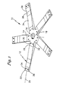
- Fig. 1 is a perspective showing of our five-legged flexbeam.
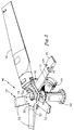
- Fig. 2 is a partial showing, partially broken away, illustrating our five-legged flexbeam in its helicopter rotor environment.
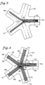
- Fig. 3 is a showing of the initial lay-up steps of the composite material which will form our five-legged flexbeam.
- Fig. 4 is similar to Fig. 3 but shows the composite material lay-up at a later stage in the lay-up process, but confined to the lay-up of full length plies of composite material comprising unidirectionally extending high tensile strength fibers with filler plies of similar construction filling in the interstices therebetween.
- Fig. 5 is an illustration of the lay-up of the taper cross plies used in the fabrication of our five-legged flexbeam.
- Fig. 6 is an illustration of the method of lay-up of the taper plies having unidirectionally high tensile strength fibers therein.
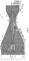
- Fig. 7 is a cross-sectional showing through one of the legs of our flexbeam to show the lay-up of the plies in our preferred embodiment.
- Fig. 1 shows such a multi-legged flexbeam 10 of one-piece construction and consisting of a plurality of preferably five legs, such as 12, which are equally spaced circumferentially about the axis 14 of the flexbeam central aperture 16, and which will be coincident with the rotor axis of rotation.
- the flexbeam includes a hub portion 18 which is concentric about axis 14 and has legs 12 extending radially outwardly therefrom.
- Each leg 12 has a substantially radial axis or centerline 20, about which it is symmetrical, and the radial axes of all legs 12 lie in a common plane perpendicular to axis 14 or in a common shallow angle cone with axis 14.
- Each leg 12 is fabricated such that it has a region 22 of substantial cross-sectional area and hence structural integrity at the radially outer end thereof.
- Bolt holes 24 and 26 extend through region 22 and receive connecting bolts which serve to connect the flexbeam 10 to the helicopter rotor blade.
- hub 18 and the inboard ends 28 of legs 12 are of substantial cross-sectional area.
- Bolt holes 30 and 32 extend through the inboard end 28 of each leg 12 to form a ring of bolt holes.
- each leg 12 includes section 34 which tapers in a radially outward direction from blade inboard end 28 and also includes section 36 which tapers radially inwardly from blade outboard end 26. Tapered sections 34 and 36 terminate on opposite sides of minimal cross-sectional station 38 of leg 12. This minimal cross-sectional area 38 permits flexbeam 10 to move in pitch change, lead-lag and flapping motion with the helicopter blade which it supports.
- Each leg is of simple rectangular cross-sectional shape at each station throughout its length, and with the larger dimension of the rectangle extending in the plane of blade radial axes 20.
- This rectangular cross-sectional shape provides the advantage of ease of manufacture.
- the legs 12 may be rotated about their radial axis 20 to create a pretwist configuration.
- FIG. 2 shows the multi-legged flexbeam 10 in a portion of its helicopter rotor environment.
- Bearingless flexbeam helicopter rotor 40 includes the five-legged flexbeam 10, whose legs 12 extend radially outwardly from axis of rotation and central aperture axis 14. The outer end of each leg 12 is connected in a conventional fashion to a helicopter blade 25 by connecting bolts which extend through apertures 24 and 26. In conventional fashion (not shown), blade 25 is connected to torque tube 42.
- Torque tube 42 is connected to swashplate 44 through pitch control rods 46, such that each blade 25 can be caused to change pitch in response to the motion of swashplate 44 acting through pitch control rod 46 and torque tube 42.
- Upper clamp plate 48 is positioned on the top surface of flexbeam 10, while lower hub plate 50 is positioned on the lower surface of flexbeam 10.
- Each of these clamp plates includes a plurality of bolt holes 52, through which a circumferential array of connecting bolts extends to connect the two plates 48 and 50 to flexbeam 10, and hence connect flexbeam 10 to the rotor drive shaft (not shown), but which is enveloped by mast 54, and which causes the rotor 40 to rotate about axis 14.
- flexbeam 10 must be capable of accommodating pitch change, lead-lag and flapping motions of the blades 42. It will further be noted that with this construction, if a single connecting bolt 30 or 32 passing through flexbeam leg 12 inner ends is ruptured, the coaction of the two clamp plates 48 and 50, and the other bolts will serve to continue to position the blade which is connected to the particular flexbeam leg which held the failed bolt.
- our full length plies define an aperture in the center of the hub, which may not have to be enlarged and, therefore, need not be weakened by the severing of fibers in any type of a hole drilling operation.
- a tool member 60 whose inner periphery defines the precise shape desired for the multi-legged flexbeam 10 is provided.
- ply 62 which consists of a plurality of unidirectionally extending high tensile strength fibers, such as fiberglass, graphite or KEVLAR® (Trademark of E.I. DuPont), extends from the radially outer end of tool leg 64 radially inwardly and in close proximity to what will become hub portion 18 and then extends radially outwardly for the full length of a second tool leg 66.
- leg 66 is in substantial radial alignment with and diametrically opposed to leg 64, and that ply 62 occupies one-half of the width of legs 64 and 66. Since a ply such as 62 will be extending the full length of the flexbeam, they will be referred to as a full length ply.
- a second full length ply consisting of unidirectional high tensile strength fibers is laid-up in leg 64 so as to occupy the other half of the width thereof and extend radially therealong and through what will become hub portion 18 and then radially outwardly into a second leg 70 which is also substantially diametrically opposed to leg 64.
- plies 62 and 68 cooperate to provide a full width ply for leg 64, and split or bifurcate at the end of leg 64 in passing through hub section 18, and ply 62 occupies one half the width of one substantially diametrically opposed leg 66, while ply 68 occupies one half the width of a second substantially diametrically opposed leg 70.
- filler ply 73 and the other filler plies to be described hereinafter, is to form a smooth surface with the adjacent plies 62 and 68 so that the next ply to be laid-up thereover will have a smooth surface to lay against, and will not be indented or kinked in the interstices filled by filler ply 73, which could be the case without filler ply 73 being present. Such kinks would create stress concentrations in the fiber ply during rotor operation.
- Full length ply 72 is then laid up in leg 74 to occupy one half of the width thereof, and extend radially inwardly therein through hub portion 18 into one substantially diametrically opposed leg 76, then filler plies 78 and 80 are laid up, followed by full length ply 82, which occupies the other half of the width of leg 74, and cooperates with ply 72 to extend the full width of leg 74 and extends radially inwardly therefrom in close proximity through hub portion 18 and then radially outwardly in leg 66 to occupy one half of the width thereof, and cooperate with ply 62 to occupy the full width of leg 66.
- full length ply 88 is laid up commencing at the radially outer end of leg 70 to occupy one half the width thereof and cooperate with full length ply 68 to occupy the full width thereof, and extending radially inwardly within leg 70 to pass through hub portion 18 and radially outwardly into leg 76 to cooperate with ply 72 to fill the full width of leg 76.
- a first taper ply 92 is laid up on the initial full length lay-up described in connection with Figs. 3 and 4. It will be noted that ply 92 is shaped to fill the full width of slot 64 and to abut full length ply 72 at its inner end and extend radially outwardly therefrom to terminate at a selected station along the length of arm 64. At the same time, a second taper ply 94 will be laid up commencing at the radially outer end of leg 64 and in alignment with the outer end of plies 62 and 68 and extend radially inwardly while extending across the full width of leg 64 and terminating at a selected station therealong short of taper ply 92.
- taper plies 96 and 98 may be laid up in leg 76
- taper plies 100 and 102 may be similarly laid up in leg 66
- taper plies 104 and 106 may be laid up in leg 70
- taper plies 108 and 110 may be laid up in leg 74.
- Taper plies 92 through 110 are preferably cross ply having fibers extending at an angle of about 45° with respect to the unidirectional fibers in unidirectional plies 62 through 88.
- a second layer of unidirectional full length plies may be laid up, as previously described in connection with Figs. 3 and 4, followed by a second layer of filler plies corresponding to filler plies 92 through 110 described in connection with Fig. 5 but preferably being cross ply with the unidirectional fibers thereof forming an angle of -45° with the unidirectional plies 62 through 88.
- Each of the taper plies comprise a plurality of unidirectional high tensile strength fibers oriented to extend in the direction of the leg which they occupy.
- plies 62′ and 68′ occupy the full width of leg 64 and extend therefrom in bifurcated fashion into substantially diametrically opposite legs 66 and 70.
- Plies 72′ and 82′ similarly occupy the full width of leg 74 and extend therefrom through the hub portion 18 in close proximity to axis 14 into substantially diametrical legs 66 and 76.
- plies 88′ and 68′ occupy the full width of leg 70 and extend radially inwardly therein in close proximity to axis 14 and into substantially diametrically opposed legs 64 and 76.
- Filler plies such as 73′, 78′, 84′, 86′ and 80′, as previously described in connection with Figs. 3 and 4, are laid up in connection with the Fig. 6 lay-up to fill the interstices between the unidirectional taper plies in the same fashion as with the Figs. 3 and 4 lay-up.
- the lay-up just described in connection with the Fig. 6 taper plies is identical with the lay-up previously described in connection with the full length plies described in connection with Figs. 3 and 4, except that the plies are of shorter length and cooperate with the taper plies 92, 96, 100, 104 and 108 shown in Fig. 5 to define the taper portion 34 of the flexbeam legs 12.
- Fig. 7 will be described as it relates to the lay-up of flexbeam leg 12 occurring in leg 64 of the tool 60, however, it should be borne in mind that similar lay-ups are occurring at the same time in all other legs of the flexbeam.
- the bottom layer is formed by full length plies 62 and 68 as described in connection with Figs. 3 and 4.
- Plies, such as 91 and 93, are unidirectional full length or unidirectional taper plies from other legs 12 of flexbeam 10.
- the next layer working from the bottom is formed by taper plies 92 and 94.
- 3 and 4 is also a full length ply and will be identified as 62a, 68a.
- the next lay-up will be taper plies corresponding to 92 and 94 of Fig. 5, but shorter in length and identified as 92a and 94a.
- the next ply to be laid-up is a full length ply identified as 62b, 68b.
- the next ply to be laid-up as described in connection with Fig. 5 is taper plies identified as 92b and 94b. This will be followed by a full length ply 62c, 68c.
- alternate taper plies will be cross plies of +45° and -45° fibers with respect to the unidirectional fibers of full length plies and the unidirectional taper plies which are to be laid-up next.
- taper ply 92c unidirectional taper ply 62′ and 68′, then taper ply 92d, are laid. up upon full length ply 62c, 68c, at the same time that taper ply 94c is laid up at the outboard end of leg 12.
- Unidirectional taper ply 62′, 68′ will be laid up as described in connection with Fig. 6, while taper plies 92e and 92f will be laid up as described in connection with Fig. 5.
- Unidirectional full length ply 62d, 68d will then be laid up.
- the lay-ups consist of alternate layers of +45° taper plies such as 94d, and -45° taper plies such as 94e, laid up on opposite sides of full length unidirectional fiber plies such as 62e, 68e. This pattern of lay-up will be continued until the lay-up reaches the centerline 20 of leg 12, ending with full length unidirectional ply 62f, 68f, taper ply 92g, and taper ply 94f.
- the taper plies are cut or terminated so that the inboard plies are successively shorter than the outboard plies below axis 20 so that there are no substantial voids between ply intersections, for example, at ply intersections 96 and 98. This is important because if there were substantial voids, such as 96 and 98, this would establish resin pockets in the flexbeam legs 12, and these would be areas of minimal strength.
- the various plies are preferably made of fiberglass, graphite or KEVLAR and are preferably all about .020 inches thick.
- the plies of flexbeam 10 may be preimpregnated with resin prior to lay-up or may be laid-up dry and then have resin, such as epoxy, injected thereinto when the laid-up flexbeam is positioned within mating fixtures which cooperate to define the shape of the flexbeam 10 so that each leg is of the shape shown in Fig. 7.
- resin such as epoxy
- Our preferred matrix is a thermoset using an epoxy. If we were to use a thermoplastic matrix, we would probably use PEEK (Polyetheretherkeytone) sold by ICI Composites, Inc. of Wilmington, Delaware, and other companies.
- each leg 12 of flexbeam 10 consists basically of unidirectional full length plies extending for the full length of each leg 12 and laid-up as described in connection with Figs. 3 and 4, and with selected +45°, -45°, and unidirectional taper plies disbursed selectively therebetween, as described in connection with Figs. 5 and 6, respectively, to cause the multi-legged flexbeam 10 to achieve the desired shape.
- the lay-up pattern is such that, except for the outer layers, every fourth ply laid up is a unidirectional full length ply, and at the outboard end of the leg, every second ply laid up is a unidirectional full length ply.
- This substantial use of the full length plies avoids having large numbers of taper plies cut off somewhere along the length of the flexbeam arm, thereby creating stress concentration at that point.
- the flexbeam composite material is cured.
- the preferred curing process is a combination of temperature and pressure as specified by the resin manufacturer.
- the centrifugal loads imparted by the blade are reacted by the full length unidirectional fibers of the flexbeam leg 12 that supports that blade, and are carried to two substantially diametrically opposed arms on the opposite side of the flexbeam.
- the centrifugal force is imparted to the opposite arms of the flexbeam, rather than all having to be reacted by the connecting bolts which pass through apertures 30 and 32.
- the unidirectional fibers of the full length plies are capable of withstanding substantial blade centrifugal loading, and has the additional advantage of having a benign failure mode which is readily detected visually in that delamination occurs due to the initial breakdown of the composite.
Landscapes
- Engineering & Computer Science (AREA)
- Mechanical Engineering (AREA)
- Chemical & Material Sciences (AREA)
- Composite Materials (AREA)
- Aviation & Aerospace Engineering (AREA)
- Moulding By Coating Moulds (AREA)
Applications Claiming Priority (2)
| Application Number | Priority Date | Filing Date | Title |
|---|---|---|---|
| US64123791A | 1991-01-15 | 1991-01-15 | |
| US641237 | 1991-01-15 |
Publications (2)
| Publication Number | Publication Date |
|---|---|
| EP0496695A2 true EP0496695A2 (fr) | 1992-07-29 |
| EP0496695A3 EP0496695A3 (en) | 1993-04-21 |
Family
ID=24571540
Family Applications (1)
| Application Number | Title | Priority Date | Filing Date |
|---|---|---|---|
| EP19920630005 Withdrawn EP0496695A3 (en) | 1991-01-15 | 1992-01-09 | A unitary, multi-legged helicopter rotor flexbeam made solely of composite materials and the method of manufacturing same |
Country Status (1)
| Country | Link |
|---|---|
| EP (1) | EP0496695A3 (fr) |
Cited By (11)
| Publication number | Priority date | Publication date | Assignee | Title |
|---|---|---|---|---|
| WO1994027866A1 (fr) * | 1993-06-02 | 1994-12-08 | United Technologies Corporation | Poutre de flexion pour ensemble a rotor principal sans paliers d'helicoptere |
| DE19701403C1 (de) * | 1997-01-17 | 1998-02-26 | Eurocopter Deutschland | Mehrblattrotor für ein Drehflügelflugzeug |
| GB2356642A (en) * | 1999-11-25 | 2001-05-30 | Dunlop Aerospace Ltd | Wear resistant articles |
| WO2005051624A3 (fr) * | 2003-11-27 | 2008-02-14 | Conchur O'bradaigh | Element de raccordement d'un equipement |
| EP1899146B1 (fr) * | 2005-05-03 | 2012-04-04 | The Boeing Company | Procede de fabrication d'elements structurels composites incurves |
| US8932423B2 (en) | 2008-04-17 | 2015-01-13 | The Boeing Company | Method for producing contoured composite structures and structures produced thereby |
| US9090028B2 (en) | 2008-04-17 | 2015-07-28 | The Boeing Company | Method for producing contoured composite structures and structures produced thereby |
| US9096305B2 (en) | 2008-04-17 | 2015-08-04 | The Boeing Company | Curved composite frames and method of making the same |
| EP2778053B1 (fr) * | 2013-03-13 | 2016-02-03 | Bell Helicopter Textron Inc. | Orientation des fibres afin de permettre un placement de couche automatisée avec jougs à rotor composite |
| US9278484B2 (en) | 2008-04-17 | 2016-03-08 | The Boeing Company | Method and apparatus for producing contoured composite structures and structures produced thereby |
| US20210387437A1 (en) * | 2020-06-12 | 2021-12-16 | Airbus Operations S.L. | Composite structure and manufacturing method |
Family Cites Families (2)
| Publication number | Priority date | Publication date | Assignee | Title |
|---|---|---|---|---|
| US3765267A (en) * | 1969-05-20 | 1973-10-16 | Aerospatiale | Connecting element between two members enabling them to rotate in relation to one another in three axes |
| US4746272A (en) * | 1986-07-23 | 1988-05-24 | United Technologies Corporation | Lobed composite flexbeam |
-
1992
- 1992-01-09 EP EP19920630005 patent/EP0496695A3/en not_active Withdrawn
Cited By (18)
| Publication number | Priority date | Publication date | Assignee | Title |
|---|---|---|---|---|
| WO1994027866A1 (fr) * | 1993-06-02 | 1994-12-08 | United Technologies Corporation | Poutre de flexion pour ensemble a rotor principal sans paliers d'helicoptere |
| AU679105B2 (en) * | 1993-06-02 | 1997-06-19 | United Technologies Corporation | A flexbeam for a helicopter bearingless main rotor assembly |
| KR100311561B1 (ko) * | 1993-06-02 | 2002-10-18 | 유나이티드 테크놀로지즈 코포레이션 | 헬리콥터무베어링주회전익조립체용의플렉스비임 |
| DE19701403C1 (de) * | 1997-01-17 | 1998-02-26 | Eurocopter Deutschland | Mehrblattrotor für ein Drehflügelflugzeug |
| GB2356642A (en) * | 1999-11-25 | 2001-05-30 | Dunlop Aerospace Ltd | Wear resistant articles |
| GB2356642B (en) * | 1999-11-25 | 2001-12-05 | Dunlop Aerospace Ltd | Wear resistant articles |
| US6660355B2 (en) | 1999-11-25 | 2003-12-09 | Dunlop Aerospace Limited | Wear resistant articles |
| WO2005051624A3 (fr) * | 2003-11-27 | 2008-02-14 | Conchur O'bradaigh | Element de raccordement d'un equipement |
| EP1899146B1 (fr) * | 2005-05-03 | 2012-04-04 | The Boeing Company | Procede de fabrication d'elements structurels composites incurves |
| US8632653B2 (en) | 2005-05-03 | 2014-01-21 | The Boeing Company | Method of manufacturing curved composite structural elements |
| US9630390B2 (en) | 2005-05-03 | 2017-04-25 | The Boeing Company | Method of manufacturing curved composite structural elements |
| US8932423B2 (en) | 2008-04-17 | 2015-01-13 | The Boeing Company | Method for producing contoured composite structures and structures produced thereby |
| US9090028B2 (en) | 2008-04-17 | 2015-07-28 | The Boeing Company | Method for producing contoured composite structures and structures produced thereby |
| US9096305B2 (en) | 2008-04-17 | 2015-08-04 | The Boeing Company | Curved composite frames and method of making the same |
| US9278484B2 (en) | 2008-04-17 | 2016-03-08 | The Boeing Company | Method and apparatus for producing contoured composite structures and structures produced thereby |
| EP2778053B1 (fr) * | 2013-03-13 | 2016-02-03 | Bell Helicopter Textron Inc. | Orientation des fibres afin de permettre un placement de couche automatisée avec jougs à rotor composite |
| US20210387437A1 (en) * | 2020-06-12 | 2021-12-16 | Airbus Operations S.L. | Composite structure and manufacturing method |
| US11707907B2 (en) * | 2020-06-12 | 2023-07-25 | Airbus Operations S.L. | Composite structure and manufacturing method |
Also Published As
| Publication number | Publication date |
|---|---|
| EP0496695A3 (en) | 1993-04-21 |
Similar Documents
| Publication | Publication Date | Title |
|---|---|---|
| CA1102774A (fr) | Chape composite lamellee pour rotor | |
| US20240060582A1 (en) | Composite connectors and methods of manufacturing the same | |
| JP4504374B2 (ja) | ロータブレードの編組翼桁とその製造方法 | |
| EP0888235B1 (fr) | Structure composite de manchon de pied de pale pour rotors d'helicoptere | |
| US10280969B2 (en) | Hybrid metal-composite drive shaft unit and method of manufacturing same | |
| RU2126343C1 (ru) | Лонжерон упругий для бесподшипникового узла несущего винта вертолета | |
| AU639197B2 (en) | An articulated helicopter rotor with an improved blade-to- hub connection | |
| US4650401A (en) | Flat strap cruciform flexure for helicopter rotor systems | |
| US5810562A (en) | Composite rotating swashplate for a helicopter rotor system | |
| EP0448705B1 (fr) | Pale de rotor | |
| EP2634091B1 (fr) | Joug composite de retenue de pales d'hélicoptère | |
| IL102867A (en) | Bearingless main motor assembly torque tube and method for fabricating same | |
| US4797064A (en) | Composite helicopter rotor hub | |
| US6974555B2 (en) | Method of fabricating a damage tolerant shaft | |
| US11635110B2 (en) | Composite flexible coupling | |
| US5462409A (en) | Leading edge weight retention assembly for a helicopter rotor | |
| US6375426B1 (en) | Protective edge members for composite flexures | |
| US5158631A (en) | Method of manufacturing a dog-leg shaped ply of composite material and the tool used in carrying out the method | |
| KR102040595B1 (ko) | 항공기 로터 블레이드 및 그의 성형 방법 | |
| US4818179A (en) | Composite helicopter rotor hub | |
| US11473663B1 (en) | Continuous fiber composite power transfer structures | |
| JPH045505B2 (fr) |
Legal Events
| Date | Code | Title | Description |
|---|---|---|---|
| PUAI | Public reference made under article 153(3) epc to a published international application that has entered the european phase |
Free format text: ORIGINAL CODE: 0009012 |
|
| AK | Designated contracting states |
Kind code of ref document: A2 Designated state(s): DE FR |
|
| PUAL | Search report despatched |
Free format text: ORIGINAL CODE: 0009013 |
|
| AK | Designated contracting states |
Kind code of ref document: A3 Designated state(s): DE FR |
|
| 18D | Application deemed to be withdrawn |
Effective date: 19931022 |