EP0497191B1 - Dispositif d'actionnement d'un appareil de cuisson et procédé de commande - Google Patents
Dispositif d'actionnement d'un appareil de cuisson et procédé de commande Download PDFInfo
- Publication number
- EP0497191B1 EP0497191B1 EP92100952A EP92100952A EP0497191B1 EP 0497191 B1 EP0497191 B1 EP 0497191B1 EP 92100952 A EP92100952 A EP 92100952A EP 92100952 A EP92100952 A EP 92100952A EP 0497191 B1 EP0497191 B1 EP 0497191B1
- Authority
- EP
- European Patent Office
- Prior art keywords
- control
- adjusting member
- sensor arrangement
- control according
- cooking device
- Prior art date
- Legal status (The legal status is an assumption and is not a legal conclusion. Google has not performed a legal analysis and makes no representation as to the accuracy of the status listed.)
- Expired - Lifetime
Links
Images

Classifications
-
- H—ELECTRICITY
- H05—ELECTRIC TECHNIQUES NOT OTHERWISE PROVIDED FOR
- H05B—ELECTRIC HEATING; ELECTRIC LIGHT SOURCES NOT OTHERWISE PROVIDED FOR; CIRCUIT ARRANGEMENTS FOR ELECTRIC LIGHT SOURCES, IN GENERAL
- H05B3/00—Ohmic-resistance heating
- H05B3/68—Heating arrangements specially adapted for cooking plates or analogous hot-plates
- H05B3/74—Non-metallic plates, e.g. vitroceramic, ceramic or glassceramic hobs, also including power or control circuits
-
- F—MECHANICAL ENGINEERING; LIGHTING; HEATING; WEAPONS; BLASTING
- F24—HEATING; RANGES; VENTILATING
- F24C—DOMESTIC STOVES OR RANGES ; DETAILS OF DOMESTIC STOVES OR RANGES, OF GENERAL APPLICATION
- F24C15/00—Details
- F24C15/10—Tops, e.g. hot plates; Rings
- F24C15/102—Tops, e.g. hot plates; Rings electrically heated
- F24C15/106—Tops, e.g. hot plates; Rings electrically heated electric circuits
-
- F—MECHANICAL ENGINEERING; LIGHTING; HEATING; WEAPONS; BLASTING
- F24—HEATING; RANGES; VENTILATING
- F24C—DOMESTIC STOVES OR RANGES ; DETAILS OF DOMESTIC STOVES OR RANGES, OF GENERAL APPLICATION
- F24C7/00—Stoves or ranges heated by electric energy
- F24C7/08—Arrangement or mounting of control or safety devices
- F24C7/082—Arrangement or mounting of control or safety devices on ranges, e.g. control panels, illumination
- F24C7/083—Arrangement or mounting of control or safety devices on ranges, e.g. control panels, illumination on tops, hot plates
-
- H—ELECTRICITY
- H01—ELECTRIC ELEMENTS
- H01H—ELECTRIC SWITCHES; RELAYS; SELECTORS; EMERGENCY PROTECTIVE DEVICES
- H01H36/00—Switches actuated by change of magnetic field or of electric field, e.g. by change of relative position of magnet and switch, by shielding
- H01H36/0006—Permanent magnet actuating reed switches
- H01H36/006—Permanent magnet actuating reed switches comprising a plurality of reed switches, e.g. selectors or joystick-operated
Definitions
- the present invention relates to a method for controlling the operation of a cooking device according to the preamble of claim 1 and a cooking device control with at least one actuator for controlling the cooking device according to the preamble of claim 8.
- the present invention relates in particular to the construction of cooktops with a glass ceramic plate, it can be advantageous in general for cooking appliances, i.e. e.g. can also be used for ovens or cookers.
- the cooking appliance is always activated when the actuator is in any of the intended tax effective positions is set. It should be borne in mind that the advantage of extremely simple operation with the actuator also includes the risk of such operation, and consequently activation of the cooking appliance, by unauthorized persons, in particular children, or due to carelessness.
- a magnetic field-sensitive sensor is triggered in each control-effective slide position and emits a control-effective signal.
- This procedure is disadvantageous in two different respects, firstly in the safety aspect, because magnetic field-sensitive sensors, such as reed switches, can very well be triggered by other, randomly magnetized objects, such as pan bases, etc. If such a sensor is triggered in the known procedure, the cooking device is activated. Furthermore, the above-mentioned procedure is under the aspect of constructive effort given a number of states to be controlled, such as heating power levels, disadvantageous. This is because a sensor is provided for each intended tax effective position and triggers a predetermined control state.
- one control-effective signal can be controlled by a combined triggering of several sensors, which significantly increases the number of possible switching states for a given number of magnetic field-sensitive sensors.
- the procedure according to the invention significantly improves the practical usability of the known method from the point of view of the user.
- the magnetic circuit is put through the glass ceramic plate, which does not require any mechanical impairment or processing of the glass plate.
- the problem of cleaning is solved in the procedure according to the invention in that the plate, and, in particular in the case of a glass ceramic hob, the glass ceramic plate, can be cleaned without problems after removal of the actuator or actuators. This is preferably facilitated by the fact that the movement guide is provided at the edge of the plate and / or can be removed, such as plugged on.
- the actuator or actuators are preferably arranged at the top, since they do not adversely affect the available work surface.
- An actuator can be moved very quickly, so that the adjustability is very direct.
- Providing displays be it on the plate or an intended guide, if necessary providing illuminated displays, such as illuminated bar displays or acoustic displays, ensures that the position of the actuator can be easily recognized, even from a distance.
- illuminated displays such as illuminated bar displays or acoustic displays
- a significant reduction in the interference problem is achieved. If, for example and preferably, reed relays are provided as magnetically controllable switches, it can be seen that the mains switching problem is eliminated. This provides the often prescribed electromechanical switch.
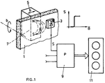
- a magnetic field sensor 3 is arranged on one side of this plate 1, which can be, for example, a Hall sensor, but preferably, and as will be described in detail, a reed switch.
- An actuator slide 5 with a permanent magnet arrangement 7, which detects the magnetic field, is provided as the actual actuator on the side of the plate 1 facing away from the magnetic field sensor 3 B ⁇ , through the plate 1, generated.
- the magnetic field-sensitive sensor 3 basically has a magnetic field / electrical signal transmission characteristic, as is shown in FIG. 1, its electrically acting output, together with corresponding outputs from usually further, provided magnetic field sensors 3, to a power control unit 9, for example working on the basis of the pulse packet control, managed as described in W087 / 04815. This provides the performance of the cooking device, such as the hob 11, depending on whether and which of the magnetic field sensors 3, by appropriate movement and positioning of the actuator slide 5 or its magnetic field B ⁇ have been activated.
- the movement path for the slide 5, along a plurality of magnetic field sensors 3 provided can be linear or curved or even circular, as shown by the arrows b. It is performed according to the invention.
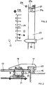
- FIG. 2 is schematically, in cross section, a preferred Embodiment variant of a control according to the invention operating according to this method is shown.
- a guide rail 15 is mounted on the edge of a glass ceramic plate 13 of a cooktop (not shown further), possibly also removable, along which one or more actuator slides 17, pointer-shaped, can be displaced.
- the edge of the cooking device itself or a strip which is provided on the cooking device anyway, or another molding or shaping which is provided on the cooking device anyway, can also serve as a guide, with the slides being designed accordingly.
- One or more schematically illustrated permanent magnets 19 are integrated in the actuator slides 17, each around a predetermined magnetic field pattern B ⁇ to create.
- the magnet arrangements 19 in the various slides provided can be designed differently in order to selectively trigger different or differently arranged magnetic field-sensitive sensors.
- the magnetic field-sensitive sensors shown generally and schematically with 3 in FIG. 1 are realized in a very simple and preferred embodiment variant by reed switches 21. They are arranged below the glass ceramic plate 13 in such a way that when the or a specific actuator slide 17 is set in a predetermined position along the guide 15, the switch 21 is attracted and, as has been explained schematically with reference to FIG. 1, an electrical actuating signal on the Power control 9 switches.
- the actuator slide 17 can be removed by a simple handle, be it by pushing it out of the guide 15 or by tipping it out, with a correspondingly elastic guide rail 23 for the slide 17, so that the slide 17 can be supplied when the cooking appliance is not in use, thus providing optimal child safety is reached.
- the entire glass ceramic surface can also be used for other purposes and can be easily cleaned.
- the slider 17 and the guide rail 23 can be easily tensioned with respect to one another by means of leaf springs inserted into the guide, in order to provide a smooth guide.
- FIG. 3 schematically shows a top view of such an arrangement with a slide 17.
- an end stop surface 27 is preferably provided for the respective slide 17, optionally, as shown at 27 a, resiliently, with which a defined stop is realized along the movement path of the slide 17 formed by rail 23.
- At the end stop 27 there is also preferably a one / two-circuit switch 27b is provided for the hotplate assigned to the slide in question.
- the first actuation by means of the slide 17 switches the plate from one to two-circuit operation, the second back to single-circuit operation.
- This operating mode is preferably e.g. indicated by an LED 27c.
- the spring-loaded positioning on the stop surface 27 is preferably also used for switching on the current to the cooking appliance.
- the slide 17 in turn activates a sensor sensitive to a magnetic field, such as preferably a reed relay.
- a sensor sensitive to a magnetic field such as preferably a reed relay.
- This has the essential advantage that the cooking appliance can only be energized if a slide 17 is placed in this predetermined position.
- switching on / off can be combined with the one / two-circuit switchover mentioned, for example by a reed relay switching on cyclically via a counter, switching to single-circuit operation, the next switching operation, switching to dual-circuit operation, the third in the off mode.
- Position displays by means of bar-illuminated displays and / or acoustically are also possible.
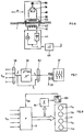
- a four-burner hob with the four provided actuator slides 17 is shown schematically in supervision.
- two correspondingly aligned magnetic field sensitive sensors 3a and 3b are arranged, for example.
- the electrical active outputs of these sensors are combined with one another via respective AND links 31. Only when the two logically linked sensors are activated together in one position of the slide or magnet 19 does a signal become effective on the output side of the AND link 31.
- the sensor arrangement and the permanent magnet arrangement are therefore designed, if necessary with the aid of guide plates for the magnetic field, in such a way that control-effective sensor activation can only take place if the magnetic field specifically corresponds to that of the permanent arrangement 19 and at a very specific position along the path 23a shown in dashed lines occurs for the slider.
- the sensors 3 can in principle be any magnetic field-sensitive sensors according to FIG. 1, at least one pair of sensors 33 is preferably designed as a pair of reed switches connected in series with an AND operation. This pair of sensors 33 controls an electromechanical unit 37 with which the network 36 is switched on or off.
- the unit 37 is a relay or contactor unit. As a result, the required electromechanical connection of the cooking appliance power is continuously implemented.
- the network can be switched on and off via the latter.
- the Mains connection occurs when any two of the AND-combined reed switches are activated, for which purpose the pairs of these AND-linked reed switches are connected to unit 37 via OR wiring (in parallel).
- the arrangement of the pair of reed switches 33 means that the cooking appliance can only be switched to active if the slide corresponding to the permanent magnet 19 is moved into the position corresponding to the pair of reed switches 33 before it is moved to any of the other positions. Since this is certainly not the case with a magnetic object that is accidentally placed on the disk, the immunity to interference is significantly increased as a result.
- the pair of reed switches 33 is preferably provided directly at an initial stop 39 in such a way that it is easy for an operator to set the slide in the required switch-on position corresponding to the ON position in FIG. 3.
- the result is that with the Pair 33, given priority, a further mode of operation, namely that the cooking appliance is only put into operation if the switch pair 33 has been activated for the time being and then another of the AND-linked reed switch pairs. While the unit 37 is switched on with the switch pair 33 due to the often required electromechanical actuation, what can then be done electronically is first switched to the hob plate assigned to the respective slide by means of the further reed switch pairs.
- a light indicator 41 can be provided, which indicates that the cooking appliance is switched on as a function of the connection of the pair of reed switches 33 shown in FIG. 5.
- a specific power level for the cooking device in each given slide position for example via a pulse packet control
- several sensors 3 are activated in a specific slide position, for example the pair I and II in one position and the pair II in a further position alone, in a further position, the pair II and III, etc., and that the outputs of the AND gates 31 are routed to a logical combination unit 43, by means of which, based on the respective combination of activated sensor pairs, output control signals S p spent on the hob.
- baffles or pole shoes are provided in order to generate a control-effective signal when inserting the slide 17 only in a precisely defined position, as via the reed relay 21 shown there, preferably used, the hysteresis behavior of such a magnetic circuit may have to be taken into account. This is because, due to the hysteresis behavior mentioned, when the slide 17 is positioned sequentially in the same way, this does not need to control the underlying sensor immediately.
- FIG. 6 schematically shows a further embodiment variant of the procedure according to the invention.
- a coil 40 is provided with a U-core 42, the legs of which face the surface of the plate 1.
- the coil 40 is, for example, part of the frequency-determining resonant circuit of an oscillator 44, the change in its impedance ⁇ Z. ⁇ , as shown schematically at 46, is recorded to form the signal S according to FIG. 1.
- a slide 48 in turn comprises a coil 50 with a U-core 52, the legs of which face those of the core 42. Coils 40 and 50 are thus formed as well like the cores 42 and 52 a transformer.
- the transformer, electromagnetically transmitted energy in the slider 48 is utilized by a correspondingly designed converter unit 54, for example an AC / DC converter, a display, such as an LED display 56, to feed in the slider 48 itself.
- a display such as an LED display 56
- the display 56 is activated when the slider 48 or the secondary side of the transformer converter with the primary side, i.e. Oscillator unit 44, with coil 40 and core 42, is closely coupled.
- FIG. 7 shows a power control that is preferably used in connection with the present invention on the basis of a functional block diagram.
- the output signals of each AND-linked sensor 3 according to FIG. 5, ie the signals S 31, are OR-linked at 58, a time-setting unit 60 which essentially acts as a mono-stable, resettable multivibrator.
- the output of unit 60 is ORed at 62 with the output signal of the OR link 58 to the electromechanical power switching unit 37 according to FIG. 5 and controls it.
- the power on the corresponding hob or on the corresponding hotplate is primarily controlled with the signals S 31, as was explained with reference to FIG. 5.
- the power is applied to the unit 37 electromechanically, for example via the reed switches 33 from FIG. 5.
- the unit 60 is set and drops after the predetermined time period ⁇ , with which The network switching unit 37 is then switched off via the OR link 62. This also takes place when none of the signals S 31 is active, i.e. all slides with magnet 19 according to FIG. 5 are removed, for example.
- the cooking appliance operation is switched off at the latest after the predeterminable time ⁇ , which can be, for example, half an hour, provided that the signals S 31 have not been changed by adjusting the slide, and consequently a signal edge which is effective for the time setting unit 60 resumed.
- the predeterminable time ⁇ which can be, for example, half an hour
- This procedure as a backup, therefore switches the cooking appliance off after the predetermined time period ⁇ , which corresponds to a time during which experience has shown that a cooking appliance is at most left in unchanged operation.
- FIG. 8 schematically shows a further power control that is preferably used in connection with the present invention.
- the signals S 31 basically control the power control unit 9 for the existing hot plates of a field 11.
- the total power which is given to the hob 11 is determined on a unit 64 which is shown schematically as a summation unit. If this total power exceeds a predetermined value Q, a control signal S 66 is generated at a gradation unit 66, which, fed back to the power control unit 9, reduces the power to the respective fields 11a to 11d, automatically, preferably in proportion to that then the signals S 31 controlled, 11 x power supplied to the respective field.
- the procedure according to the invention described is particularly suitable for actuators which can be operated from above.
- the actuators or sliders provided according to the invention can be moved quickly, and in particular provision of displays at the corresponding slider positions or activation of the corresponding sensors results in good readability.
- the slides can be made relatively large and towering, so that it can be seen from a distance in which position each slider is located.
- the actuators 17 or 48 can be removed makes it extremely easy to clean the plate, in particular the glass-ceramic plate of the field, and the use of a magnetic circuit coupling already results in a considerably higher level of interference resistance than in the case of known capacitive sensors.
- the preferred embodiment variant with reed switches is particularly immune to interference, which is further improved by the aforementioned combined connection of several sensors or reed switches.
- the removability of the slider results in optimal child safety. Only a small operating force is required to operate the slide, and in spite of the actuator arrangement located above, no penetrations through the glass ceramic plate or generally the plate made of magnetically permeable material are necessary.
Landscapes
- Engineering & Computer Science (AREA)
- Chemical & Material Sciences (AREA)
- Combustion & Propulsion (AREA)
- Mechanical Engineering (AREA)
- General Engineering & Computer Science (AREA)
- Ceramic Engineering (AREA)
- Electric Stoves And Ranges (AREA)
Claims (21)
- Procédé d'actionnement d'un appareil de cuisson, dans lequel au moins un circuit magnétique traversant une base à perméabilité magnétique est modifié, au moyen d'un organe de réglage mobile, sur un côté de la base et cette modification est enregistrée sur l'autre côté de la base de manière à agir sur la commande, caractérisé en ce que la trajectoire de déplacement de l'organe de réglage est guidée mécaniquement (23) et des positions prédéterminées de l'organe de réglage sont prédéterminées mécaniquement.
- Procédé selon la revendication 1, caractérisé en ce que l'organe de réglage (5, 17) doit d'abord être placé dans une position (27) prédéterminée avant de pouvoir agir sur la commande du chauffage de l'appareil de cuisson par déplacement dans d'autres positions.
- Procédé selon l'une des revendications 1 ou 2, caractérisé en ce fait que des capteurs de champ magnétique sont prévus à des emplacements discrets sur l'autre côté de la base et les sorties d'au moins une partie des capteurs sont combinées par un opérateur logique, en vue de former des signaux agissant sur la commande.
- Procédé selon l'une des revendications 1 à 3, l'enregistrement, en vue d'agir sur la commande, d'un déplacement de l'organe de réglage présentant un comportement d'hystérésis, caractérisé en ce que le comportement d'hystérésis est compensé par des moyens électroniques.
- Procédé selon au moins l'une des revendications 1 à 4 sur une table de cuisson en vitrocéramique, caractérisé en ce que le circuit est guidé à travers la vitrocéramique (13), le guidage mécanique et la prédétermination de position s'effectuant sans intervention sur la table de cuisson en vitrocéramique.
- Procédé selon au moins l'une des revendications 1 à 5, caractérisé en ce que l'organe de réglage (5, 17) peut être enlevé.
- Procédé selon au moins l'une des revendications 1 à 6, caractérisé en ce qu'un agencement de capteurs de champ magnétique (3, 33) ainsi que des circuits magnétiques d'organes déterminants sont placés de telle sorte que les capteurs (3, 33) délivrent un signal agissant sur la commande uniquement lors de l'application d'un champ magnétique (

- Commande d'appareil de cuisson avec au moins un organe de réglage pour actionner l'appareil de cuisson, les éléments suivants étant prévus :- une plaque (1, 13) à perméabilité magnétique ;- au moins un organe de réglage (5, 17) pouvant se déplacer sur un côté de la plaque ;- au moins un circuit magnétique traversant la plaque, l'organe de réglage modifiant le circuit magnétique lorsqu'il est poussé dans une position prédéterminée ;- un agencement de détecteurs disposé sur l'autre côté de la plaque et destiné à détecter la modification au niveau du circuit magnétique, caractérisée par le fait qu'il est prévu un guide (23) mécanique pour la trajectoire de déplacement (23a) de l'organe de réglage (17) ainsi que des organes mécaniques pour identifier la position de l'organe de réglage le long de sa trajectoire de déplacement.
- Commande selon la revendication 8, caractérisée en ce que l'agencement de détecteurs au niveau d'une position de l'organe de réglage comprend au moins un détecteur dont le signal de sortie commute, alors seulement, d'autres sorties de détecteurs le long de la trajectoire de déplacement de manière à agir sur la commande d'organes de chauffage de l'appareil de cuisson.
- Commande selon l'une des revendications 8 ou 9, caractérisée en ce que l'agencement de détecteurs comprend plusieurs détecteurs dont les sorties sont connectées à une unité combinatoire logique (43) dont la sortie agit sur la commande d'organes de chauffage de l'appareil de cuisson.
- Commande selon l'une des revendications 8 à 10, caractérisée en ce qu'il est prévu des moyens de compensation d'un comportement d'hystérésis du circuit magnétique.
- Commande selon au moins l'une des revendications 8 à 11 pour un appareil de cuisson comportant une table de cuisson en vitrocéramique, caractérisée en ce que la plaque est la plaque en vitrocéramique (13) de la table de cuisson.
- Commande selon au moins l'une des revendications 8 à 12, caractérisée en ce que l'organe de réglage (17) peut être enlevé.
- Commande selon au moins l'une des revendications 8 à 13, caractérisée en ce qu'au moins un organe de butée terminale (27), de préférence à ressort (27a), est prévu dans la trajectoire de déplacement de l'organe de réglage (17).
- Commande selon au moins l'une des revendications 8 à 14, caractérisée en ce que des dispositifs d'affichage de positions d'organe de réglage (29) agissant sur la commande sont prévus, de préférence sur la plaque (13) ou sur le guide (23) mécanique.
- Commande selon au moins l'une des revendications 8 à 15, caractérisée en ce que l'agencement de détecteurs comprend au moins un relais Reed (21, 33).
- Commande selon au moins l'une des revendications 8 à 16, caractérisée en ce que l'apport en énergie est commandé par l'intermédiaire d'un relais Reed (33).
- Commande selon au moins l'une des revendications 8 à 17, caractérisée en ce qu'un dispositif d'affichage électrique, tel qu'une diode luminescente, est intégré dans l'organe de réglage et est alimenté de préférence par le circuit magnétique réalisé sous forme de circuit électromagnétique.
- Commande selon au moins l'une des revendications 8 à 18, caractérisée en ce que l'agencement de détecteurs agit sur au moins un relais de temporisation qui, déclenché par le dispositif de détecteurs, maintient l'appareil en fonctionnement pendant un laps de temps pouvant être prédéterminé dans la mesure où l'appareil n'est pas arrêté ou commuté par l'agencement de détecteurs avant l'écoulement du laps de temps pouvant être prédéterminé.
- Commande selon au moins l'une des revendications 8 à 19, caractérisée en ce que l'agencement de détecteurs agit sur une unité de commande de puissance pour au moins deux plaques de cuisson et que l'unité de commande de puissance réduit la puissance des plaques de cuisson commandée individuellement au moyen de l'agencement de détecteurs, de préférence de manière proportionnelle à ladite puissance, lorsque la somme des puissances de plaques de cuisson réglées individuellement par l'intermédiaire de l'agencement de détecteurs, dépasse une valeur prédéterminée.
- Commande selon au moins l'une des revendications 8 à 20, caractérisée en ce que des moyens d'enclenchement forment les organes d'identification de position.
Applications Claiming Priority (2)
| Application Number | Priority Date | Filing Date | Title |
|---|---|---|---|
| CH253/91 | 1991-01-28 | ||
| CH25391 | 1991-01-28 |
Publications (2)
| Publication Number | Publication Date |
|---|---|
| EP0497191A1 EP0497191A1 (fr) | 1992-08-05 |
| EP0497191B1 true EP0497191B1 (fr) | 1996-07-10 |
Family
ID=4182800
Family Applications (1)
| Application Number | Title | Priority Date | Filing Date |
|---|---|---|---|
| EP92100952A Expired - Lifetime EP0497191B1 (fr) | 1991-01-28 | 1992-01-22 | Dispositif d'actionnement d'un appareil de cuisson et procédé de commande |
Country Status (4)
| Country | Link |
|---|---|
| EP (1) | EP0497191B1 (fr) |
| DE (1) | DE59206720D1 (fr) |
| FI (1) | FI920348L (fr) |
| NO (1) | NO920354L (fr) |
Cited By (3)
| Publication number | Priority date | Publication date | Assignee | Title |
|---|---|---|---|---|
| DE102006016657A1 (de) * | 2006-04-08 | 2007-10-11 | Hella Kgaa Hueck & Co. | Mehrfachlastschalter für elektrische Bordnetze in Kraftfahrzeugen |
| DE19645907B4 (de) * | 1996-11-07 | 2008-02-28 | AEG Hausgeräte GmbH | Verfahren und Vorrichtung zum Einstellen eines Betriebszustandes eines Geräts, insbesondere eines Haushaltsgeräts |
| US8835814B2 (en) | 2008-10-02 | 2014-09-16 | Bsh Bosch Und Siemens Hausgeraete Gmbh | Domestic appliance device |
Families Citing this family (22)
| Publication number | Priority date | Publication date | Assignee | Title |
|---|---|---|---|---|
| FR2699002B1 (fr) * | 1992-12-04 | 1995-03-24 | Scholtes Ets Eugen | Commutateur de commande de la mise sous tension électrique, notamment d'éléments chauffants pour appareil de cuisson domestique. |
| DE29605163U1 (de) * | 1996-03-20 | 1996-07-04 | Platt, Nils, Dipl.-Ing. (FH), 74374 Zaberfeld | Schalterknebel-Anordnung zur Betriebs-Steuerung von Geräten, wie Haushaltsgeräten |
| ATE254799T1 (de) * | 1996-03-20 | 2003-12-15 | Ego Elektro Geraetebau Gmbh | Anordnung zur steuerung von elektrischen ansteuerbaren geräten |
| EP0959646A3 (fr) * | 1998-05-20 | 2001-08-16 | Miele & Cie. GmbH & Co. | Table de cuisson à plaque vitro-céramique |
| DE19859105A1 (de) * | 1998-12-21 | 2000-06-29 | Ego Elektro Geraetebau Gmbh | Anordnung zur Steuerung von elektrisch ansteuerbaren Geräten, insbesondere Elektrokochgeräten |
| DE19906365B4 (de) * | 1999-02-16 | 2009-02-26 | BSH Bosch und Siemens Hausgeräte GmbH | Kochfeld mit Bedienelement |
| WO2001042865A1 (fr) | 1999-12-10 | 2001-06-14 | Gentech Investment Group Ag. | Interface homme-machine |
| DE10035592A1 (de) * | 2000-07-21 | 2002-01-31 | Ego Elektro Geraetebau Gmbh | Anordnung zur Steuerung von elektrisch ansteuerbaren Geräten, insbesondere Elektrowärmegeräten |
| DE10202493A1 (de) * | 2002-01-23 | 2003-07-31 | Bsh Bosch Siemens Hausgeraete | Bedieneinrichtung für ein Haushaltsgerät |
| DE10212954A1 (de) * | 2002-03-19 | 2003-10-02 | Ego Elektro Geraetebau Gmbh | Bedienvorrichtung für ein Elektrogerät |
| DE10348889A1 (de) * | 2003-10-15 | 2005-05-19 | E.G.O. Elektro-Gerätebau GmbH | Bedienvorrichtung |
| DE102005018289A1 (de) * | 2005-04-18 | 2006-11-02 | Valeo Schalter Und Sensoren Gmbh | Schalter, insbesondere Lenkstockschalter |
| DE102006048418A1 (de) * | 2006-10-12 | 2008-04-17 | BSH Bosch und Siemens Hausgeräte GmbH | Haushaltsgerät mit Drehknebel |
| DE102007016466B3 (de) * | 2007-03-16 | 2008-08-21 | E.G.O. Elektro-Gerätebau GmbH | Bedienungseinrichtung für ein Kochfeld und Anordnung eines Kochfelds mit einer solchen Bedienungseinrichtung |
| DE102007016075A1 (de) | 2007-04-03 | 2008-10-09 | BSH Bosch und Siemens Hausgeräte GmbH | Elektrogerät mit verringertem Standbyverbrauch |
| DE102009001979A1 (de) * | 2009-03-30 | 2010-10-14 | BSH Bosch und Siemens Hausgeräte GmbH | Bedieneinrichtung für ein Hausgerät, Hausgerät mit einer derartigen Bedieneinrichtung und Verfahren zum Betreiben eines Hausgeräts mit einer Bedieneinrichtung |
| DE102010030469B4 (de) * | 2010-06-24 | 2017-12-21 | BSH Hausgeräte GmbH | Kochfeldvorrichtung |
| DE102010039390A1 (de) * | 2010-08-17 | 2012-02-23 | BSH Bosch und Siemens Hausgeräte GmbH | Kochfeldvorrichtung |
| US8662071B2 (en) | 2011-02-14 | 2014-03-04 | Bsh Home Appliances Corporation | Household gas appliance with a magnetically controlled gas supply system |
| ES2537273B1 (es) * | 2013-12-04 | 2016-03-23 | Bsh Electrodomésticos España, S.A. | Dispositivo de campo de cocción a gas |
| CN109864559B (zh) * | 2017-12-01 | 2021-07-06 | 九阳股份有限公司 | 滑杆控制的烹饪器具 |
| EP3562265B1 (fr) * | 2018-04-27 | 2022-04-13 | Electrolux Appliances Aktiebolag | Appareil ménager conçu pour un mode veille |
Family Cites Families (6)
| Publication number | Priority date | Publication date | Assignee | Title |
|---|---|---|---|---|
| CA1184227A (fr) * | 1981-07-29 | 1985-03-19 | William H. Hamilton | Chauffe-boissons |
| ATE81409T1 (de) | 1986-01-31 | 1992-10-15 | Electrolux Ag | Verfahren zum stellen der heizleistung an einem wechselstrombetriebenen kochherd-heizelement und steuerung fuer die heizleistung eines derartigen heizelementes. |
| GB8725737D0 (en) | 1987-11-03 | 1987-12-09 | Electrolux Ab | Control apparatus |
| US4816647A (en) * | 1987-11-13 | 1989-03-28 | General Electric Company | Power control for appliance having a glass ceramic cooking surface |
| SE463047B (sv) * | 1989-02-14 | 1990-10-01 | Electrolux Ab | Anordning vid en med minst en elektriskt upphettad kokplatta och/eller ugn utfoerd spis, kokhaell e d |
| FR2646049B1 (fr) * | 1989-04-18 | 1991-05-24 | Cableco Sa | Plaque electrique chauffante amovible |
-
1992
- 1992-01-22 EP EP92100952A patent/EP0497191B1/fr not_active Expired - Lifetime
- 1992-01-22 DE DE59206720T patent/DE59206720D1/de not_active Expired - Fee Related
- 1992-01-27 FI FI920348A patent/FI920348L/fi not_active Application Discontinuation
- 1992-01-27 NO NO92920354A patent/NO920354L/no unknown
Cited By (3)
| Publication number | Priority date | Publication date | Assignee | Title |
|---|---|---|---|---|
| DE19645907B4 (de) * | 1996-11-07 | 2008-02-28 | AEG Hausgeräte GmbH | Verfahren und Vorrichtung zum Einstellen eines Betriebszustandes eines Geräts, insbesondere eines Haushaltsgeräts |
| DE102006016657A1 (de) * | 2006-04-08 | 2007-10-11 | Hella Kgaa Hueck & Co. | Mehrfachlastschalter für elektrische Bordnetze in Kraftfahrzeugen |
| US8835814B2 (en) | 2008-10-02 | 2014-09-16 | Bsh Bosch Und Siemens Hausgeraete Gmbh | Domestic appliance device |
Also Published As
| Publication number | Publication date |
|---|---|
| FI920348A7 (fi) | 1992-07-29 |
| EP0497191A1 (fr) | 1992-08-05 |
| FI920348L (fi) | 1992-07-29 |
| NO920354L (no) | 1992-07-29 |
| NO920354D0 (no) | 1992-01-27 |
| FI920348A0 (fi) | 1992-01-27 |
| DE59206720D1 (de) | 1996-08-14 |
Similar Documents
| Publication | Publication Date | Title |
|---|---|---|
| EP0497191B1 (fr) | Dispositif d'actionnement d'un appareil de cuisson et procédé de commande | |
| EP1014001B1 (fr) | Dispositif de commande d'appareils à commande électrique, notamment appareils de cuisson électriques | |
| EP0797227B1 (fr) | Dispositif de commande d'appareils à commande électrique | |
| EP0687131A2 (fr) | Système de commande pour appareil de chauffage électrique | |
| DE19645907B4 (de) | Verfahren und Vorrichtung zum Einstellen eines Betriebszustandes eines Geräts, insbesondere eines Haushaltsgeräts | |
| WO2008101766A1 (fr) | Plan de cuisson avec un élément chauffant pouvant être déplacé | |
| DE102009028221A1 (de) | Dunstabzugshaube mit Bedieneinheit | |
| DE102021212765A1 (de) | Haushaltsgargerät | |
| EP1158838B1 (fr) | Dispositif de commutation commandé par effleurement | |
| EP2258987A2 (fr) | Appareil ménager doté d'un écran tactile | |
| DE69007511T2 (de) | Vorrichtung in einem Kochherd oder in einer Wärmeplatte für Kochzwecke. | |
| EP2079964A1 (fr) | Appareil ménager à manette rotative | |
| DE10211047B4 (de) | Anordnung zur Steuerung eines Kochfeldes | |
| EP1580487B1 (fr) | Plaque de cuisson controlé de manière électronique avec plusieurs plaques électriques et procédé pour son opération | |
| DE102009034203A1 (de) | Verfahren zum Betrieb eines Kochfelds | |
| DE102004005111B4 (de) | Hausgerätebedienvorrichtung | |
| DE102004059822B4 (de) | Verfahren zum Betrieb eines Induktionskochfelds | |
| EP1876515B1 (fr) | Dispositif de commande | |
| DE19610073A1 (de) | Glaskeramikkochfeld | |
| WO2003063550A1 (fr) | Dispositif servant à faire fonctionner un appareil électroménager | |
| EP2176597A2 (fr) | Dispositif de commande pour un appareil électrique tel qu'une plaque de cuisson ou analogue, et dispositif correspondant | |
| DE102012201195A1 (de) | Bedienvorrichtung für ein Haushaltsgerät, Haushaltsgerät mit einer derartigen Bedienvorrichtung sowie Verfahren zum Betreiben einer Bedienvorrichtung | |
| WO2008110450A2 (fr) | Table de cuisson et procédé de détection d'un ustensile de cuisine | |
| DE102005041028A1 (de) | Elektronisch gesteuertes Kochfeld mit mehreren Kochstellen und Verfahren zum Betrieb eines solchen Kochfeldes | |
| DE4407741C2 (de) | Einrichtung zum Ein- und Ausschalten eines elektrischen Verbrauchers |
Legal Events
| Date | Code | Title | Description |
|---|---|---|---|
| PUAI | Public reference made under article 153(3) epc to a published international application that has entered the european phase |
Free format text: ORIGINAL CODE: 0009012 |
|
| AK | Designated contracting states |
Kind code of ref document: A1 Designated state(s): BE CH DE DK ES FR GB LI NL SE |
|
| 17P | Request for examination filed |
Effective date: 19930129 |
|
| 17Q | First examination report despatched |
Effective date: 19940907 |
|
| GRAH | Despatch of communication of intention to grant a patent |
Free format text: ORIGINAL CODE: EPIDOS IGRA |
|
| GRAA | (expected) grant |
Free format text: ORIGINAL CODE: 0009210 |
|
| AK | Designated contracting states |
Kind code of ref document: B1 Designated state(s): BE CH DE DK ES FR GB LI NL SE |
|
| PG25 | Lapsed in a contracting state [announced via postgrant information from national office to epo] |
Ref country code: GB Effective date: 19960710 Ref country code: FR Effective date: 19960710 Ref country code: ES Free format text: THE PATENT HAS BEEN ANNULLED BY A DECISION OF A NATIONAL AUTHORITY Effective date: 19960710 Ref country code: DK Effective date: 19960710 |
|
| REG | Reference to a national code |
Ref country code: CH Ref legal event code: NV Representative=s name: TROESCH SCHEIDEGGER WERNER AG |
|
| GRAH | Despatch of communication of intention to grant a patent |
Free format text: ORIGINAL CODE: EPIDOS IGRA |
|
| REF | Corresponds to: |
Ref document number: 59206720 Country of ref document: DE Date of ref document: 19960814 |
|
| PG25 | Lapsed in a contracting state [announced via postgrant information from national office to epo] |
Ref country code: SE Effective date: 19961010 |
|
| EN | Fr: translation not filed | ||
| GBV | Gb: ep patent (uk) treated as always having been void in accordance with gb section 77(7)/1977 [no translation filed] |
Effective date: 19960710 |
|
| PG25 | Lapsed in a contracting state [announced via postgrant information from national office to epo] |
Ref country code: LI Effective date: 19970131 Ref country code: CH Effective date: 19970131 Ref country code: BE Effective date: 19970131 |
|
| PLBE | No opposition filed within time limit |
Free format text: ORIGINAL CODE: 0009261 |
|
| STAA | Information on the status of an ep patent application or granted ep patent |
Free format text: STATUS: NO OPPOSITION FILED WITHIN TIME LIMIT |
|
| 26N | No opposition filed | ||
| PG25 | Lapsed in a contracting state [announced via postgrant information from national office to epo] |
Ref country code: NL Effective date: 19970801 |
|
| REG | Reference to a national code |
Ref country code: CH Ref legal event code: PL |
|
| NLV4 | Nl: lapsed or anulled due to non-payment of the annual fee |
Effective date: 19970801 |
|
| PG25 | Lapsed in a contracting state [announced via postgrant information from national office to epo] |
Ref country code: DE Effective date: 19971001 |