EP0497237B1 - Système de repérage de position angulaire dans un moteur à combustion interne - Google Patents
Système de repérage de position angulaire dans un moteur à combustion interne Download PDFInfo
- Publication number
- EP0497237B1 EP0497237B1 EP92101247A EP92101247A EP0497237B1 EP 0497237 B1 EP0497237 B1 EP 0497237B1 EP 92101247 A EP92101247 A EP 92101247A EP 92101247 A EP92101247 A EP 92101247A EP 0497237 B1 EP0497237 B1 EP 0497237B1
- Authority
- EP
- European Patent Office
- Prior art keywords
- sensor
- teeth
- disk
- identification system
- fact
- Prior art date
- Legal status (The legal status is an assumption and is not a legal conclusion. Google has not performed a legal analysis and makes no representation as to the accuracy of the status listed.)
- Expired - Lifetime
Links
- 238000002485 combustion reaction Methods 0.000 title claims description 13
- 238000002347 injection Methods 0.000 claims description 22
- 239000007924 injection Substances 0.000 claims description 22
- 239000000446 fuel Substances 0.000 description 8
- 230000006835 compression Effects 0.000 description 2
- 238000007906 compression Methods 0.000 description 2
- 230000001276 controlling effect Effects 0.000 description 2
- 238000011161 development Methods 0.000 description 2
- 230000018109 developmental process Effects 0.000 description 2
- 230000006698 induction Effects 0.000 description 2
- 238000001816 cooling Methods 0.000 description 1
- 238000001514 detection method Methods 0.000 description 1
- 238000010586 diagram Methods 0.000 description 1
- 230000006870 function Effects 0.000 description 1
- 230000001105 regulatory effect Effects 0.000 description 1
- XLYOFNOQVPJJNP-UHFFFAOYSA-N water Substances O XLYOFNOQVPJJNP-UHFFFAOYSA-N 0.000 description 1
Images


Classifications
-
- F—MECHANICAL ENGINEERING; LIGHTING; HEATING; WEAPONS; BLASTING
- F02—COMBUSTION ENGINES; HOT-GAS OR COMBUSTION-PRODUCT ENGINE PLANTS
- F02P—IGNITION, OTHER THAN COMPRESSION IGNITION, FOR INTERNAL-COMBUSTION ENGINES; TESTING OF IGNITION TIMING IN COMPRESSION-IGNITION ENGINES
- F02P7/00—Arrangements of distributors, circuit-makers or -breakers, e.g. of distributor and circuit-breaker combinations or pick-up devices
- F02P7/06—Arrangements of distributors, circuit-makers or -breakers, e.g. of distributor and circuit-breaker combinations or pick-up devices of circuit-makers or -breakers, or pick-up devices adapted to sense particular points of the timing cycle
- F02P7/077—Circuits therefor, e.g. pulse generators
- F02P7/0775—Electronical verniers
-
- F—MECHANICAL ENGINEERING; LIGHTING; HEATING; WEAPONS; BLASTING
- F02—COMBUSTION ENGINES; HOT-GAS OR COMBUSTION-PRODUCT ENGINE PLANTS
- F02P—IGNITION, OTHER THAN COMPRESSION IGNITION, FOR INTERNAL-COMBUSTION ENGINES; TESTING OF IGNITION TIMING IN COMPRESSION-IGNITION ENGINES
- F02P15/00—Electric spark ignition having characteristics not provided for in, or of interest apart from, groups F02P1/00 - F02P13/00 and combined with layout of ignition circuits
- F02P15/008—Reserve ignition systems; Redundancy of some ignition devices
-
- F—MECHANICAL ENGINEERING; LIGHTING; HEATING; WEAPONS; BLASTING
- F02—COMBUSTION ENGINES; HOT-GAS OR COMBUSTION-PRODUCT ENGINE PLANTS
- F02P—IGNITION, OTHER THAN COMPRESSION IGNITION, FOR INTERNAL-COMBUSTION ENGINES; TESTING OF IGNITION TIMING IN COMPRESSION-IGNITION ENGINES
- F02P3/00—Other installations
- F02P3/02—Other installations having inductive energy storage, e.g. arrangements of induction coils
- F02P3/04—Layout of circuits
- F02P3/045—Layout of circuits for control of the dwell or anti dwell time
- F02P3/0453—Opening or closing the primary coil circuit with semiconductor devices
- F02P3/0456—Opening or closing the primary coil circuit with semiconductor devices using digital techniques
-
- F—MECHANICAL ENGINEERING; LIGHTING; HEATING; WEAPONS; BLASTING
- F02—COMBUSTION ENGINES; HOT-GAS OR COMBUSTION-PRODUCT ENGINE PLANTS
- F02P—IGNITION, OTHER THAN COMPRESSION IGNITION, FOR INTERNAL-COMBUSTION ENGINES; TESTING OF IGNITION TIMING IN COMPRESSION-IGNITION ENGINES
- F02P7/00—Arrangements of distributors, circuit-makers or -breakers, e.g. of distributor and circuit-breaker combinations or pick-up devices
- F02P7/06—Arrangements of distributors, circuit-makers or -breakers, e.g. of distributor and circuit-breaker combinations or pick-up devices of circuit-makers or -breakers, or pick-up devices adapted to sense particular points of the timing cycle
- F02P7/067—Electromagnetic pick-up devices, e.g. providing induced current in a coil
- F02P7/0675—Electromagnetic pick-up devices, e.g. providing induced current in a coil with variable reluctance, e.g. depending on the shape of a tooth
Definitions
- the present invention relates to a stroke identification system for internal combustion engines featuring electronic ignition and injection systems.
- the electronic ignition and injection systems of internal combustion engines feature an electronic control system, which, on the basis of signals received from various sensors (engine speed and stroke, intake air pressure and temperature), determines the spark lead and computes the stroke and fuel injection time to the injectors.
- Such systems employ angle references fitted to the drive and camshaft to enable the control system to identify the stroke (induction, compression, expansion, exhaust) of each cylinder.
- the angle references on the drive shaft are equal to the number of cylinders, and consist, for example, of equally-spaced teeth.
- a first sensor facing the references provides, every two references, for enabling an ignition command via the control system.
- Such systems require a stroke sensor capable of detecting the angular position of an auxiliary shaft rotating at half the speed of, but strictly in time with, the drive shaft, and which usually consists of the camshaft.
- EP-A-0439193 and EP-A-0439194 entitled “Internal Combustion Engine Stroke Identification System” and “Perfected Internal Combustion Engine Stroke Identification System”, filed by the present Applicant, relate to a system for overcoming startup or on-road failure of the stroke sensor.
- the Japan Patent JP-A-60-030450 proposes a devices for regulating the fuel injection timing.
- the purpose of this device is to prevent the occurrence of variations in product quality and any influence attributable to a secular change or the like, by conducting detection by detectors at both driving and driven sides of an actuator, while detecting the actual injection timing of fuel on the basis of phase difference calculated by a time lag being compensated by a reference value.
- the European Patent EP-A-0 443 175 propose a device for the electronic injection and ignition in an internal combustion engine. This device uses angular position transducers, fitted to the camshaft and to the throwshaft, to determine the stroke of each cylinder.
- an internal combustion engine stroke identification system comprising:
- Fig.1 shows, schematically, an electronic ignition and injection system for an internal combustion engine 101, conveniently a four-cylinder engine, shown partially in cross section.
- Said system comprises an electronic control system 102 having counters and memory maps relative to various operating conditions of engine 101, in particular, a counter 103 and a permanent memory 104 as described later on.
- Control system 102 receives signals from an engine speed sensor 107 opposite a pulley 108 fitted to the drive shaft 111; an engine stroke sensor 112 opposite a disk 109 fitted to the camshaft 110 of a distributor (not shown); a sensor 114 for detecting the absolute pressure in intake manifold 115; a sensor 116 for detecting the air temperature in manifold 115; a sensor 117 for detecting the water temperature in the cooling jacket of engine 101; and a sensor 118 consisting of a potentiometer, for detecting the angular position of a throttle valve 121 located in manifold 115 and controlled by accelerator pedal 122.
- An additional air supply valve 123 is fitted parallel to valve 121.
- Shaft 110 rotates at half the speed of, but in time with, shaft 111.
- Control system 102 is connected to a power battery 124 and to ground. On the basis of the signals received by control system 102, engine speed and air density are used for determining fuel supply as a function of the required strength.
- System 102 controls the opening time of injectors 127 housed in manifold 115 close to the intake valve of each cylinder, for controlling fuel supply to the various cylinders of engine 101; and controls fuel injection in relation to the stroke (induction, compression, expansion, exhaust) of engine 101.
- Injector 127 is supplied with fuel via a pressure regulator 128 sensitive to the pressure in manifold 115, and having a fuel inlet conduit 131 connected to a pump (not shown), and a return conduit 132 connected to a tank (not shown).
- System 102 is connected to an ignition pulse control unit 133 connected to the distributor.
- pulley 108 consists of a toothed wheel having 60 minus 2 equally-spaced teeth 134 numbered 1 to 58 as of a gap formed by two missing teeth. Teeth 134 therefore present 58 gaps, one of which is three times the width of the others, i.e. extends over an angle of 18°. Sensor 107 is located facing the passage of teeth 134. Disk 109 presents two teeth 135 and a third tooth 136 at 120° to one another; teeth 135 both extending over an arc of 30°, and tooth 136 over an arc of 90°.
- Fig.s 4a, 4b and 4c show respective longitudinal developments of teeth 134 of pulley 108, teeth 135 and 136 of disk 109, and a further embodiment of disk 109.
- sensor 112 is so positioned that, when the twentieth tooth 134 (114° arc as of the first tooth 134) is positioned facing speed sensor 107, sensor 112 faces the trailing edge of tooth 136 (Fig.s 4a and 4b).
- the above angular position of pulley 108 and disk 109 in relation to sensors 107 and 112 corresponds to the top dead center position of cylinder 1.
- sensor 112 is positioned facing the trailing edge of tooth 135 following tooth 136, i.e. when disk 109 is rotated 90°, sensor 107 faces the fiftieth tooth 134, i.e. pulley 108 has rotated 180°.
- This position of pulley 108 and disk 109 in relation to sensors 107 and 112 corresponds to the top dead center position of cylinder 3.
- the rotation direction of pulley 108 and disk 109 is, of course, as shown in Fig.2.
- the top dead center position of all four cylinders occurs for every two turns of shaft 11, so that, at the second turn of shaft 11, when sensor 112 is positioned facing the leading edge of tooth 135 preceding tooth 136, sensor 107 faces the twentieth tooth 134.
- This position of pulley 108 and disk 109 in relation to sensors 107 and 112 corresponds to the top dead center position of cylinder 4.
- sensor 112 faces the leading edge of tooth 136 and sensor 107 faces the fiftieth tooth 134.
- This position of pulley 108 and disk 109 in relation to sensors 107 and 112 corresponds to the top dead center position of cylinder 2.
- disk 109 presents a number of equally-spaced interruptions equal to the number of cylinders.
- the interruptions are represented by the leading or trailing edge of a tooth, but may also be represented, as shown in Fig. 4c, by a first opening every 90° of disk 109.
- Fig. 4c also presents a second opening corresponding with the 2-toothed gap on pulley 108, to enable identification of a first opening in relation to the others.
- a single opening differing from the others in length may be defined together with a first opening.
- Counter 103 counts and memorises the number of teeth 134 over 720° rotation of shaft 111, commencing with the first tooth 134 with sensor 107 positioned facing the 2-toothed gap on pulley 108, and sensor 112 simultaneously facing tooth 136. At the end of tooth 136, counter 103 supplies the tooth 134 count to system 102 to enable it to determine the actual relative angular position of pulley 108 and disk 109, which does not normally correspond to the ideal angular position, due to errors caused by the mechanical connection of the various components of engine 101. System 102 compares the previously stored ideal position with the actual position to determine the mechanical error, which is memorized for processing the ignition and injection signals in the event of failure of sensor 107.
- EP-A-0439193 and EP-A-0493194 entitled “Internal Combustion Engine Stroke Identification System” and “Perfected Internal Combustion Engine Stroke Identification System”, and filed by the present Applicant, relate to a system for overcoming startup and on-road failure of the stroke sensor.
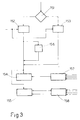
- Block 151 to which the signal from sensor 107 is supplied, determines the presence of said signal, i.e. whether sensor 107 is operating normally or not. In the event of normal operation, block 151 goes on to block 152, whereas, in the event of failure of sensor 107, block 151 goes on to block 153. Blocks 152 and 153 are supplied with the signal from sensor 112. Block 152 checks the relative angular position of pulley 108 and disk 109, and supplies blocks 154 and 155 with a signal corresponding to the absolute angular position of shaft 111 between 0 and 720°. Upon startup of engine 101, this signal is also supplied to block 156, which computes and stores in memory 104 the mechanical error of the stroke signal mentioned previously.
- Blocks 157 and 158 are supplied with signals relative to quantities and operating conditions of engine 101, in this case, from sensors 114, 116, 117 and 118.
- Block 157 computes the spark lead, and is connected to block 154, which, on the basis of the signals supplied to it, enables electronic ignition via the distributor or by controlling a coil for each cylinder or each pair of cylinders.
- Block 158 computes injection time cylinder by cylinder, and supplies block 155 with an injection time signal, and a signal relative to the stroke of the cylinder to be injected, for enabling electronic injection accordingly.
- Blocks 154 and 157 represent an electronic ignition system, and blocks 155 and 158 an electronic injection system.
- Block 153 computes a presumed angular position of shaft 111 between 0 and 720°, on the basis of the signals received from sensor 112 and corrected in accordance with the stored mechanical error.
- the output signal from block 153 is sent to blocks 154 and 155, and, though obviously not as accurate as the output signal from block 152, nevertheless provides for enabling ignition and injection and running the vehicle.
Landscapes
- Engineering & Computer Science (AREA)
- Chemical & Material Sciences (AREA)
- Combustion & Propulsion (AREA)
- Mechanical Engineering (AREA)
- General Engineering & Computer Science (AREA)
- Physics & Mathematics (AREA)
- Electromagnetism (AREA)
- Ignition Installations For Internal Combustion Engines (AREA)
- Combined Controls Of Internal Combustion Engines (AREA)
- Electrical Control Of Ignition Timing (AREA)
- Control Of Transmission Device (AREA)
Claims (8)
- Système de repérage de position angulaire dans un moteur à combustion interne, comprenant :un système d'allumage électronique (155 et 157) ;un système d'injection électronique (156 et 158) ;une poulie (108) montée sur l'arbre de commande (111) du moteur (101), et définie par une roue dentée comportant un certain nombre de premières dents (134) et un espace défini par l'absence de certaines de ces premières dents (134) ;un premier capteur (107) pour détecter les premières dents (134) et par conséquent, les positions angulaires prédéterminées de cet arbre de commande (111) ;caractérisé par le fait de comprendre :un second arbre (110) en rotation à la moitié de la vitesse de, mais en synchronisation avec, l'arbre de commande (111) ;un disque (109) monté sur le second arbre (110), comportant des interruptions espacées de façon égale (135 et 136) dont une première interruption est identifiable du fait d'être différente des autres ;un second capteur (112) pour détecter les interruptions (135 et 136) et, par conséquent, les positions angulaires prédéterminées du second arbre (110) ;des premiers moyens (156) pour calculer, lors du démarrage du moteur (101), la position angulaire relative réelle de la poulie (108) et du disque (109), en détectant simultanément l'espace sur la poulie (108) et la première interruption (136) sur le disque (109) ; et pour stocker cette position angulaire réelle dans une mémoire permanente (104) ;des seconds moyens (152) pour calculer la position angulaire absolue de l'arbre de commande (111), en fonction des signaux provenant des capteurs (107 et 112), et validant ou mettant en circuit le système d'allumage électronique (155 et 157) et le système d'injection électronique (156 et 158) ; etdes troisièmes moyens (153) qui, en l'absence d'un signal provenant du premier capteur (107), et en fonction du signal provenant du second capteur (112) et du signal traité par les premiers moyens (156), assurent le calcul de la position angulaire présumée de l'arbre de commande (111) pour valider ou mettre en circuit le système d'allumage (155 et 157) et le système d'injection (156 et 158).
- Système de repérage selon la revendication 1, caractérisé par le fait qu'il comprend quatre moyens (151) pour déterminer le fonctionnement correct du premier capteur (107) et mettre en circuit les seconds moyens (152) dans le cas d'un fonctionnement normal et les troisièmes moyens (153) dans le cas de panne du premier capteur (107).
- Système de repérage selon la revendication 1 et/ou 2, caractérisé par le fait de comprendre un compteur (103) pour compter et mémoriser le nombre de premières dents (134) au-dessus de la rotation 720° de l'arbre de commande (111) ; le comptage commençant à partir de la première de ces premières dents (134), avec le premier capteur (107) positionné en face de l'espace sur la poulie (108) et le second capteur (112) faisant simultanément face à la première interruption (136).
- Système de repérage selon la revendication 3, caractérisé par le fait que la poulie (108) consiste en une roue dentée ayant 60 moins 2 premières dents espacées de façon égale (134) ; l'espacement étant défini par l'absence de deux de ces premières dents (134).
- Système de repérage selon la revendication 4, caractérisé par le fait que pour un moteur à quatre cylindres, le disque (109) présente trois secondes dents (135 et 136) à 120° l'une de l'autre, dont deux dents s'étendent sur le même arc, et la troisième dent sur un arc plus grand de 90°.
- Système de repérage selon la revendication 4, caractérisé par le fait que, pour un moteur à quatre cylindres, le disque (109) présente une première ouverture tous les 90°, et une seconde ouverture proche de l'une des premières ouvertures pour permettre son identification par le second capteur (112).
- Système de repérage selon la revendication 4, caractérisé par le fait que, pour un moteur à quatre cylindres, le disque (109) présente quatre ouvertures, dont l'une diffère dans sa grandeur par rapport aux autres.
- Système de repérage selon la revendication 4, caractérisé par le fait que, pour un moteur à quatre cylindres, le disque (109) présente trois ouvertures à 120° l'une de l'autre dont deux s'étendent sur le même arc, et la troisième sur un arc plus grand de 90°.
Applications Claiming Priority (2)
| Application Number | Priority Date | Filing Date | Title |
|---|---|---|---|
| ITTO910050 | 1991-01-29 | ||
| ITTO910050A IT1245012B (it) | 1991-01-29 | 1991-01-29 | Sistema di identificazione delle fasi di un motore endotermico |
Publications (3)
| Publication Number | Publication Date |
|---|---|
| EP0497237A2 EP0497237A2 (fr) | 1992-08-05 |
| EP0497237A3 EP0497237A3 (en) | 1993-05-26 |
| EP0497237B1 true EP0497237B1 (fr) | 1996-12-11 |
Family
ID=11408831
Family Applications (1)
| Application Number | Title | Priority Date | Filing Date |
|---|---|---|---|
| EP92101247A Expired - Lifetime EP0497237B1 (fr) | 1991-01-29 | 1992-01-27 | Système de repérage de position angulaire dans un moteur à combustion interne |
Country Status (4)
| Country | Link |
|---|---|
| EP (1) | EP0497237B1 (fr) |
| DE (1) | DE69215703T2 (fr) |
| ES (1) | ES2097824T3 (fr) |
| IT (1) | IT1245012B (fr) |
Families Citing this family (6)
| Publication number | Priority date | Publication date | Assignee | Title |
|---|---|---|---|---|
| GB2272973B (en) * | 1992-11-14 | 1996-04-24 | Delco Electronics Corp | Method and apparatus for controlling a vehicle engine |
| DE4313331A1 (de) * | 1993-04-23 | 1994-10-27 | Bosch Gmbh Robert | Verfahren zur Auslösung von zur Winkellage eines rotierenden Teils abhängigen Vorgängen |
| DE59405391D1 (de) * | 1994-05-17 | 1998-04-09 | Siemens Ag | Verfahren zur Notlaufsteuerung einer Brennkraftmaschine |
| DE19750024B4 (de) * | 1997-11-12 | 2008-05-15 | Robert Bosch Gmbh | Verfahren zum Ermitteln eines Anbaufehlers eines Geberrades und Verfahren zur Steuerung der Kraftstoffzumessung einer Brennkraftmaschine |
| DE19927191A1 (de) * | 1999-06-15 | 2000-12-21 | Bosch Gmbh Robert | Verfahren zur Korrektur eines Winkelfehlers eines Absolutwinkelgebers |
| CA2560262A1 (fr) * | 2004-03-29 | 2005-10-13 | Southwest Research Institute | Procede d'identification et de poursuite de position du vilebrequin du moteur applicable a des signaux de la came et du vilebrequin presentant des configurations arbitraires |
Family Cites Families (9)
| Publication number | Priority date | Publication date | Assignee | Title |
|---|---|---|---|---|
| FR2171626A5 (fr) * | 1972-02-09 | 1973-09-21 | Schlumberger Compteurs | |
| FR2374528A1 (fr) * | 1976-12-17 | 1978-07-13 | Cii | Systeme d'allumage electronique et moteur a combustion interne equipe d'un tel systeme |
| FR2446467A1 (fr) * | 1979-01-09 | 1980-08-08 | Renault | Procede et appareillage de reperage de la position angulaire d'une piece animee d'un mouvement de rotation |
| US4373486A (en) * | 1981-01-09 | 1983-02-15 | Magnavox Government And Industrial Electronics Company | Rotational position and velocity sensing apparatus |
| DE3307833C2 (de) * | 1983-02-19 | 1993-12-16 | Bosch Gmbh Robert | Verfahren zum Anzeigen und/oder Speichern von Fehlern von Geberanordnungen an Brennkraftmaschinen |
| DE3634587A1 (de) * | 1986-10-10 | 1988-04-14 | Bosch Gmbh Robert | Zuendsystem fuer verbrennungsmotoren |
| JPS63154828A (ja) * | 1986-12-19 | 1988-06-28 | Fuji Heavy Ind Ltd | 内燃機関のクランク角度検出装置 |
| IT1239869B (it) * | 1990-01-26 | 1993-11-15 | Weber Srl | Sistema di tipo perfezionato per l'identificazione delle fasi di un motore endotermico |
| DE4005123A1 (de) * | 1990-02-17 | 1991-08-22 | Bosch Gmbh Robert | Zuendanlage fuer brennkraftmaschinen |
-
1991
- 1991-01-29 IT ITTO910050A patent/IT1245012B/it active IP Right Grant
-
1992
- 1992-01-27 DE DE69215703T patent/DE69215703T2/de not_active Expired - Fee Related
- 1992-01-27 EP EP92101247A patent/EP0497237B1/fr not_active Expired - Lifetime
- 1992-01-27 ES ES92101247T patent/ES2097824T3/es not_active Expired - Lifetime
Also Published As
| Publication number | Publication date |
|---|---|
| ITTO910050A0 (it) | 1991-01-29 |
| IT1245012B (it) | 1994-09-13 |
| EP0497237A2 (fr) | 1992-08-05 |
| ITTO910050A1 (it) | 1992-07-29 |
| ES2097824T3 (es) | 1997-04-16 |
| EP0497237A3 (en) | 1993-05-26 |
| DE69215703T2 (de) | 1997-05-22 |
| DE69215703D1 (de) | 1997-01-23 |
Similar Documents
| Publication | Publication Date | Title |
|---|---|---|
| US5447143A (en) | Device for detecting the position of at least one shaft which has a reference mark | |
| US4366794A (en) | Fuel injection control method for internal combustion engines | |
| US6016789A (en) | Apparatus for control of an internal combustion engine, especially for control of fuel injection and ignition | |
| US5156125A (en) | Engine control apparatus | |
| US4201161A (en) | Control system for internal combustion engine | |
| EP0663595B1 (fr) | Appareil et procédé pour déterminer la vitesse et la position d'un moteur avec un capteur unique | |
| JPH08506397A (ja) | 内燃機関における燃料噴射制御装置 | |
| US4616617A (en) | Method and arrangement for combustion chamber identification in an internal combustion engine | |
| EP0202813A2 (fr) | Dispositif de commande d'injection de carburant avec injection forcée durant la période de démarrage | |
| US4765306A (en) | Combustion engine stroke identification system | |
| JP4226082B2 (ja) | セグメントの検出方法 | |
| EP0497237B1 (fr) | Système de repérage de position angulaire dans un moteur à combustion interne | |
| CN1087393C (zh) | 内燃机汽缸识别装置 | |
| US4620519A (en) | Fuel injection system for internal combustion engine | |
| JPS6098146A (ja) | 内燃機関の燃料制御方法 | |
| EP0394290B1 (fr) | Procede et dispositif de detection de la direction de rotation du vilebrequin dans un moteur diesel | |
| GB2337136A (en) | Regulating an engine using a transmitter wheel with a reference mark | |
| JPH11257137A (ja) | エンジンの燃料噴射制御装置 | |
| EP0439194B1 (fr) | Système d'identification du temps de course de piston d'un moteur à combustion interne | |
| JP3963054B2 (ja) | 回転信号の異常検出装置 | |
| JP2689597B2 (ja) | エンジン出力制御装置 | |
| JP3060459B2 (ja) | 多気筒内燃機関の異常気筒検出装置 | |
| JPS59134377A (ja) | 電子制御エンジンの制御方法 | |
| KR100238736B1 (ko) | 기준 마크를 갖는 하나이상의 축 위치 검출장치 | |
| JP2856924B2 (ja) | エンジンの吸入空気量制御装置 |
Legal Events
| Date | Code | Title | Description |
|---|---|---|---|
| PUAI | Public reference made under article 153(3) epc to a published international application that has entered the european phase |
Free format text: ORIGINAL CODE: 0009012 |
|
| AK | Designated contracting states |
Kind code of ref document: A2 Designated state(s): DE ES FR GB |
|
| PUAL | Search report despatched |
Free format text: ORIGINAL CODE: 0009013 |
|
| AK | Designated contracting states |
Kind code of ref document: A3 Designated state(s): DE ES FR GB |
|
| 17P | Request for examination filed |
Effective date: 19931104 |
|
| RAP1 | Party data changed (applicant data changed or rights of an application transferred) |
Owner name: MAGNETI MARELLI S.P.A. |
|
| 17Q | First examination report despatched |
Effective date: 19950626 |
|
| GRAG | Despatch of communication of intention to grant |
Free format text: ORIGINAL CODE: EPIDOS AGRA |
|
| GRAH | Despatch of communication of intention to grant a patent |
Free format text: ORIGINAL CODE: EPIDOS IGRA |
|
| GRAH | Despatch of communication of intention to grant a patent |
Free format text: ORIGINAL CODE: EPIDOS IGRA |
|
| GRAA | (expected) grant |
Free format text: ORIGINAL CODE: 0009210 |
|
| AK | Designated contracting states |
Kind code of ref document: B1 Designated state(s): DE ES FR GB |
|
| REF | Corresponds to: |
Ref document number: 69215703 Country of ref document: DE Date of ref document: 19970123 |
|
| ET | Fr: translation filed | ||
| REG | Reference to a national code |
Ref country code: ES Ref legal event code: FG2A Ref document number: 2097824 Country of ref document: ES Kind code of ref document: T3 |
|
| PLAV | Examination of admissibility of opposition |
Free format text: ORIGINAL CODE: EPIDOS OPEX |
|
| PLBI | Opposition filed |
Free format text: ORIGINAL CODE: 0009260 |
|
| 26 | Opposition filed |
Opponent name: ROBERT BOSCH GMBH Effective date: 19970909 |
|
| PLBF | Reply of patent proprietor to notice(s) of opposition |
Free format text: ORIGINAL CODE: EPIDOS OBSO |
|
| PLBF | Reply of patent proprietor to notice(s) of opposition |
Free format text: ORIGINAL CODE: EPIDOS OBSO |
|
| PLBF | Reply of patent proprietor to notice(s) of opposition |
Free format text: ORIGINAL CODE: EPIDOS OBSO |
|
| PLBO | Opposition rejected |
Free format text: ORIGINAL CODE: EPIDOS REJO |
|
| PLBN | Opposition rejected |
Free format text: ORIGINAL CODE: 0009273 |
|
| STAA | Information on the status of an ep patent application or granted ep patent |
Free format text: STATUS: OPPOSITION REJECTED |
|
| 27O | Opposition rejected |
Effective date: 20000414 |
|
| REG | Reference to a national code |
Ref country code: GB Ref legal event code: IF02 |
|
| PGFP | Annual fee paid to national office [announced via postgrant information from national office to epo] |
Ref country code: FR Payment date: 20030128 Year of fee payment: 12 |
|
| PGFP | Annual fee paid to national office [announced via postgrant information from national office to epo] |
Ref country code: GB Payment date: 20030129 Year of fee payment: 12 |
|
| PGFP | Annual fee paid to national office [announced via postgrant information from national office to epo] |
Ref country code: ES Payment date: 20030130 Year of fee payment: 12 |
|
| PGFP | Annual fee paid to national office [announced via postgrant information from national office to epo] |
Ref country code: DE Payment date: 20030331 Year of fee payment: 12 |
|
| PG25 | Lapsed in a contracting state [announced via postgrant information from national office to epo] |
Ref country code: GB Free format text: LAPSE BECAUSE OF NON-PAYMENT OF DUE FEES Effective date: 20040127 |
|
| PG25 | Lapsed in a contracting state [announced via postgrant information from national office to epo] |
Ref country code: ES Free format text: LAPSE BECAUSE OF NON-PAYMENT OF DUE FEES Effective date: 20040128 |
|
| PG25 | Lapsed in a contracting state [announced via postgrant information from national office to epo] |
Ref country code: DE Free format text: LAPSE BECAUSE OF NON-PAYMENT OF DUE FEES Effective date: 20040803 |
|
| GBPC | Gb: european patent ceased through non-payment of renewal fee |
Effective date: 20040127 |
|
| PG25 | Lapsed in a contracting state [announced via postgrant information from national office to epo] |
Ref country code: FR Free format text: LAPSE BECAUSE OF NON-PAYMENT OF DUE FEES Effective date: 20040930 |
|
| REG | Reference to a national code |
Ref country code: FR Ref legal event code: ST |
|
| REG | Reference to a national code |
Ref country code: ES Ref legal event code: FD2A Effective date: 20040128 |