EP0497257B1 - Dispositif de tronçonnage - Google Patents
Dispositif de tronçonnage Download PDFInfo
- Publication number
- EP0497257B1 EP0497257B1 EP92101304A EP92101304A EP0497257B1 EP 0497257 B1 EP0497257 B1 EP 0497257B1 EP 92101304 A EP92101304 A EP 92101304A EP 92101304 A EP92101304 A EP 92101304A EP 0497257 B1 EP0497257 B1 EP 0497257B1
- Authority
- EP
- European Patent Office
- Prior art keywords
- blade plate
- cutting
- holder
- plate
- recess
- Prior art date
- Legal status (The legal status is an assumption and is not a legal conclusion. Google has not performed a legal analysis and makes no representation as to the accuracy of the status listed.)
- Expired - Lifetime
Links
Images

Classifications
-
- B—PERFORMING OPERATIONS; TRANSPORTING
- B23—MACHINE TOOLS; METAL-WORKING NOT OTHERWISE PROVIDED FOR
- B23B—TURNING; BORING
- B23B27/00—Tools for turning or boring machines; Tools of a similar kind in general; Accessories therefor
- B23B27/08—Cutting tools with blade- or disc-like main parts
-
- B—PERFORMING OPERATIONS; TRANSPORTING
- B23—MACHINE TOOLS; METAL-WORKING NOT OTHERWISE PROVIDED FOR
- B23B—TURNING; BORING
- B23B2205/00—Fixation of cutting inserts in holders
- B23B2205/02—Fixation using an elastically deformable clamping member
Definitions
- the invention relates to a parting device for rotating workpieces with a blade plate which is fastened to a receptacle adapted to the blade plate to support it, and with a lancing plate which can be inserted into a recess in the blade plate.
- a parting device of this type is e.g. described in EP 0 059 602 A1.
- a blade plate which is designed as a rectangular, elongated strip.
- This bar is generally connected to a receptacle via a dovetail guide and thus in Longitudinal direction adjustable to this.
- the holder itself serves as a clamping part and is used, for example, in a tool holder of a lathe. The lancing plate is clamped into a recess in the blade plate on the front.
- a disadvantage of these known parting-off devices is that they are not very pressure-stable. In particular at higher side pressures, the blade plate dodges, so that the cut is inaccurate, e.g. crowned, will.
- parting device itself is not adjustable in height. For precise adjustment to the center of the workpiece, corresponding shims must therefore be inserted between the holder and the tool holder. If this setting is not made exactly or changes occur during operation, e.g. due to wear on the lancing plate, and if the lancing plate is no longer exactly centered, there is a risk of the lancing plate breaking, which is generally made of hard metal and is therefore very brittle.
- GB-A-980 364 shows a parting device with fixed parting plates which are arranged on a propeller-like plate.
- the propeller-like plate is attached to a solid block.
- Such a configuration is not suitable for VDI machines; in particular, it is not very robust and cannot be precisely adjusted.
- the present invention is therefore based on the object of providing a parting-off device of the type mentioned at the outset which, due to its design, has a longer service life, in particular which is more robust and which can be adjusted better to the respective operating conditions and thus works more precisely.
- the height of the lancing plate arranged in the blade plate can be optimally adjusted. This means you can’t just start working, but also make corresponding height corrections in a simple manner during operation by adjusting the relative rotational position between the blade plate and the holder.
- a simple rotatability of the blade plate and a high stability is achieved by the at least approximately disk-shaped design of the blade plate and its storage in the receptacle via the central hub.
- One of the main advantages of this embodiment is that the service life is significantly extended, because the blade plate and the lancing plate are not subjected to such high loads, since optimum adjustment is always made possible in a simple manner by simple readjustment.
- the device according to the invention can of course not only be used for parting, but also for parting in rotating workpieces.
- the blade plate can be adjusted in relation to the holder in various ways.
- the stop in the receptacle is designed as an adjusting member is.
- the setting member can have a pivot pin with an eccentric head.
- an eccentric head can be used here for the adjustment and readjustment, in which the relative position between the blade plate and the receptacle is changed by the adjustment of the eccentricity.
- the receiving disc can support the blade plate very well over a further area, so that it does not cantilever too far, which largely eliminates the risk of bending.
- the inclusion can basically be taken for granted also form in one piece.
- they will generally be made in two parts, the connection between the two parts being arbitrary.
- a detachable connection for example via screws, will generally be provided.
- the setting or adjustment of the relative rotational position of the blade plate with respect to the receptacle can be carried out by means of an adjusting element arranged on the rear of the pivot pin.
- the rotary piston itself can be provided with an internal hexagon hole at its rear end in a simple manner.
- the pivot pin can be locked in the desired position by means of a clamping screw which is arranged in the receptacle.
- a clamping screw which is arranged in the receptacle.
- other locking elements are also possible if necessary.
- a very advantageous development of the invention is that the blade plate is arranged in the receptacle in such a way that its central axis is not set state lies above the central axis of the receptacle or the workpiece to be machined.
- the offset arrangement of the central axes according to the invention which can be between 0.2 and 0.4 mm if necessary, ensures that the blade plate will generally be too high in its seat. For this reason, it is only rotated downwards for precise adjustment, which will in any case leave a sufficiently large clearance angle, or it may even become even larger.
- This center offset can be designed differently depending on and adapting to the structural conditions and the type of connection between the receptacle and the blade plate.
- the recess in the blade plate can be arranged so that the front tip of the lancing plate is above the center line of the workpiece to be machined in the non-adjusted state. This means that the recess should be placed approximately 0.2-0.4 mm higher in the blade plate.
- a further advantageous embodiment of the invention can consist in that the lancing plate is press-fitted into the recess in the blade plate.
- the cutout according to the invention can be designed in a simple manner as a slot or as a groove with two slot or groove walls running at least approximately parallel to one another. The lancing plate is then clamped between the walls.
- a press fit can be done in a simple manner achieve that the recess tapers towards the rear, that is, that the diaphragm walls are too slightly tapered towards the rear.
- the lancing plate has parallel clamping surfaces.
- the blade plate can also be designed as a reversible plate with at least two cutouts.
- a defective recess e.g. Too much play due to wear
- the service life of the blade plate can be doubled.
- the blade plate according to the invention can also advantageously be used as a side milling cutter. All that is required is to provide the blade plate with even more cutouts on the circumference, e.g. 3, 4, 6 or more, and clamp them in the recesses corresponding to the hard metal plate.
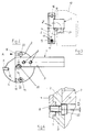
- the parting device has as essential components a receptacle 1, which consists of a front receiving disk 2 and a rear receiving part 3, a blade plate 4 and a lancing plate 5. Via two cheese head screws 6, the receiving disc 2 is connected to the rear receiving part 3, which is designed in the form of a square, elongated block.
- the receiving disk 2 has a semicircular shape when viewed from the side, or the semicircle is enlarged somewhat beyond the central axis.
- the blade plate On the side facing away from the receiving part 3, the blade plate is placed on the receiving disc 2.
- this has a hub 7 with a threaded bore 8.
- the hub 7 is inserted into a central bearing bore 9 in the receiving disc 2.
- the peripheral walls of the receiving disc 2 and the blade plate 4 are partially congruent.
- the blade plate 4 only projects by the depth of cut at the front over the receiving disc 2 (see FIG. 2).
- the lancing plate 5 is clamped with a press fit into a recess 10 in the peripheral wall of the blade plate 4.
- the recess 10 tapers towards the back correspondingly slightly, so that the lancing plate 5 is pushed from the front or outside backwards into the recess 10 until it is clamped.
- a further recess 10 ′ is arranged in the blade plate 4 diametrically to the recess 10.
- a pivot pin 11 is inserted, on the front part of which protrudes from the receiving disc, an eccentric head 12 is arranged.
- the eccentric head 12 lies against a stop edge 13 of the blade plate 4.
- the rear of the pivot pin 11 has an adjusting member which is designed as a hexagon socket 14 in the pivot pin 11 itself.
- two receiving bores 22 for a pivot pin 11 can be provided opposite one another in the receiving disc 3 (see FIG. 1), the pivot pin 11 then being inserted into the respective bore.
- the end bore 16 for the clamping screw 15 is double.
- the receiving disk 3 has contact edges 17 and 18 on the side facing the receiving part 1, but these are arranged such that the receiving disk 3 lies 0.3 mm above the central axis of the clamping or the workpiece to be machined (see enlarged detail according to FIG. 6 ).
- the parting device is inserted as a whole into a tool holder 19.
- the tool holder 19 is shown in dashed lines in FIGS. 1 and 3.
- the blade plate 4, in which the desired lancing plate 5 is clamped, is connected by a central bearing screw 20.
- the bearing screw 20 is inserted from the rear through the bearing bore 9 in the receiving washer 2 and screwed into the threaded bore 8 of the blade plate 4.
- the position of the blade plate 4 to the receiving disc 2 is chosen so that the eccentric head 12 of the pivot pin 11 rests on the stop edge 13. In this way, a rough setting is achieved.
- the fine adjustment is carried out after loosening the clamping screw 15 by turning the pivot pin 11.
- the hexagon socket 14 of the pivot pin 11 a hexagon wrench is used, with which the eccentric head 12 is rotated accordingly and thus an adjustment or radial rotation of the blade plate 4 relative to the receiving disc 2 takes place (see arrow direction in Fig. 1). In this way, the lancing plate 5 can be adjusted to the exact center position.
- the recess 10 or 10 'in the blade plate 4 can be too high, e.g. 0.3 mm are introduced in such a way that, after inserting a lancing plate 5 into the recess 10, its front tip in the non-adjusted state lies above the center line of the workpiece to be machined (see the dashed line in FIG. 4).
Landscapes
- Engineering & Computer Science (AREA)
- Mechanical Engineering (AREA)
- Finish Polishing, Edge Sharpening, And Grinding By Specific Grinding Devices (AREA)
- Perforating, Stamping-Out Or Severing By Means Other Than Cutting (AREA)
- Absorbent Articles And Supports Therefor (AREA)
- Electrical Discharge Machining, Electrochemical Machining, And Combined Machining (AREA)
- Sawing (AREA)
- Confectionery (AREA)
- Seal Device For Vehicle (AREA)
- Saccharide Compounds (AREA)
Claims (12)
- Dispositif de décolletage de pièces rotatives, comportant une plaque de lame (4) qui est fixée à une monture (1) ajustée à la plaque de lame (4) pour l'épauler, et une plaquette de coupe (5) se logeant dans un évidement (10) de la plaque de lame (4), caractérisé en ce que la plaque de lame (4) est raccordée à la monture (1) de manière pivotante dans un plan, perpendiculairement à la direction de plongée, la position relative de pivotement de ladite plaque (4) par rapport à la monture (1) étant réglable, en ce que la plaque de lame (4) est au moins approximativement en forme de disque, en ce que ledit évidement (10) est disposé dans la zone d'une paroi circonférentielle de la plaque de lame (4), en ce que la plaque de lame (4) est pourvue d'un moyeu (7) qui est logé dans un alésage récepteur (9) d'une partie avant de la monture (1), agencée en plaque de monture (2), la plaque de monture ayant une forme au moins partiellement ou approximativement adaptée à la plaque de lame (4) pour l'épauler, et en ce que la plaque de lame (4) s'appuie par au moins un bord de butée (13) contre une butée de la monture (1).
- Dispositif selon la revendication 1, caractérisé en ce que ladite butée est formée par un élément de réglage (12) sur la monture (1).
- Dispositif selon la revendication 2, caractérisé en ce que l'élément de réglage comporte un boulon rotatif (11) pourvu d'une tête excentrique (12).
- Dispositif selon la revendication 3, caractérisé en ce que le boulon rotatif (11) est pourvu d'un organe de manoeuvre (14) sur son côté arrière.
- Dispositif selon la revendication 3 ou 4, caractérisé en ce que le boulon rotatif (11) est susceptible d'être bloqué au moyen d'une vis de blocage (15) disposée dans la monture (1).
- Dispositif selon l'une des revendications 1 à 5, caractérisé en ce que la plaque de monture (2) a au moins approximativement une forme semi-circulaire.
- Dispositif selon l'une des revendications 1 à 6, caractérisé en ce que la monture (1) est en deux parties dont la partie avant servant de plaque de monture (2) est fixée par des vis (6) et des bords d'appui (17, 18) à la partie arrière (3) de la monture (1).
- Dispositif selon l'une des revendications 1 à 7, caractérisé en ce que la plaque de lame (4) est disposée sur la monture (1) de telle manière que son axe central, dans l'état non réglé, se trouve au-dessus de l'axe central de la monture (1) ou de la pièce à usiner.
- Dispositif selon les revendications 7 et 8, caractérisé en ce que les bords d'appui (17, 18) de la partie avant (2) de la monture (1), contre lesquels s'appuie la plaque de lame (4), sont décentrés par rapport à l'axe central de la pièce à usiner.
- Dispositif selon l'une des revendications 1 à 9, caractérisé en ce que ledit évidement (10) est disposé dans la plaque de lame (4) de telle manière que la pointe antérieure de la plaquette de coupe (5), dans l'état non réglé, se trouve au-dessus de l'axe central de la pièce à usiner.
- Dispositif selon l'une des revendications 1 à 10, caractérisé en ce que la plaquette de coupe (5) est montée dans l'évidement (10) de la plaque de lame (4) par ajustement pressé, l'évidement (10) étant rétréci vers l'arrière le cas échéant.
- Dispositif selon l'une des revendications 1 à 11, caractérisé en ce que la plaque de lame (4) est agencée en plaque tournante, comportant au moins deux évidements (10, 10').
Applications Claiming Priority (2)
| Application Number | Priority Date | Filing Date | Title |
|---|---|---|---|
| DE4102826 | 1991-01-31 | ||
| DE4102826A DE4102826A1 (de) | 1991-01-31 | 1991-01-31 | Abstechvorrichtung |
Publications (3)
| Publication Number | Publication Date |
|---|---|
| EP0497257A2 EP0497257A2 (fr) | 1992-08-05 |
| EP0497257A3 EP0497257A3 (en) | 1992-11-25 |
| EP0497257B1 true EP0497257B1 (fr) | 1995-04-12 |
Family
ID=6424057
Family Applications (1)
| Application Number | Title | Priority Date | Filing Date |
|---|---|---|---|
| EP92101304A Expired - Lifetime EP0497257B1 (fr) | 1991-01-31 | 1992-01-28 | Dispositif de tronçonnage |
Country Status (4)
| Country | Link |
|---|---|
| EP (1) | EP0497257B1 (fr) |
| AT (1) | ATE120991T1 (fr) |
| DE (2) | DE4102826A1 (fr) |
| ES (1) | ES2071356T3 (fr) |
Cited By (3)
| Publication number | Priority date | Publication date | Assignee | Title |
|---|---|---|---|---|
| EP1666179A2 (fr) | 2004-12-01 | 2006-06-07 | Präzisions-Drehteile Löcher GmbH | Plaquette de coupe pour le décolletage et tronçonnage des pièces et porte plaquette |
| KR20170045271A (ko) * | 2014-09-05 | 2017-04-26 | 글리슨-파아우터 마쉰넨파브리크 게엠베하 | 치형부를 기계가공하기 위한 방법, 기계가공 툴 및 머신 툴 |
| KR20200114318A (ko) * | 2019-03-28 | 2020-10-07 | 박성혁 | 베벨기어 절삭가공툴 및 그 절삭가공툴을 이용한 베벨기어의 가공방법 |
Families Citing this family (3)
| Publication number | Priority date | Publication date | Assignee | Title |
|---|---|---|---|---|
| EP2082820A3 (fr) * | 2008-01-23 | 2009-09-09 | Präzisions-Drehteile Löcher GmbH | Outil d'enlèvement de copeaux |
| DE202010009471U1 (de) * | 2010-06-14 | 2011-10-10 | Hartmetall-Werkzeugfabrik Paul Horn Gmbh | Werkzeug für die spanende Bearbeitung, insbesondere Drehwerkzeug |
| BR112019004126B1 (pt) | 2016-09-06 | 2022-07-12 | Iscar Ltd | Adaptador de elemento de inserção para particionar que tem um eixo geométrico de índice de adaptador |
Family Cites Families (8)
| Publication number | Priority date | Publication date | Assignee | Title |
|---|---|---|---|---|
| DE346157C (de) * | 1920-07-21 | 1921-12-24 | Franz Kuessner & Co | Drehstahlhalter |
| US2625068A (en) * | 1951-02-10 | 1953-01-13 | John R Smith | Skiving tool holding means for automatic screw machines |
| US2907099A (en) * | 1956-02-01 | 1959-10-06 | Cone Automatic Mach Co Inc | Metal cutting tool |
| GB980364A (en) * | 1962-12-05 | 1965-01-13 | Brierley Zachry | Improvements in and relating to machine tools |
| DE2018469A1 (de) * | 1970-04-17 | 1971-11-11 | Schmidt F | Einstechwerkzeug für verschiedene Nutbreiten |
| DE7820161U1 (de) * | 1978-07-05 | 1978-10-12 | Moessel, Georg | Drehmeissel |
| IL62278A (en) * | 1981-03-03 | 1984-10-31 | Iscar Ltd | Rotational cutting tool |
| US5044838A (en) * | 1990-04-26 | 1991-09-03 | Brookfield Richard A | Tool holding circular toothed blades stationary while cutting or grooving rotating work |
-
1991
- 1991-01-31 DE DE4102826A patent/DE4102826A1/de not_active Withdrawn
-
1992
- 1992-01-28 EP EP92101304A patent/EP0497257B1/fr not_active Expired - Lifetime
- 1992-01-28 DE DE59201859T patent/DE59201859D1/de not_active Expired - Lifetime
- 1992-01-28 ES ES92101304T patent/ES2071356T3/es not_active Expired - Lifetime
- 1992-01-28 AT AT92101304T patent/ATE120991T1/de not_active IP Right Cessation
Cited By (3)
| Publication number | Priority date | Publication date | Assignee | Title |
|---|---|---|---|---|
| EP1666179A2 (fr) | 2004-12-01 | 2006-06-07 | Präzisions-Drehteile Löcher GmbH | Plaquette de coupe pour le décolletage et tronçonnage des pièces et porte plaquette |
| KR20170045271A (ko) * | 2014-09-05 | 2017-04-26 | 글리슨-파아우터 마쉰넨파브리크 게엠베하 | 치형부를 기계가공하기 위한 방법, 기계가공 툴 및 머신 툴 |
| KR20200114318A (ko) * | 2019-03-28 | 2020-10-07 | 박성혁 | 베벨기어 절삭가공툴 및 그 절삭가공툴을 이용한 베벨기어의 가공방법 |
Also Published As
| Publication number | Publication date |
|---|---|
| ES2071356T3 (es) | 1995-06-16 |
| EP0497257A2 (fr) | 1992-08-05 |
| DE4102826A1 (de) | 1992-08-06 |
| ATE120991T1 (de) | 1995-04-15 |
| EP0497257A3 (en) | 1992-11-25 |
| DE59201859D1 (de) | 1995-05-18 |
Similar Documents
| Publication | Publication Date | Title |
|---|---|---|
| DE2339873C2 (de) | Anordnung zum Einstellen und Befestigen eines ein Schneidplättchen tragenden Blocks in einer nutförmigen Aufnahme im Werkzeugkörper eines spanabhebenden Werkzeugs | |
| DE4032176C2 (de) | Scheibenschneider | |
| EP0182290A2 (fr) | Tête de fraisage | |
| WO2000052303A1 (fr) | Systeme a changement de porte-outil | |
| WO1990014186A1 (fr) | Outil a magasin interchangeable deplaçable | |
| WO2010083541A1 (fr) | Outil de fraisage à disque et élément de coupe | |
| DE68906085T2 (de) | Fraeswerkzeug und kassette dafuer. | |
| EP0410104B1 (fr) | Outil d'usinage par enlèvement de copeaux | |
| EP2895289B1 (fr) | Outil d'usinage de pièces par enlèvement de matière | |
| DE9107615U1 (de) | Zweischneidiges Gesenkwerkzeug zum Fräsen und Bohren | |
| DE2533495C3 (de) | Bohrstange | |
| EP0544658B1 (fr) | Outil de coupe servant a usiner les contours interieurs et exterieurs de pieces a usiner | |
| EP2200775A1 (fr) | Alésoir | |
| EP0497257A2 (fr) | Dispositif de tronçonnage | |
| DE102017212200B4 (de) | Zerspanungswerkzeug mit einem an einem grundkörper einstellbar gehaltenen schneideinsatz | |
| DE3942585A1 (de) | Klemmhalter fuer zweischneiden-wendeschneidplatten | |
| EP0033086B1 (fr) | Outil de perçage avec plaquette indexable | |
| EP3292931B1 (fr) | Outil, notamment pour l'usinage de pièces à enlèvement de copeaux | |
| CH652951A5 (de) | Werkzeug zum aufbohren und plansenken. | |
| DE3408354A1 (de) | Profilmesserkopf | |
| DE102016205658B3 (de) | Schneidwerkzeug mit einem an einem trägerkörper durch eine spannpratze lösbar befestigtem schneidkörper | |
| DE9203801U1 (de) | Einstellbarer Ausdrehkopf für kleine Durchmesser | |
| DE9108553U1 (de) | Messerkopf, insbesondere Hobelkopf | |
| DE8401019U1 (de) | Bohr- und Ausdrehwerkzeug | |
| DE9102162U1 (de) | Abstechvorrichtung |
Legal Events
| Date | Code | Title | Description |
|---|---|---|---|
| PUAI | Public reference made under article 153(3) epc to a published international application that has entered the european phase |
Free format text: ORIGINAL CODE: 0009012 |
|
| AK | Designated contracting states |
Kind code of ref document: A2 Designated state(s): AT BE CH DE ES FR GB IT LI NL SE |
|
| PUAL | Search report despatched |
Free format text: ORIGINAL CODE: 0009013 |
|
| AK | Designated contracting states |
Kind code of ref document: A3 Designated state(s): AT BE CH DE ES FR GB IT LI NL SE |
|
| 17P | Request for examination filed |
Effective date: 19930120 |
|
| 17Q | First examination report despatched |
Effective date: 19931029 |
|
| GRAA | (expected) grant |
Free format text: ORIGINAL CODE: 0009210 |
|
| AK | Designated contracting states |
Kind code of ref document: B1 Designated state(s): AT BE CH DE ES FR GB IT LI NL SE |
|
| PG25 | Lapsed in a contracting state [announced via postgrant information from national office to epo] |
Ref country code: NL Free format text: LAPSE BECAUSE OF FAILURE TO SUBMIT A TRANSLATION OF THE DESCRIPTION OR TO PAY THE FEE WITHIN THE PRESCRIBED TIME-LIMIT Effective date: 19950412 Ref country code: BE Effective date: 19950412 |
|
| REF | Corresponds to: |
Ref document number: 120991 Country of ref document: AT Date of ref document: 19950415 Kind code of ref document: T |
|
| REF | Corresponds to: |
Ref document number: 59201859 Country of ref document: DE Date of ref document: 19950518 |
|
| REG | Reference to a national code |
Ref country code: ES Ref legal event code: FG2A Ref document number: 2071356 Country of ref document: ES Kind code of ref document: T3 |
|
| ITF | It: translation for a ep patent filed | ||
| GBT | Gb: translation of ep patent filed (gb section 77(6)(a)/1977) |
Effective date: 19950612 |
|
| PG25 | Lapsed in a contracting state [announced via postgrant information from national office to epo] |
Ref country code: SE Effective date: 19950712 |
|
| ET | Fr: translation filed | ||
| NLV1 | Nl: lapsed or annulled due to failure to fulfill the requirements of art. 29p and 29m of the patents act | ||
| PLBE | No opposition filed within time limit |
Free format text: ORIGINAL CODE: 0009261 |
|
| STAA | Information on the status of an ep patent application or granted ep patent |
Free format text: STATUS: NO OPPOSITION FILED WITHIN TIME LIMIT |
|
| 26N | No opposition filed | ||
| REG | Reference to a national code |
Ref country code: GB Ref legal event code: IF02 |
|
| REG | Reference to a national code |
Ref country code: CH Ref legal event code: PCAR Free format text: CABINET ROLAND NITHARDT CONSEILS EN PROPRIETE INDUSTRIELLE S.A.;Y-PARC RUE GALILEE;1400 YVERDON-LES-BAINS (CH) |
|
| PGFP | Annual fee paid to national office [announced via postgrant information from national office to epo] |
Ref country code: ES Payment date: 20100119 Year of fee payment: 19 |
|
| PGFP | Annual fee paid to national office [announced via postgrant information from national office to epo] |
Ref country code: DE Payment date: 20110202 Year of fee payment: 20 Ref country code: IT Payment date: 20101222 Year of fee payment: 20 Ref country code: FR Payment date: 20110214 Year of fee payment: 20 Ref country code: AT Payment date: 20110121 Year of fee payment: 20 |
|
| PGFP | Annual fee paid to national office [announced via postgrant information from national office to epo] |
Ref country code: GB Payment date: 20110127 Year of fee payment: 20 Ref country code: CH Payment date: 20110413 Year of fee payment: 20 |
|
| REG | Reference to a national code |
Ref country code: DE Ref legal event code: R071 Ref document number: 59201859 Country of ref document: DE |
|
| REG | Reference to a national code |
Ref country code: DE Ref legal event code: R071 Ref document number: 59201859 Country of ref document: DE |
|
| REG | Reference to a national code |
Ref country code: CH Ref legal event code: PL |
|
| REG | Reference to a national code |
Ref country code: ES Ref legal event code: FD2A Effective date: 20120220 |
|
| REG | Reference to a national code |
Ref country code: GB Ref legal event code: PE20 Expiry date: 20120127 |
|
| REG | Reference to a national code |
Ref country code: AT Ref legal event code: MK07 Ref document number: 120991 Country of ref document: AT Kind code of ref document: T Effective date: 20120128 |
|
| PG25 | Lapsed in a contracting state [announced via postgrant information from national office to epo] |
Ref country code: ES Free format text: LAPSE BECAUSE OF NON-PAYMENT OF DUE FEES Effective date: 20110129 Ref country code: DE Free format text: LAPSE BECAUSE OF EXPIRATION OF PROTECTION Effective date: 20120129 |
|
| PG25 | Lapsed in a contracting state [announced via postgrant information from national office to epo] |
Ref country code: GB Free format text: LAPSE BECAUSE OF EXPIRATION OF PROTECTION Effective date: 20120127 |