EP0497294A2 - Séparateur à chambre toroidal - Google Patents
Séparateur à chambre toroidal Download PDFInfo
- Publication number
- EP0497294A2 EP0497294A2 EP92101402A EP92101402A EP0497294A2 EP 0497294 A2 EP0497294 A2 EP 0497294A2 EP 92101402 A EP92101402 A EP 92101402A EP 92101402 A EP92101402 A EP 92101402A EP 0497294 A2 EP0497294 A2 EP 0497294A2
- Authority
- EP
- European Patent Office
- Prior art keywords
- container
- annular chamber
- chamber separator
- ring
- annular
- Prior art date
- Legal status (The legal status is an assumption and is not a legal conclusion. Google has not performed a legal analysis and makes no representation as to the accuracy of the status listed.)
- Granted
Links
Images
Classifications
-
- B—PERFORMING OPERATIONS; TRANSPORTING
- B01—PHYSICAL OR CHEMICAL PROCESSES OR APPARATUS IN GENERAL
- B01D—SEPARATION
- B01D21/00—Separation of suspended solid particles from liquids by sedimentation
- B01D21/0015—Controlling the inclination of settling devices
-
- B—PERFORMING OPERATIONS; TRANSPORTING
- B01—PHYSICAL OR CHEMICAL PROCESSES OR APPARATUS IN GENERAL
- B01D—SEPARATION
- B01D17/00—Separation of liquids, not provided for elsewhere, e.g. by thermal diffusion
-
- B—PERFORMING OPERATIONS; TRANSPORTING
- B01—PHYSICAL OR CHEMICAL PROCESSES OR APPARATUS IN GENERAL
- B01D—SEPARATION
- B01D17/00—Separation of liquids, not provided for elsewhere, e.g. by thermal diffusion
- B01D17/02—Separation of non-miscible liquids
- B01D17/0208—Separation of non-miscible liquids by sedimentation
-
- B—PERFORMING OPERATIONS; TRANSPORTING
- B01—PHYSICAL OR CHEMICAL PROCESSES OR APPARATUS IN GENERAL
- B01D—SEPARATION
- B01D17/00—Separation of liquids, not provided for elsewhere, e.g. by thermal diffusion
- B01D17/02—Separation of non-miscible liquids
- B01D17/0208—Separation of non-miscible liquids by sedimentation
- B01D17/0211—Separation of non-miscible liquids by sedimentation with baffles
-
- B—PERFORMING OPERATIONS; TRANSPORTING
- B01—PHYSICAL OR CHEMICAL PROCESSES OR APPARATUS IN GENERAL
- B01D—SEPARATION
- B01D21/00—Separation of suspended solid particles from liquids by sedimentation
- B01D21/0039—Settling tanks provided with contact surfaces, e.g. baffles, particles
-
- B—PERFORMING OPERATIONS; TRANSPORTING
- B01—PHYSICAL OR CHEMICAL PROCESSES OR APPARATUS IN GENERAL
- B01D—SEPARATION
- B01D21/00—Separation of suspended solid particles from liquids by sedimentation
- B01D21/0039—Settling tanks provided with contact surfaces, e.g. baffles, particles
- B01D21/0042—Baffles or guide plates
-
- B—PERFORMING OPERATIONS; TRANSPORTING
- B01—PHYSICAL OR CHEMICAL PROCESSES OR APPARATUS IN GENERAL
- B01D—SEPARATION
- B01D21/00—Separation of suspended solid particles from liquids by sedimentation
- B01D21/0039—Settling tanks provided with contact surfaces, e.g. baffles, particles
- B01D21/0066—Settling tanks provided with contact surfaces, e.g. baffles, particles with a meandering flow pattern of liquid or solid particles
-
- B—PERFORMING OPERATIONS; TRANSPORTING
- B01—PHYSICAL OR CHEMICAL PROCESSES OR APPARATUS IN GENERAL
- B01D—SEPARATION
- B01D21/00—Separation of suspended solid particles from liquids by sedimentation
- B01D21/10—Settling tanks with multiple outlets for the separated liquids
Definitions
- the invention relates to an annular chamber separator for separating the differently heavy fractions of a liquid mixture.
- annular chamber separator which can be used as an oil separator.
- the ring walls alternately abut an intermediate ceiling of the housing and against a floor, so that there is a meandering path for the raw liquid introduced into the housing inside the housing, the liquid being alternately diverted around the lower and the upper ends of the partition walls, to finally get into the central chamber.
- Each of the annular chambers is connected at its upper end to the head space of the housing, in which the light fraction (oil) accumulates while the heavy fraction (water) is pressed into the next internal chamber.
- the central chamber is connected to the outlet at the lower end.
- the cascade-like density separation of the two fractions gives good separation of the light from the heavy fraction. If the raw liquid contains solid constituents, for example metal chips or sand, these solid constituents collect in the lower region of the annular chamber separator, and the deflection regions connecting the annular chambers can become blocked. In addition, such solid components can easily clump together due to the addition of oil and form a barrier that impairs the proper functioning of the separator.
- solid constituents for example metal chips or sand
- inclined plate separators which contain a number of flat inclined plates which are arranged parallel to one another.
- the sloping plates do not delimit individual annular chambers that are flowed through one after the other, but merely divide the space containing the raw liquid into parallel flow paths.
- the inclined plate arrangement causes the free height of ascent of oil droplets to be shortened in order to reduce the treatment time.
- the invention has for its object to provide an annular chamber separator that still works when solid deposits in the form of sludge have formed on the bottom of the container.
- the annular chamber separator according to the invention can correspond to the known annular chamber separators in terms of its construction, however it differs from these in that the housing and the annular chambers contained therein can be inclined.
- the inclined position ensures that the lower passages, which connect the annular chambers to one another and through which the liquid flows, do not lie in a horizontal plane but run obliquely to the horizontal.
- These passages which are normally ring-shaped, only block at the lower end in the case of sludge accumulations. Even if there is a blockage, the upper area of the circular passage remains free of solids.
- the lower passages do not necessarily have to run continuously in a circle, but they can also be divided by supporting elements or wall parts. It is only important that a lower passage lies on a closed path, which in a plane arranged obliquely to the horizontal, so that the passage in the case of sludge accumulation can only clog at the lower end, and thus only partially.
- the free ascent length of the droplets of the lighter fraction is also shortened, i.e. the length that a droplet must rise vertically before it settles on an interface (here: ring walls) and can separate from the dispersion at this.
- the interface for drop coalescence is increased compared to the conventional ring chamber separator. This increases the effectiveness of the separation and shortens the residence time of the liquid in the container, so that the annular chamber separator can be operated with a higher throughput.
- An adjustment device is preferably provided which enables different inclined positions of the housing, it also being possible to arrange the housing in a vertical orientation.
- two conditions can be influenced: 1.
- the conditions for the drop coalescence can be optimized by the possible variation of the inclination depending on the respective product. 2. It can be adapted to different solids. If the container is set to an optimum slope for oil separation, this slope may be insufficient for the solids to slide to the bottom of the container. Due to the adjustability of the angle of inclination, a compromise can be found between the two requirements
- the invention is also concerned with the problem of simplifying the construction of an annular chamber separator.
- the outer ring wall is usually designed as a bell with an upper wall on which at least one further ring wall is suspended.
- the housing is formed in two parts, the upper housing part can be removed in order to gain access to the components contained in the interior of the housing. Removing the upper part of the housing requires the use of cranes or other lifting devices.
- the annular chamber separator has the features of claim 7, which has independent meaning.
- the ring walls form an insert which can be removed from the container as an independent assembly after the base has been removed or opened.
- the housing can be made in one piece and closed at the top, while only at the bottom is an opening closed by the lid-like bottom.
- the insert formed from the annular chamber walls can be removed as a whole from this opening. This simplifies assembly and disassembly of the ring chamber separator.
- the combination of the ring walls into an independent assembly is also very important in connection with the inclinability of the housing. If the housing is inclined completely or approximately into the horizontal position, the unit formed from the ring walls can be pulled out of the housing opening essentially horizontally.
- the Annular chamber separator can be arranged at a relatively low height above the ground. No ground clearance is required that corresponds to the height of the annular chamber unit.
- the ring walls of the annular chamber unit which reach down to the bottom of the container, are each supported by spacers on those ring walls which extend to the top wall and are suspended thereon.
- the outer ring wall of the ring chamber unit is centered by spacers inside the housing. An attachment need not be provided since the annular chamber unit rests on the bottom of the container.
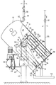
- annular chamber separator is shown in side view, partially in section.
- the ring chamber separator serves as an oil separator for removing oil from a cooling emulsion. It has a cylindrical elongated container 10, which consists of an annular housing body 11, which is closed at the top by the top wall 12, which is fixedly and non-removable to the housing body 11, for example welded.
- the inlet 14 for the raw liquid is located on the housing body 11 approximately halfway up. The inlet 14 leads tangentially into the container 10.
- the annular chambers 15-16 17 and 18 which surround the central chamber 19.
- the annular chambers 15-18 and the central chamber 19 are separated from one another by annular walls 20, 21, 22, 23 Cut.
- the outer ring wall 20, which surrounds the other ring walls forms with the upper wall 24 a bell open at the bottom. This bell forms, together with the ring walls 21, 22, 23 contained in it, a unit 25 as an independently manageable assembly.
- the outer ring wall 20 of the unit 25 and the ring wall 22 are fixedly connected to the upper wall 24. These ring walls do not extend to the bottom 26, which closes the lower opening of the container 10, but end at a distance from this bottom and, together with the bottom, form annular lower passages 27.
- the outer annular chamber 15 lying outside the unit 25 is delimited to the outside by the container body 11.
- the container 10 is sealed against the environment in a liquid-tight manner.
- the raw liquid flows from the inlet 14 tangentially into the outer annular chamber 15, in which it circulates. A portion of the light fraction rises in the annular chamber 15 and enters the head space 29 of the container 10 located above the unit 25.
- the remaining raw liquid flows through the outer passage 27 and rises in the annular chamber 16 and enters via the upper passage 28 the ring chamber 17. That part of the light fraction which is in the ring chambers 16 and 17 floats, rises into a pipe socket 30 extending from the passage 28.
- the remaining part of the raw liquid passes through the inner lower passage 27 into the annular chamber 18 and from there through the inner upper passage 28 into the central chamber 19.
- the upper end of the central chamber 19 is provided with a further connection piece 31, which is also in the head space 29 leads in.
- the head space 29 is connected via a pipe coupling 32 which can be pivoted about a horizontal axis to a riser pipe 33 into which the light fraction rises.
- the riser pipe has a height-adjustable overflow at a predetermined height, from which the liquid can be drained.
- the lower end of the central chamber 19 is also connected via a pipe coupling 34 which can be pivoted about a horizontal axis to an external riser pipe 35 into which the heavy fraction rises.
- the riser pipe 35 is also provided with an overflow.
- the difference in height of the overflows of the two risers 33 and 35 indicates the height at which the boundary layer between the heavy and light fractions is established inside the container 10.
- the riser pipe 33 contains a shut-off valve 36 and the riser pipe 35 contains a shut-off valve 37.
- the container base 26 can be opened around a hinge 38 relative to the container 10, so that the lower container opening is opened and the insert 25 can be pulled out of the container.
- the insert 25 has outwardly projecting spacers 39 which bridge the outer annular chamber 15 and center the insert in the interior of the container.
- the ring wall 21 which extends to the bottom 26 is centered in the interior of the ring wall 20 via spacers 39a and the inner ring wall 23 is centered in the interior via the spacers 39b Ring wall 22 centered.
- the spacers 39a and 39b can also rigidly connect the respectively adjacent ring walls to one another. In this case, the ring walls 20 and 22 connected to the top wall 24 carry the ring walls 21 and 23 not connected to the top wall.
- spacers 39, 39a and 39b in such a way that they adjoin the adjacent ring walls only at a mutual distance hold, but allow axial displacements of these ring walls relative to each other.
- the lower passages 27 can be bridged by singular support feet, via which the ring walls 20 and 22 rest on the floor 26.
- the ring wall 20 is fastened to the container wall 11 by detachable screw connection 56 in order to prevent the unit 25 from slipping out when the lid 26 is opened.
- the container 10 is mounted between two columns 40 so that it can be pivoted about a horizontal axis 41.
- support elements 42 in the form of stub axles are attached to the container in the central region of the container height and are mounted in a bearing device 43 of the columns 40.
- An adjusting device 44 serves to set and fix the respective angle of inclination of the container 10.
- the adjusting device allows the inclination of the container to be changed, for example, in angular steps of 15 °, the container being able to be adjusted between a position with a vertical container axis and a position with a horizontal container axis.
- the risers 33 and 35 are adjusted by pivoting around the pipe couplings 32 and 34 so that they each have a vertical orientation.
- the inlet 14 of the container 10 is connected via a flexible hose 45 to a pump 46 which is mounted on a bracket 47 which is attached to one of the columns 40.
- the pump 46 conveys the raw liquid with pressure into the container 10.
- the sludge outlet 48 is arranged in the region of the outer annular passage 27 at a point which is at the bottom when the container 10 is inclined and thus forms the deepest part of the interior of the container.
- the sludge outlet 49 is arranged in the interior of the central chamber 19 at a point which forms the lowest point of the central chamber when the container is inclined. Solids collect at the sludge outlet 48 and sink into the annular chambers 15 and 16. Solids collect at sludge outlet 49 and sink into central chamber 19. Experience has shown that hardly any solids are deposited in the annular chambers 17 and 18. If necessary, an outlet may also be provided on the inner lower passage 27.
- Valves 50 and 51 are normally shut off. These valves can be opened to drain the sludge deposited in the sludge outlets 48 and 49. As a result, the container contents run out into the discharge line 52 and the sludge is rinsed out of the sludge outlets. It is also possible, for the purpose of flushing, to shut off the valves 36 and 37 in the risers and to pressurize liquid into the Introduce inlet 14 so that the pressure from the opened valves 50 and 51 flushes out the sludge.
- the discharge line 52 leads, for example, to a paper band filter which retains the sludge, the dropping emulsion being able to be reused.
- the annular chamber separator can first be operated with the container 10 oriented vertically. It can then be tilted when one of the passages 27 has become clogged with mud. Due to the inclined position, at least the part of this passage 27 which is then at the top is cleared of sludge, since the sludge sinks to the lower tip of the container. It is also possible to change the degree of inclination depending on the slope angle of the sludge accumulation or to operate the deoiler at an angle from the outset.
- the annular chamber separator can also be provided with a bottom 26 which has no sludge outlet. In this case, occasional cleaning is required, for which purpose the tensioning device 53 holding the base 26 is released, so that the base can be folded up around the joint 38.
- the bottom is expediently opened after the container 10 has previously been pivoted into an almost horizontal position. In this state, the insert 25 can also be pulled horizontally out of the container.
Landscapes
- Chemical & Material Sciences (AREA)
- Chemical Kinetics & Catalysis (AREA)
- Physics & Mathematics (AREA)
- Thermal Sciences (AREA)
- Centrifugal Separators (AREA)
- Treatment Of Sludge (AREA)
- Refuse Collection And Transfer (AREA)
- Pens And Brushes (AREA)
- Eye Examination Apparatus (AREA)
- Surgical Instruments (AREA)
- Supply Devices, Intensifiers, Converters, And Telemotors (AREA)
Applications Claiming Priority (2)
| Application Number | Priority Date | Filing Date | Title |
|---|---|---|---|
| DE4102776A DE4102776A1 (de) | 1991-01-31 | 1991-01-31 | Ringkammerabscheider |
| DE4102776 | 1991-01-31 |
Publications (3)
| Publication Number | Publication Date |
|---|---|
| EP0497294A2 true EP0497294A2 (fr) | 1992-08-05 |
| EP0497294A3 EP0497294A3 (en) | 1992-09-23 |
| EP0497294B1 EP0497294B1 (fr) | 1995-05-10 |
Family
ID=6424021
Family Applications (1)
| Application Number | Title | Priority Date | Filing Date |
|---|---|---|---|
| EP92101402A Expired - Lifetime EP0497294B1 (fr) | 1991-01-31 | 1992-01-29 | Séparateur à chambre toroidal |
Country Status (3)
| Country | Link |
|---|---|
| EP (1) | EP0497294B1 (fr) |
| AT (1) | ATE122249T1 (fr) |
| DE (2) | DE4102776A1 (fr) |
Family Cites Families (8)
| Publication number | Priority date | Publication date | Assignee | Title |
|---|---|---|---|---|
| BE465066A (fr) * | 1945-07-31 | |||
| DE2540264B2 (de) * | 1975-09-10 | 1980-02-14 | Fritz 3096 Thedinghausen Schroeder | Vorrichtung zum Trennen zweier Flüssigkeiten |
| SE437122B (sv) * | 1979-11-20 | 1985-02-11 | Nordstjernan Rederi Ab | Forfarande och anordning for fordelning och tillforsel av suspension till en lamellsedimenteringsapparats sedimenteringsutrymmen |
| CS231773B1 (en) * | 1982-05-07 | 1984-12-14 | Miroslav Zajdlik | Device for curl separation of liquids with different density with automatic displacement |
| FR2536739B1 (fr) * | 1982-11-26 | 1986-01-03 | Chaudrofrance Sa | Separateur horizontal |
| DE8809056U1 (de) * | 1988-07-14 | 1988-10-06 | Schröder, Heinrich, Dipl.-Ing., 2819 Thedinghausen | Ringkammer-Abscheider |
| DE3929044A1 (de) * | 1989-09-01 | 1991-03-14 | Stephan Dipl Ing Winkelhorst | Oelabscheider |
| DE9002726U1 (de) * | 1990-03-08 | 1990-05-10 | Winkelhorst Trenntechnik GmbH, 5000 Köln | Ringkammer-Abscheider |
-
1991
- 1991-01-31 DE DE4102776A patent/DE4102776A1/de not_active Withdrawn
-
1992
- 1992-01-29 DE DE59202102T patent/DE59202102D1/de not_active Expired - Fee Related
- 1992-01-29 AT AT92101402T patent/ATE122249T1/de not_active IP Right Cessation
- 1992-01-29 EP EP92101402A patent/EP0497294B1/fr not_active Expired - Lifetime
Also Published As
| Publication number | Publication date |
|---|---|
| EP0497294A3 (en) | 1992-09-23 |
| DE4102776A1 (de) | 1992-08-06 |
| DE59202102D1 (de) | 1995-06-14 |
| EP0497294B1 (fr) | 1995-05-10 |
| ATE122249T1 (de) | 1995-05-15 |
Similar Documents
| Publication | Publication Date | Title |
|---|---|---|
| DE69534021T2 (de) | Auffangbehälter | |
| EP3222357B2 (fr) | Separateur de boue | |
| DE202008012099U1 (de) | Verbesserter Schmutzwassereinlauf | |
| EP0722760B1 (fr) | Filtre à arêtes pour liquides | |
| EP2319996A2 (fr) | Installation d'un filtre pour une bouche d'égout | |
| DE3626484C2 (fr) | ||
| EP0824947B1 (fr) | Séparateur de liquides et dispositif de séparation incorporable dans celui-ci | |
| EP0497294B1 (fr) | Séparateur à chambre toroidal | |
| EP2937127B1 (fr) | Dispositif de traitement de l'eau de pluie | |
| EP0657195A1 (fr) | Séparateur des boues et d'huile | |
| EP0497295A2 (fr) | Séparateur de liquide | |
| EP0445576A2 (fr) | Séparateur à chambre toroidale | |
| EP2957683B1 (fr) | Système de traitement d'eaux usées | |
| EP1270055B1 (fr) | Séparateur de boues et d'huile pour eaux usées | |
| DE19521741C2 (de) | Durchlaufabscheider mit zwei Stufen zum Abtrennen von Feststoffteilchen aus einer strömenden Flüssigkeit | |
| DE10348520B4 (de) | Filter für mit Metall-Ionen beladene Wässer | |
| DE19612775C2 (de) | Flüssigkeitsabscheider mit Koaleszenzfilter | |
| EP0768436B1 (fr) | Dispositif à extraire des substances solides de liquides, en particulier bouche d'égout, kit de montage et couvercle pour sa fabrication et tuyau de chasse et d'aspirateur d'entretien | |
| DE19847655A1 (de) | Zisternenfilter | |
| DE4241178C2 (de) | Schwimmstoff-Abscheider | |
| DE102004036029A1 (de) | Ölfilteranordnung und Mittelrohr | |
| DE4243171C1 (de) | Sandfang | |
| EP4239137A1 (fr) | Cage d'étranglement | |
| EP4461894A1 (fr) | Récipient de vidange, système et procédé de drainage de surface | |
| WO2023175005A1 (fr) | Appareil de séparation, dispositif d'alimentation, et procédé de purification d'un liquide |
Legal Events
| Date | Code | Title | Description |
|---|---|---|---|
| PUAI | Public reference made under article 153(3) epc to a published international application that has entered the european phase |
Free format text: ORIGINAL CODE: 0009012 |
|
| AK | Designated contracting states |
Kind code of ref document: A2 Designated state(s): AT BE CH DE FR GB IT LI NL SE |
|
| PUAL | Search report despatched |
Free format text: ORIGINAL CODE: 0009013 |
|
| AK | Designated contracting states |
Kind code of ref document: A3 Designated state(s): AT BE CH DE FR GB IT LI NL SE |
|
| 17P | Request for examination filed |
Effective date: 19930322 |
|
| 17Q | First examination report despatched |
Effective date: 19930624 |
|
| GRAA | (expected) grant |
Free format text: ORIGINAL CODE: 0009210 |
|
| AK | Designated contracting states |
Kind code of ref document: B1 Designated state(s): AT BE CH DE FR GB IT LI NL SE |
|
| PG25 | Lapsed in a contracting state [announced via postgrant information from national office to epo] |
Ref country code: IT Free format text: LAPSE BECAUSE OF FAILURE TO SUBMIT A TRANSLATION OF THE DESCRIPTION OR TO PAY THE FEE WITHIN THE PRESCRIBED TIME-LIMIT;WARNING: LAPSES OF ITALIAN PATENTS WITH EFFECTIVE DATE BEFORE 2007 MAY HAVE OCCURRED AT ANY TIME BEFORE 2007. THE CORRECT EFFECTIVE DATE MAY BE DIFFERENT FROM THE ONE RECORDED. Effective date: 19950510 Ref country code: FR Effective date: 19950510 Ref country code: GB Effective date: 19950510 Ref country code: NL Free format text: LAPSE BECAUSE OF FAILURE TO SUBMIT A TRANSLATION OF THE DESCRIPTION OR TO PAY THE FEE WITHIN THE PRESCRIBED TIME-LIMIT Effective date: 19950510 Ref country code: BE Effective date: 19950510 |
|
| REF | Corresponds to: |
Ref document number: 122249 Country of ref document: AT Date of ref document: 19950515 Kind code of ref document: T |
|
| REF | Corresponds to: |
Ref document number: 59202102 Country of ref document: DE Date of ref document: 19950614 |
|
| PG25 | Lapsed in a contracting state [announced via postgrant information from national office to epo] |
Ref country code: SE Effective date: 19950810 |
|
| EN | Fr: translation not filed | ||
| NLV1 | Nl: lapsed or annulled due to failure to fulfill the requirements of art. 29p and 29m of the patents act | ||
| GBV | Gb: ep patent (uk) treated as always having been void in accordance with gb section 77(7)/1977 [no translation filed] |
Effective date: 19950510 |
|
| PG25 | Lapsed in a contracting state [announced via postgrant information from national office to epo] |
Ref country code: AT Effective date: 19960129 |
|
| PG25 | Lapsed in a contracting state [announced via postgrant information from national office to epo] |
Ref country code: LI Effective date: 19960131 Ref country code: CH Effective date: 19960131 |
|
| PLBE | No opposition filed within time limit |
Free format text: ORIGINAL CODE: 0009261 |
|
| STAA | Information on the status of an ep patent application or granted ep patent |
Free format text: STATUS: NO OPPOSITION FILED WITHIN TIME LIMIT |
|
| 26N | No opposition filed | ||
| REG | Reference to a national code |
Ref country code: CH Ref legal event code: PL |
|
| PGFP | Annual fee paid to national office [announced via postgrant information from national office to epo] |
Ref country code: DE Payment date: 19991228 Year of fee payment: 9 |
|
| PG25 | Lapsed in a contracting state [announced via postgrant information from national office to epo] |
Ref country code: DE Free format text: LAPSE BECAUSE OF NON-PAYMENT OF DUE FEES Effective date: 20011101 |