EP0497312A2 - Porte-outil pour machine-outils - Google Patents
Porte-outil pour machine-outils Download PDFInfo
- Publication number
- EP0497312A2 EP0497312A2 EP92101467A EP92101467A EP0497312A2 EP 0497312 A2 EP0497312 A2 EP 0497312A2 EP 92101467 A EP92101467 A EP 92101467A EP 92101467 A EP92101467 A EP 92101467A EP 0497312 A2 EP0497312 A2 EP 0497312A2
- Authority
- EP
- European Patent Office
- Prior art keywords
- toolholder
- displacement
- holder body
- support shaft
- detection
- Prior art date
- Legal status (The legal status is an assumption and is not a legal conclusion. Google has not performed a legal analysis and makes no representation as to the accuracy of the status listed.)
- Granted
Links
Images


Classifications
-
- B—PERFORMING OPERATIONS; TRANSPORTING
- B23—MACHINE TOOLS; METAL-WORKING NOT OTHERWISE PROVIDED FOR
- B23B—TURNING; BORING
- B23B29/00—Holders for non-rotary cutting tools; Boring bars or boring heads; Accessories for tool holders
-
- B—PERFORMING OPERATIONS; TRANSPORTING
- B23—MACHINE TOOLS; METAL-WORKING NOT OTHERWISE PROVIDED FOR
- B23Q—DETAILS, COMPONENTS, OR ACCESSORIES FOR MACHINE TOOLS, e.g. ARRANGEMENTS FOR COPYING OR CONTROLLING; MACHINE TOOLS IN GENERAL CHARACTERISED BY THE CONSTRUCTION OF PARTICULAR DETAILS OR COMPONENTS; COMBINATIONS OR ASSOCIATIONS OF METAL-WORKING MACHINES, NOT DIRECTED TO A PARTICULAR RESULT
- B23Q17/00—Arrangements for observing, indicating or measuring on machine tools
- B23Q17/09—Arrangements for observing, indicating or measuring on machine tools for indicating or measuring cutting pressure or for determining cutting-tool condition, e.g. cutting ability, load on tool
-
- B—PERFORMING OPERATIONS; TRANSPORTING
- B23—MACHINE TOOLS; METAL-WORKING NOT OTHERWISE PROVIDED FOR
- B23Q—DETAILS, COMPONENTS, OR ACCESSORIES FOR MACHINE TOOLS, e.g. ARRANGEMENTS FOR COPYING OR CONTROLLING; MACHINE TOOLS IN GENERAL CHARACTERISED BY THE CONSTRUCTION OF PARTICULAR DETAILS OR COMPONENTS; COMBINATIONS OR ASSOCIATIONS OF METAL-WORKING MACHINES, NOT DIRECTED TO A PARTICULAR RESULT
- B23Q11/00—Accessories fitted to machine tools for keeping tools or parts of the machine in good working condition or for cooling work; Safety devices specially combined with or arranged in, or specially adapted for use in connection with, machine tools
- B23Q11/04—Arrangements preventing overload of tools, e.g. restricting load
-
- G—PHYSICS
- G01—MEASURING; TESTING
- G01L—MEASURING FORCE, STRESS, TORQUE, WORK, MECHANICAL POWER, MECHANICAL EFFICIENCY, OR FLUID PRESSURE
- G01L5/00—Apparatus for, or methods of, measuring force, work, mechanical power, or torque, specially adapted for specific purposes
- G01L5/12—Apparatus for, or methods of, measuring force, work, mechanical power, or torque, specially adapted for specific purposes for measuring axial thrust in a rotary shaft, e.g. of propulsion plants
-
- Y—GENERAL TAGGING OF NEW TECHNOLOGICAL DEVELOPMENTS; GENERAL TAGGING OF CROSS-SECTIONAL TECHNOLOGIES SPANNING OVER SEVERAL SECTIONS OF THE IPC; TECHNICAL SUBJECTS COVERED BY FORMER USPC CROSS-REFERENCE ART COLLECTIONS [XRACs] AND DIGESTS
- Y10—TECHNICAL SUBJECTS COVERED BY FORMER USPC
- Y10T—TECHNICAL SUBJECTS COVERED BY FORMER US CLASSIFICATION
- Y10T408/00—Cutting by use of rotating axially moving tool
- Y10T408/13—Cutting by use of rotating axially moving tool with randomly-actuated stopping means
- Y10T408/14—Responsive to condition of Tool or tool-drive
Definitions
- the present invention relates to a toolholder device for machine tools and, more particularly, to a toolholder device capable of detecting overload thrust applied to the tool, such as a drill or tap, for preventing damage of the tool.
- a drive toolholder or holder body driven by the drive spindle has a driven toolholder supported by the holder body in a manner to be rotatable and axially shiftable relative to the holder body.
- the driven toolholder is urged forwardly by a thrust setting spring.
- the drive holder body and the driven toolholder have their respective displacement detecting elements or teeth disposed circumferentially thereof in interdigitating relationship. Circumferentially adjacent displacement detecting teeth of the drive side and the driven side are brought into abutment with each other by means of a torsion coil spring connecting the driven toolholder with the drive holder body.
- These displacement detecting teeth of the drive and driven sides have mutually engaging beveled surfaces at their mutually abutting sides.
- the beveled surfaces make a relatively small angle to the axial direction of the toolholder.
- the object of the present invention is to solve the above problem and to provide a toolholder device for a machine tool capable of lessening the influence on the depth of a hole to be cut, under overload thrust condition, by making the amount of axial displacement of the toolholder as small as possible.
- a toolholder device for a machine tool of the type having a drive spindle for imparting rotation to a cutting tool
- said toolholder device comprising: a holder body to be coaxially coupled to the drive spindle for joint rotation therewith; a driven toolholder coupled to the holder body so as to be rotatable coaxially with the holder body and to be movable axially relative to the holder body, said toolholder having means for coaxially holding the cutting tool; spring means disposed between the holder body and the driven toolholder for yielding axially to cause the toolholder to axially displace relative to the holder body only when an axial thrust force exceeding a set value is applied to the cutting tool; a set of displacement detecting elements provided on the holder body at circumferential spacings about an axis of the holder body and the toolholder; a set of displacement detecting elements provided on the toolholder at circumferential spacings about said axis and arranged interdigitatingly with the displacement detecting elements of
- the displacement translation means is placed radially inwardly of the displacement detecting elements so that translated circumferential displacement of the toolholder is multiplied at the displacement detecting elements located radially outwardly of the translating means and the multiplied circumferential displacement can be reliably detected.
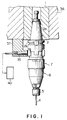
- FIGS. 1 and 2 show a toolholder device 7 for machine tools in accordance with a first embodiment of the present invention.
- the toolholder device 7 comprises a holder body 2 detachably secured to a drive spindle 1 of a machine tool, and a driven toolholder 6 having at its distal end a collect chuck 5 for gripping a cutting tool 4.
- the holder body 2 includes a tapered portion 2a, a grip portion 2b integrally formed with the tapered portion 2a, and a support shaft 3 extending forward or downward (as viewed) centrally from the grip portion 2b.
- the support shaft 3 extends into the driven toolholder 6 which includes a holding tube 9, a connection tube 10 integrally screwed onto the periphery of the holding tube 9, and a support tube 11 fixedly secured in a hollow defined by the tubes 9 and 10.
- a support hole 11a formed within the support cylinder 11 and the outer surface of the support shaft 3 are provided with sloping guide grooves or lead grooves 12 confronting each other and helically extending about the rotational axis of the toolholder device 7.
- a circulation passage 15 is provided within the support tube 11 for circulating the balls 13.
- the displacement translation mechanism 14 formed within the toolholder device 7 is a ball thread structure in which the balls are in rolling contact with the support shaft 3 and the support cylinder 11 to reduce the frictional force.
- the lead angle of the screw threads is approximately 9 degrees.
- a torsion coil spring 16 for transmitting the torque has one end 16a linked with the connection tube 10 of the driven toolholder 6, and the other end 16b linked with the grip portion 2b of the holder body 2, to thereby transmit the rotational movement of the holder body 2 to the driven toolholder 6 during the machining operation.
- a detection ring 19 has fixed thereto a couple of diametrically oppositely arranged engagement pins 18 which are engaged with or disengaged from a multiplicity of engaging holes 17 provided in the connection tube 10 as shown in FIG. 3.
- the detection ring 19 is downwardly (as viewed) urged by a spring 20 intervening between the detection ring 19 and the grip portion 2b whereby the detection ring 19 is secured to the connection tube 10.
- the detection ring 19 is moved backward (upward in FIG. 2) against the action of the spring 20 for disengagement of the pins 18 from the engaging holes 17, and then the connection tube 10 is circumferentially turned to again engage the pins 18 with other engaging holes 17 of the detection ring 19.
- the torsional force of the torsion coil spring 16 is determined to be smaller than a smaller one of the maximum allowable thrust load and the maximum allowable torque, so as to be able to cope with both the thrust load and the torque to be applied to the tool 4.
- each of the displacement detecting elements 21 has two detection portions 22 and 23 which are located on two sides of each element 21 with respect to the rotational direction of the toolholder device. These detection portions function for the initiation or completion of the detection by means of a proximity switch 35 described later.
- the proximity switch 35 senses the detection spacing 29 and is again turned off, the spindle angular pulse P s is subtracted from the pulse count value which is the result of the addition in the preceding step. Then the proximity switch 35 senses the displacement detecting element 21 and is turned on so that the judgment command signal is output to compare the count value with the set value t .
- one side of each displacement detecting element 21 is in contact with the one side 30a of each shoulder 30 of the reference detecting element 24 owing to the force of the torsion coil spring 16 and the conversion mechanism 14, and hence the detection spacings 28 and 29 are maintained to have the same dimension L .
- the count value within the counter 45 becomes zero, and the output signals for the excessive or overload torque are not generated.
- the ball screw mechanism acting as the translation mechanism has a small lead angle, the axial displacement is even diminished due to the gentle lead angle thereof. This lessens the influence of the axial retracting displacement of the toolholder 6 upon the depth of the hole. It should be noted that the same operation as described above will occur in the case where the tool is subjected to only excessive torque greater than the force of the torsional coil spring 16 or to simultaneous excessive torque and thrust load.
- the pair of guide grooves 12 constituting the displacement translation mechanism 14 of the toolholder 51 are in the form of lead grooves, but alternatively a plurality of cam grooves may be provided along the tracks of the lead grooves to constitute guide grooves as a whole.
- the toolholder device 55 comprises a holder body 2 including a holder tube 56, a support cylinder 11 and a bearing tube 58, and a toolholder 6 including a detection tube 59 integrally screwed around the lower periphery of a support shaft 3.
- the holder tube 56 includes a tapered portion 56a formed in the upper part thereof, a grip portion 56b integral with the tapered portion 56a, and a tubular portion 56c extending downwardly from the grip portion 56b.
- the support cylinder 11 is initially fitted into an insertion hole 60 of the tubular portion 56c, and then the outer periphery of the bearing tube 58 is integrally screwed into the insertion hole 60 from below to form the holder body 2.
- the top portion of the support shaft 3 of the toolholder 6 is fitted into a support hole 11a provided within the support cylinder 11.
- the support hole 11a and an upper peripheral portion of the support shaft 3 are correspondingly provided with guide grooves 12 in the same manner as in the first embodiment.
- Balls 13 are interposed between the guide grooves 12 for the formation of the displacement translation mechanism 14.
- a ball bearing 52 is interposed between the bearing tube 58 and an intermediate outer peripheral portion of the support shaft 3.
- a central hole 62 opening into the insertion hole 60.
- the central hole 62 has at its bottom a shoulder 62a for abutting against a flange 63a of a cylindrical block 63 inserted into the central hole 23.
- the bottom end surface of the cylindrical block 63 and the top end surface of the support shaft 3 have recesses 63b and 3a, respectively which cooperate to receive a steel ball 66 therebetween.
- the cylindrical block 63 is downwardly forced by a thrust load setting spring 67 in the hole 62.
- a support mechanism 68 is thus configured.
- the rotational movement of the holder body 2 is transmitted to the toolholder 6.
- the compressive force of the spring 67 subjected to the excessive thrust load or torque caused in the tool can be adjusted by removing a pull stud 69 to replace the spring 67 with a spring having a different compressive force.
- a reference detecting element 24 integrally screwed around the outer periphery of the holder tube 56 constituting the holder body 2, and a displacement detecting element 21 provided on the outer periphery of the detecting tube 59 constituting the toolholder 6 are substantially the same in shape and configuration as those employed in the first embodiment.
- An overload detecting circuit 40 for detecting excessive torque (or thrust load) is equivalent to that in the first embodiment.
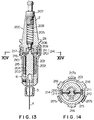
- a holder body 2 comprises a tapered portion 71 formed in the upper part thereof, a grip portion 73 integrated with the tapered portion 71, a support shaft 74 axially slidably inserted in the center of the tapered portion 71, and a thrust load setting spring 75 for biasing the support shaft 74 downwardly as viewed in FIG. 9.
- the spring 75 is subjected to thrust load imposed on the tool, such as a drill, held by the toolholder 6 and designed so as not to axially yield backward until it is surpassed by an axial thrust load of a predetermined setting value.
- the support shaft 74 has a front end surface 76 of conical shape, and a sleeve 77 is slidably fitted around the shaft 74.
- the sleeve 77 has a rear end surface 78 shaped into a conical surface.
- Relatively large- and small-diameter pivot ball bearings 79 and 80 for bearing the conical surfaces 76 and 78, respectively are fitted into a holding tube 81 of the toolholder 6.
- a spring retainer 82 mounted on the support shaft 74 so as not to be forwardly displaceable in the axial direction and a flange 77a of the sleeve 77, there is interposed a spring 83 whose spring force confers a pre-load to the pivot ball bearings by way of the two conical surfaces 76 and 78.
- the spring force is set to provide a pre-load which minimizes the frictional torque caused by the pivot ball bearings 79, 80.
- a collect chuck for holding the tool is attached to the front end of the holding tube 81. In place of the pivot ball bearings, deep groove ball bearings may be used.
- a connection tube 84 is integrally screwed on the periphery of the holding tube 81.
- a torsional coil spring 85 for torque transmission has one end connected to the connection tube 84 and the other end connected to the grip portion 73.
- the detection ring 88 is biased forwardly by a spring 89 interposed between the ring 88 and the grip portion 73. Accordingly, for adjustment of the torsional force of the coiled torsion spring 85, the detection ring 88 is first displaced upward against the spring force to disengage the engaging holes 87 from the engaging pins 86. Then the holding tube 81 and the connection tube 84 are circumferentially rotated before other engaging holes 87 of the detection ring 88 are engaged with the engaging pins 86.
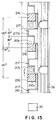
- the upper portion of the detection ring 88 is shaped to have relatively large and small diameter of tubular portions 90 and 91 which, as shown in FIG. 10, have a plurality of (three for each in FIG. 10) recesses 92 and 93, respectively.
- recesses 92 and 93 there are provided three displacement detection elements 94 and three displacement translation element 95 which are circumferentially equally angularly spaced (at intervals of angle ⁇ (120°) as shown in FIGS. 11 and 12).
- three reference detection elements 96 project from the grip portion 73 into the three recesses 92 of the large-diameter tubular portion 90, while as shown in FIG.
- three reference displacement translation elements 97 project from the grip portion 73 into the three recesses 92 of the small-diameter tubular portion 91.
- sides of the displacement detection elements 94 and the reference detection elements 96 in respect of the rotational direction serves for initiation and termination of the detection by a proximity switch 35 in the same manner as in the first embodiment.
- a pair of detection spacings 102 and 103 for rotational displacement are formed between a pair of the sides 99 and 100, and between the sides 98 and 101, respectively. Therefore, three pairs of detection spacing are provided along the circumference. Upon detecting these detection spacings 102 and 103, the proximity switch 35 is turned off.
- each reference displacement translation element 97 has at one side a sloping slant surface 105 designed to engage a slant surface 104 provided on one side of the displacement translation element 95.
- the slant surface 104 is brought into contact with the slant surface 105 by the torsional force of the torsional coil spring 85 to constitute a displacement translation mechanism by which axial movement of the toolholder 6 is converted into a circumferential rotational movement when the tool is subjected to excessive thrust load.
- the slant surfaces 104 and 105 are in contact with each other, there is a small circumferential clearances (designated by a in FIGS.
- the pair of detection spacings 102 and 103, the reference detection element 96, the displacement detection element 94, and displacement translation element 95 all have the same circumferential dimension L (30 degrees) while the recesses 92 and 93 of the relatively large- and small-diameter tubular portion 90 and 91, respectively, and the reference translation element 97 all have the same circumferential dimension 3 L (90 degrees).
- an overload detection circuit 40 for detecting excessive thrust load (or excessive torque) is equivalent to that employed in the first embodiment.
- the displacement detection elements 94 provided on the periphery of the toolholder device 70 are circumferentially fully separated from the associated reference detection elements 96. Therefore, these elements 94 and 97 are prevented from contacting each other, contrary to the first embodiment where one side of the displacement detection element 21 abuts against one side of the reference detecting element 24 due to the circumferential rotational movement, of the predetermined amount (clearances a ), of the displacement detection element 21. For this reason, the relative circumferential movement between the detection elements 94 and 96 can be performed without suffering from the external influence by the machining liquid or dust.
- the steel ball 209 compresses the compression spring 208 through the pressure contact block 206 to retreat the toolholder 6, and the guide grooves 211 are guided by the guide pins 210 with the aid of the displacement translation mechanism 214 with the result that the displacement detection element 216 are rotated in the direction opposite to the direction Z while retreating. At that time, there occurs a slippage between the ball 209 and the pressure contact block 206. In this manner, the rotation of the displacement detection elements 216 changes the intervals between the detection portion 216c and 217c, so that the changed intervals are compared with the value (60° described above) taken in the normal state. If it is outside a preset allowable value, an overload signal is generated.
- the toolholder device of the present invention employs a displacement translation mechanism utilizing sloping surfaces arranged within the toolholder device, to multiply an axial displacement of the toolholder into a circumferential rotational movement. Therefore, the amount of axial displacement of the toolholder required to obtain a predetermined amount of angular movement for detecting at least excessive thrust load, can be reduced. Accordingly, in a case of a toolholder device where the toolholder is axially moved for the detection of a thrust load, the influence of the axial displacement on the depth of machined hole can be diminished.
Landscapes
- Engineering & Computer Science (AREA)
- Mechanical Engineering (AREA)
- Chemical & Material Sciences (AREA)
- Combustion & Propulsion (AREA)
- Physics & Mathematics (AREA)
- General Physics & Mathematics (AREA)
- Machine Tool Sensing Apparatuses (AREA)
- Gripping On Spindles (AREA)
- Automatic Tool Replacement In Machine Tools (AREA)
- Force Measurement Appropriate To Specific Purposes (AREA)
- Details Of Cutting Devices (AREA)
Applications Claiming Priority (2)
| Application Number | Priority Date | Filing Date | Title |
|---|---|---|---|
| JP3189391 | 1991-01-30 | ||
| JP31893/91 | 1991-01-30 |
Publications (3)
| Publication Number | Publication Date |
|---|---|
| EP0497312A2 true EP0497312A2 (fr) | 1992-08-05 |
| EP0497312A3 EP0497312A3 (en) | 1992-12-02 |
| EP0497312B1 EP0497312B1 (fr) | 1994-07-06 |
Family
ID=12343701
Family Applications (1)
| Application Number | Title | Priority Date | Filing Date |
|---|---|---|---|
| EP92101467A Expired - Lifetime EP0497312B1 (fr) | 1991-01-30 | 1992-01-29 | Porte-outil pour machine-outils |
Country Status (5)
| Country | Link |
|---|---|
| US (1) | US5351039A (fr) |
| EP (1) | EP0497312B1 (fr) |
| KR (1) | KR950004664B1 (fr) |
| DE (1) | DE69200217T2 (fr) |
| TW (1) | TW201713B (fr) |
Cited By (3)
| Publication number | Priority date | Publication date | Assignee | Title |
|---|---|---|---|---|
| JP2017140688A (ja) * | 2016-02-12 | 2017-08-17 | エヌティーツール株式会社 | スマートツールホルダ |
| CN107553216A (zh) * | 2017-09-06 | 2018-01-09 | 天津大学 | 偏心可调测试球和测试系统及机床主轴回转精度检测方法 |
| CN115560975A (zh) * | 2022-11-09 | 2023-01-03 | 山东海鲲数控设备有限公司 | 一种数控机床弹性卡盘的可靠性试验设备 |
Families Citing this family (22)
| Publication number | Priority date | Publication date | Assignee | Title |
|---|---|---|---|---|
| US5876158A (en) * | 1997-12-03 | 1999-03-02 | Beiter; Russell R. | Drive collet assembly for a tap with overdrive protection |
| KR20020072883A (ko) * | 2001-03-13 | 2002-09-19 | 이상문 | 공구홀더 |
| KR100601897B1 (ko) | 2004-04-16 | 2006-07-19 | 삼성광주전자 주식회사 | 사이클론 집진장치 및 이를 이용한 진공청소기 |
| JP4799045B2 (ja) * | 2005-05-17 | 2011-10-19 | 株式会社東京精密 | 工作機械 |
| US20090065225A1 (en) * | 2007-09-07 | 2009-03-12 | Black & Decker Inc. | Switchable anti-lock control |
| US7717191B2 (en) | 2007-11-21 | 2010-05-18 | Black & Decker Inc. | Multi-mode hammer drill with shift lock |
| US7798245B2 (en) | 2007-11-21 | 2010-09-21 | Black & Decker Inc. | Multi-mode drill with an electronic switching arrangement |
| US7762349B2 (en) | 2007-11-21 | 2010-07-27 | Black & Decker Inc. | Multi-speed drill and transmission with low gear only clutch |
| US7770660B2 (en) | 2007-11-21 | 2010-08-10 | Black & Decker Inc. | Mid-handle drill construction and assembly process |
| US7735575B2 (en) | 2007-11-21 | 2010-06-15 | Black & Decker Inc. | Hammer drill with hard hammer support structure |
| US7854274B2 (en) | 2007-11-21 | 2010-12-21 | Black & Decker Inc. | Multi-mode drill and transmission sub-assembly including a gear case cover supporting biasing |
| US7717192B2 (en) | 2007-11-21 | 2010-05-18 | Black & Decker Inc. | Multi-mode drill with mode collar |
| US8393231B2 (en) * | 2010-11-15 | 2013-03-12 | Legend Lifestyle Products Corp. | Multifunctional torque tool detection device |
| TWI422462B (zh) * | 2011-07-11 | 2014-01-11 | Hsin Yu Cheng | 具感測器之動力刀把構造 |
| US8925169B2 (en) * | 2011-09-21 | 2015-01-06 | The Boeing Company | Drill force indicator for hand-operated drills |
| CN103056700B (zh) * | 2011-10-24 | 2015-06-03 | 鸿富锦精密工业(深圳)有限公司 | 刀座 |
| DE102014100124A1 (de) * | 2014-01-08 | 2015-07-09 | Claas Selbstfahrende Erntemaschinen Gmbh | Vorrichtung zur Erfassung des Zustands eines Maschinenelements |
| CN109940202B (zh) * | 2019-04-15 | 2024-05-07 | 德州德隆(集团)机床有限责任公司 | 一种枪钻加工用过载保护装置及其装配方法 |
| CN111570884B (zh) * | 2020-06-08 | 2024-09-27 | 齐重数控装备股份有限公司 | 车铣刀架旋转错位拉刀机构 |
| CN112720064B (zh) * | 2021-01-04 | 2022-07-08 | 吉林大学 | 一种基于可靠性设计的数控机床主轴夹刀检测装置 |
| CN113118512B (zh) * | 2021-04-14 | 2022-05-17 | 上汽大众汽车有限公司 | 一种具有切削抗力过载自动保护的孔加工刀柄 |
| DE102023207076A1 (de) * | 2023-07-25 | 2025-01-30 | Robert Bosch Gesellschaft mit beschränkter Haftung | Anpresskraftanzeigevorrichtung mit einer Werkzeugaufnahme |
Family Cites Families (9)
| Publication number | Priority date | Publication date | Assignee | Title |
|---|---|---|---|---|
| US3387669A (en) * | 1966-01-20 | 1968-06-11 | Ingersoll Rand Co | Impact wrench torque-measuring device |
| US3652099A (en) * | 1970-02-19 | 1972-03-28 | Otto Bilz | Drill chuck |
| US3851525A (en) * | 1972-10-13 | 1974-12-03 | J Parkinson | Thrust-meter utilizing a phase measurement system for thurst measurement |
| US4193720A (en) * | 1977-08-15 | 1980-03-18 | Kenji Machida | Critical torque detector |
| EP0038886A1 (fr) * | 1980-04-28 | 1981-11-04 | Kenji Machida | Détecteur d'un couple critique |
| US4488443A (en) * | 1983-01-20 | 1984-12-18 | Simmonds Precision Products, Inc. | Expanded range monopole torque measuring system |
| GB2208716B (en) * | 1987-08-12 | 1991-02-27 | Smiths Industries Plc | Speed and torque sensors |
| DD269816A1 (de) * | 1987-12-30 | 1989-07-12 | Chemieanlagenbaukombinat Bt Ch | Verfahren und vorrichtung zur sicherung von bohr- und gewindeschneidwerkzeugen |
| JPH0741519B2 (ja) * | 1990-02-20 | 1995-05-10 | 豊和工業株式会社 | 過負荷トルク検出装置 |
-
1992
- 1992-01-28 TW TW081100671A patent/TW201713B/zh active
- 1992-01-28 US US07/827,227 patent/US5351039A/en not_active Expired - Fee Related
- 1992-01-29 DE DE69200217T patent/DE69200217T2/de not_active Expired - Fee Related
- 1992-01-29 EP EP92101467A patent/EP0497312B1/fr not_active Expired - Lifetime
- 1992-01-30 KR KR1019920001395A patent/KR950004664B1/ko not_active Expired - Fee Related
Cited By (4)
| Publication number | Priority date | Publication date | Assignee | Title |
|---|---|---|---|---|
| JP2017140688A (ja) * | 2016-02-12 | 2017-08-17 | エヌティーツール株式会社 | スマートツールホルダ |
| CN107553216A (zh) * | 2017-09-06 | 2018-01-09 | 天津大学 | 偏心可调测试球和测试系统及机床主轴回转精度检测方法 |
| CN115560975A (zh) * | 2022-11-09 | 2023-01-03 | 山东海鲲数控设备有限公司 | 一种数控机床弹性卡盘的可靠性试验设备 |
| CN115560975B (zh) * | 2022-11-09 | 2023-03-21 | 山东海鲲数控设备有限公司 | 一种数控机床弹性卡盘的可靠性试验设备 |
Also Published As
| Publication number | Publication date |
|---|---|
| KR950004664B1 (ko) | 1995-05-04 |
| EP0497312B1 (fr) | 1994-07-06 |
| EP0497312A3 (en) | 1992-12-02 |
| TW201713B (fr) | 1993-03-11 |
| DE69200217T2 (de) | 1994-10-27 |
| DE69200217D1 (de) | 1994-08-11 |
| US5351039A (en) | 1994-09-27 |
| KR920014547A (ko) | 1992-08-25 |
Similar Documents
| Publication | Publication Date | Title |
|---|---|---|
| EP0497312B1 (fr) | Porte-outil pour machine-outils | |
| US4305597A (en) | Keyless self-tightening chuck | |
| US4386689A (en) | Torque limiter | |
| US4836563A (en) | Selftightening drill chuck | |
| US4123074A (en) | Tool shank and chuck combination for a hammer drill | |
| US5855377A (en) | Dead length collect chuck assembly | |
| US5131255A (en) | Power driven tool | |
| KR930011854B1 (ko) | 공구의 과부하 검출장치 | |
| US4991860A (en) | Drill chuck | |
| US5076740A (en) | Toolholders for machine tools | |
| US4991859A (en) | Self-tightening drill chuck | |
| JPS63139603A (ja) | ドリルチャック | |
| JPS6047047B2 (ja) | タツプホルダ | |
| JPH0358845B2 (fr) | ||
| CA1152778A (fr) | Porte-taraud | |
| US4317511A (en) | Overload release clutch | |
| EP3406397B1 (fr) | Système de mandrinage à entraînement électrique comprenant un système d'embrayage automatique | |
| US4507031A (en) | Power chuck for turning machines | |
| US5037254A (en) | Tool clamping device | |
| US2127855A (en) | Power-operated tool | |
| US2843388A (en) | Self-tightening reversible chuck | |
| JPH0796181B2 (ja) | 工具ホルダ | |
| GB2199776A (en) | Self tightening drill chuck | |
| EP0051097A1 (fr) | Limiteur de couple | |
| US4602799A (en) | Hammer-drill chuck |
Legal Events
| Date | Code | Title | Description |
|---|---|---|---|
| PUAI | Public reference made under article 153(3) epc to a published international application that has entered the european phase |
Free format text: ORIGINAL CODE: 0009012 |
|
| AK | Designated contracting states |
Kind code of ref document: A2 Designated state(s): CH DE FR GB IT LI |
|
| PUAL | Search report despatched |
Free format text: ORIGINAL CODE: 0009013 |
|
| AK | Designated contracting states |
Kind code of ref document: A3 Designated state(s): CH DE FR GB IT LI |
|
| 17P | Request for examination filed |
Effective date: 19930419 |
|
| 17Q | First examination report despatched |
Effective date: 19931102 |
|
| GRAA | (expected) grant |
Free format text: ORIGINAL CODE: 0009210 |
|
| AK | Designated contracting states |
Kind code of ref document: B1 Designated state(s): CH DE FR GB IT LI |
|
| REF | Corresponds to: |
Ref document number: 69200217 Country of ref document: DE Date of ref document: 19940811 |
|
| ET | Fr: translation filed | ||
| ITF | It: translation for a ep patent filed | ||
| PLBE | No opposition filed within time limit |
Free format text: ORIGINAL CODE: 0009261 |
|
| STAA | Information on the status of an ep patent application or granted ep patent |
Free format text: STATUS: NO OPPOSITION FILED WITHIN TIME LIMIT |
|
| 26N | No opposition filed | ||
| PGFP | Annual fee paid to national office [announced via postgrant information from national office to epo] |
Ref country code: FR Payment date: 20011228 Year of fee payment: 11 |
|
| REG | Reference to a national code |
Ref country code: GB Ref legal event code: IF02 |
|
| PGFP | Annual fee paid to national office [announced via postgrant information from national office to epo] |
Ref country code: GB Payment date: 20020130 Year of fee payment: 11 |
|
| PGFP | Annual fee paid to national office [announced via postgrant information from national office to epo] |
Ref country code: DE Payment date: 20020227 Year of fee payment: 11 |
|
| PGFP | Annual fee paid to national office [announced via postgrant information from national office to epo] |
Ref country code: CH Payment date: 20020426 Year of fee payment: 11 |
|
| PG25 | Lapsed in a contracting state [announced via postgrant information from national office to epo] |
Ref country code: GB Free format text: LAPSE BECAUSE OF NON-PAYMENT OF DUE FEES Effective date: 20030129 |
|
| PG25 | Lapsed in a contracting state [announced via postgrant information from national office to epo] |
Ref country code: LI Free format text: LAPSE BECAUSE OF NON-PAYMENT OF DUE FEES Effective date: 20030131 Ref country code: CH Free format text: LAPSE BECAUSE OF NON-PAYMENT OF DUE FEES Effective date: 20030131 |
|
| PG25 | Lapsed in a contracting state [announced via postgrant information from national office to epo] |
Ref country code: DE Free format text: LAPSE BECAUSE OF NON-PAYMENT OF DUE FEES Effective date: 20030801 |
|
| REG | Reference to a national code |
Ref country code: CH Ref legal event code: PL |
|
| GBPC | Gb: european patent ceased through non-payment of renewal fee | ||
| PG25 | Lapsed in a contracting state [announced via postgrant information from national office to epo] |
Ref country code: FR Free format text: LAPSE BECAUSE OF NON-PAYMENT OF DUE FEES Effective date: 20030930 |
|
| REG | Reference to a national code |
Ref country code: FR Ref legal event code: ST |
|
| PG25 | Lapsed in a contracting state [announced via postgrant information from national office to epo] |
Ref country code: IT Free format text: LAPSE BECAUSE OF NON-PAYMENT OF DUE FEES;WARNING: LAPSES OF ITALIAN PATENTS WITH EFFECTIVE DATE BEFORE 2007 MAY HAVE OCCURRED AT ANY TIME BEFORE 2007. THE CORRECT EFFECTIVE DATE MAY BE DIFFERENT FROM THE ONE RECORDED. Effective date: 20050129 |