EP0497364B1 - Optisches Radargerät für Fahrzeuge - Google Patents
Optisches Radargerät für Fahrzeuge Download PDFInfo
- Publication number
- EP0497364B1 EP0497364B1 EP92101613A EP92101613A EP0497364B1 EP 0497364 B1 EP0497364 B1 EP 0497364B1 EP 92101613 A EP92101613 A EP 92101613A EP 92101613 A EP92101613 A EP 92101613A EP 0497364 B1 EP0497364 B1 EP 0497364B1
- Authority
- EP
- European Patent Office
- Prior art keywords
- light
- light emitting
- optical
- light receiving
- lens
- Prior art date
- Legal status (The legal status is an assumption and is not a legal conclusion. Google has not performed a legal analysis and makes no representation as to the accuracy of the status listed.)
- Expired - Lifetime
Links
Images


Classifications
-
- G—PHYSICS
- G01—MEASURING; TESTING
- G01S—RADIO DIRECTION-FINDING; RADIO NAVIGATION; DETERMINING DISTANCE OR VELOCITY BY USE OF RADIO WAVES; LOCATING OR PRESENCE-DETECTING BY USE OF THE REFLECTION OR RERADIATION OF RADIO WAVES; ANALOGOUS ARRANGEMENTS USING OTHER WAVES
- G01S17/00—Systems using the reflection or reradiation of electromagnetic waves other than radio waves, e.g. lidar systems
- G01S17/88—Lidar systems specially adapted for specific applications
- G01S17/93—Lidar systems specially adapted for specific applications for anti-collision purposes
- G01S17/931—Lidar systems specially adapted for specific applications for anti-collision purposes of land vehicles
-
- G—PHYSICS
- G01—MEASURING; TESTING
- G01S—RADIO DIRECTION-FINDING; RADIO NAVIGATION; DETERMINING DISTANCE OR VELOCITY BY USE OF RADIO WAVES; LOCATING OR PRESENCE-DETECTING BY USE OF THE REFLECTION OR RERADIATION OF RADIO WAVES; ANALOGOUS ARRANGEMENTS USING OTHER WAVES
- G01S7/00—Details of systems according to groups G01S13/00, G01S15/00, G01S17/00
- G01S7/48—Details of systems according to groups G01S13/00, G01S15/00, G01S17/00 of systems according to group G01S17/00
- G01S7/481—Constructional features, e.g. arrangements of optical elements
- G01S7/4811—Constructional features, e.g. arrangements of optical elements common to transmitter and receiver
Definitions
- This invention relates to a vehicular optical-radar apparatus, and particularly to a vehicular optical-radar apparatus utilized for other optical radar apparatuses.
- a conventional optical distance-measuring apparatus As shown in Figs. 12 and 13, light emitted from a light emitting portion 1 arranged within a lens-barrel 5 transmits through a light emitting lens 3 and is then formed into an outgoing light Lt.
- the outgoing light Lt irradiates on a reflecting body, for example, a reflex reflector of an object of a distant vehicle ahead or the like and is formed into a reflecting light Lr, which is condensed by a light receiving lens 4 and received by a light receiving portion 2 of the lens-barrel 5.
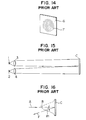
- a beam spot 7 reflected in a screen 6 irradiated on the object is substantially circular as shown in Fig. 14.
- the distance between the light emitting and receiving portions is D.
- the beam spot irradiated on the object is circular as shown in Fig. 14, and unnecessary portions are present in upper and lower ends or the like. Accordingly, as shown in Figs. 15 and 16, out of light irradiated on a reflecting body C, a portion in which an angle ⁇ 1 between an incident axis B and a reflecting light F is large, that is, a less effective power portion is utilized. This causes a problem in that detection performance of the light receiving portion is deteriorated.
- optical distance-measuring apparatus for use with vehicles is insufficient in reliability such as precision. Further improvements have been required.
- DE-A-3 616 930 discloses a distance measurement device in which light can be forwardly irradiated and the reflected light can be received.
- a plurality of lenses are provided the optical axles of which are arranged at certain angles with respect to each other. The light reflected from the individual light beams is used for the purpose of selective identification of an object.
- DE-A-3 106 539 describes an optical imaging apparatus comprising a series of lenses having a deformed shape so as to allow a close arrangement and a small image angle and to allow combination with a prism.
- the close arrangement of a larger plurality of lenses in a certain area allows obtaining a sufficient amount of light.
- a light emitting portion (a light emitting element) passes through a light emitting lens and is formed into an outgoing light. At that time, a beam spot irradiated on a distant object, for example, a vehicle ahead is formed into a substantially laterally lengthy elliptical shape as shown in Fig. 4.
- the irradiated light is reflected in a reflex reflector at the rear of an object and formed into a reflecting light, which is condensed by a light receiving lens and received by a light receiving portion (a light receiving element).
- a box may be fixed so that it is horizontal while watching a level, and a unit is assembled so that a beam irradiating angle and a beam receiving angle are horizontal.
- an optical axis of a distance measuring system Prior to mounting the apparatus on the vehicle, an optical axis of a distance measuring system is adjusted using a level.
- the vehicle When the apparatus is mounted on the vehicle after the unit has been assembled, the vehicle is arranged horizontally and mounted so that the unit is horizontal while watching the level.
- the level When the assembly of the unit and the mounting to the vehicle are completed in accordance with the aforementioned procedure, the level may be removed for re-use for other units or the level may remain mounted for use at the time of checking such as inspection.
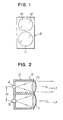
- a vehicular optical radar apparatus R comprises a light emitting portion 8 for irradiating a signal light on an object ahead and a light receiving portion 9 for receiving reflecting light from said object.
- An optical system mount 12 has the light emitting portion (light emitting element) 8 and the light receiving portion (light receiving element) 9 which are arranged in separate chambers.
- a light emitting lens 10 is arranged on the side of the light emitting portion 8, and a light receiving lens 11 is arranged on the side of the light receiving portion 9.
- Figs. 1 and 2 show a first embodiment of the present invention.
- the light emitting lens 10 is deformation-worked with upper and lower ends E cut off as shown in Fig. 3 so that the distance DI between optical centers of both the light emitting and receiving portions 8 and 9 can be moved closer and an angle formed between an incident axis B of incoming light A to a reflecting object C and a reflecting light F is formed into a small angle ⁇ 2 (see Fig. 8).
- the deformation-working of the light emitting lens 10 is not limited to the aforementioned upper and lower ends.
- the distance between the optical centers can be moved closer to enhance the detection performance of the light receiving portion 9 without forming unnecessary beams in the light emitting portion 8 and the light receiving portion 9 by the deformation-working of the light emitting lens 10.
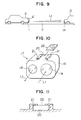
- Light emitted from the light emitting portion (light emitting element) 8 passes through the light emitting lens 10 and is formed into an outgoing light Lt, and a beam spot 15 irradiated on a distant object 13, for example, a vehicle ahead is formed into a substantially laterally lengthy elliptic shape as shown in Fig. 4.
- the irradiated light Lt is reflected in a reflex reflector 14 at the rear of the object 13 and formed into a reflecting light Lr, which is condensed by the light receiving lens 11 and received by the light receiving portion (light receiving element) 9.
- Figs. 5 and 6 show a second embodiment according to the present invention. Both a light emitting lens 10 and a light receiving lens lla are similarly deformation-worked.
- Fig. 7 is an optical explanatory view in the case where the aforementioned lenses 10 and 11a are used.
- the distance D2 between the light emitting portion and the light receiving portion is in the relation of D1 > D2, wherein D1 is the distance between the light emitting portion and the light receiving portion in the case of the first embodiment in which only the light emitting lens 10 is worked. Accordingly, the distance between the optical centers of the light emitting and receiving portions 8 and 9 is moved closer.
- a unit 17 in which a light receiving portion, a light emitting portion or light emitting and receiving portions (not shown) of an optical distance-measuring apparatus which forms a vehicular radar system are collectively incorporated.
- the box 16 is provided with an irradiation window 18 and a light receiving window 19.
- An irradiation beam Lt is irradiated from the irradiation window 18, and a light receiving beam Lr is inputted from the light receiving window 19.
- the unit 17 is assembled so that an angle of irradiation of the beam Lt is drawn to some extent and the beam is irradiated substantially horizontally to a road surface F in order that the beam Lt is positively irradiated on only the rear portion 14 of the vehicle ahead 13.
- the beam Lt is positively irradiated on the rear portion 14 of the vehicle ahead 13 as shown in Fig. 9 when the unit 17 has been mounted to the vehicle A, it is necessary that when the unit 17 is assembled, the beam irradiation angle coincides with the light receiving angle and also with the installation angle of the unit box 16, and when the unit 17 is mounted on the vehicle A, the horizontal angle of the vehicle coincides with the installation angle of the box 16.
- a horizontal reference surface 20 to be horizontal with the road surface F when mounted on the vehicle is provided on the upper portion of the box 16, and mounting plates 21 are provided on opposite ends of the horizontal reference surface 20.
- a level 22 is mounted by the mounting plates 21.
- the shape of the light emitting lens is deformation-worked, the shape of the radiation beam can be made variable.
- the distance between the light emitting portion (light emitting element) and the light receiving portion (light receiving element) can be moved closer to increase the quantity of receiving light.
- optical portions can be miniaturized, and apparatus can be also miniaturized. Mounting work can be simplified by the miniaturization of the optical portions.
- the horizontal reference surface is provided on the upper portion of the box and the level can be installed on the horizontal reference surface, the beam irradiation angle with respect to the box and the beam receiving angle when the unit is assembled are easily adjusted by use of the level. In addition, also when the unit is mounted on the vehicle, adjustment of angle can be easily made.
Landscapes
- Engineering & Computer Science (AREA)
- Physics & Mathematics (AREA)
- Computer Networks & Wireless Communication (AREA)
- General Physics & Mathematics (AREA)
- Radar, Positioning & Navigation (AREA)
- Remote Sensing (AREA)
- Electromagnetism (AREA)
- Optical Radar Systems And Details Thereof (AREA)
Claims (2)
- Optisches Radargerät für Fahrzeuge, mit einem Licht-emissionsabschnitt (8, 10) zum Abstrahlen von Signallicht (Lt) auf einen sich voraus befindenden Gegenstand und einem Lichtempfangsabschnitt (9, 11a) zum Empfangen von reflektiertem Licht (Lr) von dem Gegenstand,
dadurch gekennzeichnet,
daß eine Lichtemissionslinse (10) und eine Lichtempfangslinse (11, 11a) einzeln vorgesehen sind, von denen zumindest die Lichtemissionslinse (10) formändernd bearbeitet, d.h. teilweise abgeschnitten, ist, so daß ein Abstand (D1) zwischen optischen Zentren der Lichtemissions- und -empfangsabschnitte verkleinert werden kann und ein zwischen einer Einfallsachse des einlaufenden Lichts und dem auslaufenden Licht gebildeter Winkel (θ2) klein wird. - Optisches Radargerät für Fahrzeuge nach Anspruch 1, bei dem ein Lichtempfangsabschnitt (19), ein Lichtemissionsabschnitt (18) oder sowohl Lichtempfangs- als auch -emissionsabschnitt (19, 18) einer optischen Entfernungsmeßvorrichtung gemeinsam in einem Gehäuse (16) untergebracht sind, um eine Einheit (17) zu bilden,
dadurch gekennzeichnet, daß eine horizontale Referenzfläche (20), die bei Montage auf dem Fahrzeug horizontal bezüglich einer Straßenoberfläche (F) sein soll, auf dem oberen Abschnitt des Gehäuses vorgesehen ist und eine Libelle (22) auf der horizontalen Referenzfläche montiert ist.
Applications Claiming Priority (4)
| Application Number | Priority Date | Filing Date | Title |
|---|---|---|---|
| JP956391U JPH0499095U (de) | 1991-01-31 | 1991-01-31 | |
| JP9563/91U | 1991-01-31 | ||
| JP3045291U JPH04118685U (ja) | 1991-04-05 | 1991-04-05 | 車載用光レーダ装置 |
| JP30452/91U | 1991-04-05 |
Publications (2)
| Publication Number | Publication Date |
|---|---|
| EP0497364A1 EP0497364A1 (de) | 1992-08-05 |
| EP0497364B1 true EP0497364B1 (de) | 1997-04-02 |
Family
ID=26344321
Family Applications (1)
| Application Number | Title | Priority Date | Filing Date |
|---|---|---|---|
| EP92101613A Expired - Lifetime EP0497364B1 (de) | 1991-01-31 | 1992-01-31 | Optisches Radargerät für Fahrzeuge |
Country Status (4)
| Country | Link |
|---|---|
| US (1) | US5260710A (de) |
| EP (1) | EP0497364B1 (de) |
| CA (1) | CA2060349C (de) |
| DE (1) | DE69218640T2 (de) |
Families Citing this family (17)
| Publication number | Priority date | Publication date | Assignee | Title |
|---|---|---|---|---|
| IL100175A (en) * | 1991-11-27 | 1994-11-11 | State Of Isreal Ministry Of De | Vehicle collision warning device |
| FR2714186B1 (fr) * | 1993-09-06 | 1997-08-01 | Kansei Kk | Lentille de transmission de lumière d'une tête laser. |
| US5706140A (en) * | 1993-09-06 | 1998-01-06 | Kansei Corp. | Optical distance measuring equipment |
| JP3106045B2 (ja) * | 1993-11-25 | 2000-11-06 | 株式会社デンソー | レーダ装置 |
| DE59905312D1 (de) | 1999-02-25 | 2003-06-05 | Siemens Ag | Verfahren und Vorrichtung zum Erzeugen eines Positionsbildes eines Strahlung reflektierenden oder Strahlung streuenden Objekts oder einer Strahlung reflektierenden oder Strahlung streuenden Person |
| US6897819B2 (en) * | 2003-09-23 | 2005-05-24 | Delphi Technologies, Inc. | Apparatus for shaping the radiation pattern of a planar antenna near-field radar system |
| JP2005257324A (ja) * | 2004-03-09 | 2005-09-22 | Denso Corp | 距離検出装置 |
| DE102010042276A1 (de) * | 2010-10-11 | 2012-04-12 | Robert Bosch Gmbh | Sensor, Justageverfahren und Vermessungsverfahren für einen Sensor |
| DE102015109775B3 (de) * | 2015-06-18 | 2016-09-22 | RobArt GmbH | Optischer Triangulationssensor zur Entfernungsmessung |
| DE102015114883A1 (de) | 2015-09-04 | 2017-03-09 | RobArt GmbH | Identifizierung und Lokalisierung einer Basisstation eines autonomen mobilen Roboters |
| DE102015119501A1 (de) | 2015-11-11 | 2017-05-11 | RobArt GmbH | Unterteilung von Karten für die Roboternavigation |
| DE102015119865B4 (de) | 2015-11-17 | 2023-12-21 | RobArt GmbH | Robotergestützte Bearbeitung einer Oberfläche mittels eines Roboters |
| DE102015121666B3 (de) | 2015-12-11 | 2017-05-24 | RobArt GmbH | Fernsteuerung eines mobilen, autonomen Roboters |
| DE102016102644A1 (de) | 2016-02-15 | 2017-08-17 | RobArt GmbH | Verfahren zur Steuerung eines autonomen mobilen Roboters |
| US12140965B2 (en) | 2016-08-05 | 2024-11-12 | Rotrade Asset Management Gmbh | Method for controlling an autonomous mobile robot |
| EP3590014B1 (de) | 2017-03-02 | 2021-11-17 | Robart GmbH | Verfahren zur steuerung eines autonomen, mobilen roboters |
| DE102017109219A1 (de) | 2017-04-28 | 2018-10-31 | RobArt GmbH | Verfahren für die Roboternavigation |
Family Cites Families (25)
| Publication number | Priority date | Publication date | Assignee | Title |
|---|---|---|---|---|
| US3176294A (en) * | 1959-10-02 | 1965-03-30 | Bendix Corp | Vehicle radar system |
| FR2105124B1 (de) * | 1970-09-29 | 1974-03-01 | Mitsubishi Electric Corp | |
| US3749197A (en) * | 1971-05-12 | 1973-07-31 | B Deutsch | Obstacle detection system |
| US4195425A (en) * | 1972-07-17 | 1980-04-01 | Ernst Leitz Wetzlar Gmbh | System for measuring position and/or velocity |
| US3924232A (en) * | 1974-08-26 | 1975-12-02 | Itek Corp | Optical warning system |
| US4129775A (en) * | 1977-05-31 | 1978-12-12 | Hughes Aircraft Company | Glint capture system for improving lock stability of coat |
| JPS5596475A (en) * | 1979-01-19 | 1980-07-22 | Nissan Motor Co Ltd | Obstacle detector for vehicle |
| US4257703A (en) * | 1979-03-15 | 1981-03-24 | The Bendix Corporation | Collision avoidance using optical pattern growth rate |
| US4290043A (en) * | 1979-10-16 | 1981-09-15 | Kaplan Irwin M | Method of and system for detecting marine obstacles |
| DE3106539C2 (de) * | 1980-02-22 | 1994-09-01 | Ricoh Kk | Rasterobjektiv |
| US4326800A (en) * | 1980-05-05 | 1982-04-27 | Hughes Aircraft Company | Laser beam wavefront and line-of-sight error correction system |
| JPS5876784A (ja) * | 1981-10-31 | 1983-05-09 | Nissan Motor Co Ltd | 車両用光パルスレ−ダ装置 |
| JPS59203975A (ja) * | 1983-05-06 | 1984-11-19 | Nissan Motor Co Ltd | 車両用光レ−ダ装置 |
| CA1237798A (en) * | 1984-07-23 | 1988-06-07 | Anthony E. Dombrowski | Driver alerting device |
| US4662735A (en) * | 1985-01-16 | 1987-05-05 | Minolta Camera Kabushiki Kaisha | Plastic lens elements supporting structure |
| DE3507381A1 (de) * | 1985-03-02 | 1986-09-04 | Bosch Gmbh Robert | Vorrichtung zum schutze von kraftfahrzeug-insassen bei auffahrunfaellen |
| JPS61278775A (ja) * | 1985-06-03 | 1986-12-09 | Nissan Motor Co Ltd | 先行車検出装置 |
| DE3637165A1 (de) * | 1986-10-31 | 1988-05-05 | Rainer Ashauer | Verfahren und einrichtung zum verhindern von zusammenstoessen, insbesondere fuer kraftfahrzeuge im strassenverkehr |
| JPH0827352B2 (ja) * | 1988-02-22 | 1996-03-21 | トヨタ自動車株式会社 | 車両用先行車識別装置 |
| DE58903854D1 (de) * | 1988-03-16 | 1993-04-29 | Man Nutzfahrzeuge Ag | Aufprallvorrichtungssystem fuer nutzfahrzeuge. |
| DE3827879C1 (de) * | 1988-08-17 | 1989-08-24 | Daimler-Benz Aktiengesellschaft, 7000 Stuttgart, De | |
| US5003314A (en) * | 1989-07-24 | 1991-03-26 | Cubic Defense Systems, Inc. | Digitally synthesized phase error correcting system |
| US5057833A (en) * | 1989-11-07 | 1991-10-15 | Otl, Inc. | Passive optical air traffic alert system |
| US5028129A (en) * | 1990-01-05 | 1991-07-02 | Ball Corporation | Differential absorption ranging method and apparatus |
| US5061052A (en) * | 1990-07-27 | 1991-10-29 | Dejesus Ben L | Television picture enhancement device |
-
1992
- 1992-01-24 US US07/825,525 patent/US5260710A/en not_active Expired - Fee Related
- 1992-01-30 CA CA002060349A patent/CA2060349C/en not_active Expired - Fee Related
- 1992-01-31 EP EP92101613A patent/EP0497364B1/de not_active Expired - Lifetime
- 1992-01-31 DE DE69218640T patent/DE69218640T2/de not_active Expired - Fee Related
Also Published As
| Publication number | Publication date |
|---|---|
| DE69218640T2 (de) | 1997-07-10 |
| CA2060349A1 (en) | 1992-08-01 |
| CA2060349C (en) | 1999-09-21 |
| EP0497364A1 (de) | 1992-08-05 |
| DE69218640D1 (de) | 1997-05-07 |
| US5260710A (en) | 1993-11-09 |
Similar Documents
| Publication | Publication Date | Title |
|---|---|---|
| EP0497364B1 (de) | Optisches Radargerät für Fahrzeuge | |
| US5541724A (en) | Optical radar system for automotive vehicle | |
| US6067111A (en) | System for optical acquisition of the road | |
| US6119067A (en) | Object detecting system for conveyance, etc. | |
| US10137842B2 (en) | Camera system for a vehicle | |
| KR101777898B1 (ko) | 플래쉬 레이다 충돌 회피 시스템 | |
| KR930010453B1 (ko) | 차량 탑재 레이다 장치 | |
| US7499638B2 (en) | Object recognition apparatus | |
| DE19731754C2 (de) | Kombination Infrarot-Laser-Abstandssensoren mit Scheinwerfern | |
| US5313213A (en) | Device for aligning a directional antenna of a radar distance warning device of a vehicle | |
| DE112004000035B4 (de) | Sensoranordnung zur Abstands- und/oder Geschwindigkeitsmessung | |
| JP2022552293A (ja) | ライダーセンサの較正 | |
| EP0689080B1 (de) | Ringförmiger Laserfleck | |
| EP0561353A1 (de) | System zur Messung des Abstandes zwischen Fahrzeugen | |
| US5568136A (en) | Method and apparatus for identifying and measuring the distance between vehicles | |
| JPH09113262A (ja) | 走査距離計及び距離計を使用する走査方法 | |
| CN101073252A (zh) | 用于减少入射到摄像机中的杂散光的杂光光阑 | |
| JP4379791B2 (ja) | 走査装置 | |
| US5392111A (en) | Method of measuring and adjusting optical axis of headlight | |
| US5589930A (en) | Optical radar apparatus | |
| JP2003315442A (ja) | 車載レーダ装置の位置調整装置および位置調整方法 | |
| US20220003866A1 (en) | Optical module and distance-measuring device | |
| EP1831717B1 (de) | Optischer nahbereichssensor | |
| EP0615022B1 (de) | Anordnung zur optischen Datenübertragung | |
| JP3057157B2 (ja) | 移動体用物体検知装置 |
Legal Events
| Date | Code | Title | Description |
|---|---|---|---|
| PUAI | Public reference made under article 153(3) epc to a published international application that has entered the european phase |
Free format text: ORIGINAL CODE: 0009012 |
|
| AK | Designated contracting states |
Kind code of ref document: A1 Designated state(s): DE FR GB |
|
| RIN1 | Information on inventor provided before grant (corrected) |
Inventor name: SENOO, YASUSHI Inventor name: SUGIMURA, KAZUHIKO Inventor name: KITAMURA, HIDEKI Inventor name: SETO, TAKAO Inventor name: IWASAKI, KAZUHISA Inventor name: TANABE, TORU Inventor name: KIMURA, SHIGERU Inventor name: OMAMYUDA, YUKIO |
|
| 17P | Request for examination filed |
Effective date: 19920903 |
|
| 17Q | First examination report despatched |
Effective date: 19941019 |
|
| GRAG | Despatch of communication of intention to grant |
Free format text: ORIGINAL CODE: EPIDOS AGRA |
|
| GRAH | Despatch of communication of intention to grant a patent |
Free format text: ORIGINAL CODE: EPIDOS IGRA |
|
| GRAH | Despatch of communication of intention to grant a patent |
Free format text: ORIGINAL CODE: EPIDOS IGRA |
|
| GRAA | (expected) grant |
Free format text: ORIGINAL CODE: 0009210 |
|
| AK | Designated contracting states |
Kind code of ref document: B1 Designated state(s): DE FR GB |
|
| REF | Corresponds to: |
Ref document number: 69218640 Country of ref document: DE Date of ref document: 19970507 |
|
| ET | Fr: translation filed | ||
| PGFP | Annual fee paid to national office [announced via postgrant information from national office to epo] |
Ref country code: FR Payment date: 19980119 Year of fee payment: 7 |
|
| PG25 | Lapsed in a contracting state [announced via postgrant information from national office to epo] |
Ref country code: GB Free format text: LAPSE BECAUSE OF NON-PAYMENT OF DUE FEES Effective date: 19980131 |
|
| PLBE | No opposition filed within time limit |
Free format text: ORIGINAL CODE: 0009261 |
|
| STAA | Information on the status of an ep patent application or granted ep patent |
Free format text: STATUS: NO OPPOSITION FILED WITHIN TIME LIMIT |
|
| 26N | No opposition filed | ||
| PGFP | Annual fee paid to national office [announced via postgrant information from national office to epo] |
Ref country code: DE Payment date: 19980330 Year of fee payment: 7 |
|
| GBPC | Gb: european patent ceased through non-payment of renewal fee |
Effective date: 19980131 |
|
| PG25 | Lapsed in a contracting state [announced via postgrant information from national office to epo] |
Ref country code: FR Free format text: LAPSE BECAUSE OF NON-PAYMENT OF DUE FEES Effective date: 19990930 |
|
| PG25 | Lapsed in a contracting state [announced via postgrant information from national office to epo] |
Ref country code: DE Free format text: LAPSE BECAUSE OF NON-PAYMENT OF DUE FEES Effective date: 19991103 |
|
| REG | Reference to a national code |
Ref country code: FR Ref legal event code: ST |