EP0497437A2 - Vorrichtung zum Auswerfen von Formteilen aus einer Spritzgiessmaschine - Google Patents
Vorrichtung zum Auswerfen von Formteilen aus einer Spritzgiessmaschine Download PDFInfo
- Publication number
- EP0497437A2 EP0497437A2 EP92250016A EP92250016A EP0497437A2 EP 0497437 A2 EP0497437 A2 EP 0497437A2 EP 92250016 A EP92250016 A EP 92250016A EP 92250016 A EP92250016 A EP 92250016A EP 0497437 A2 EP0497437 A2 EP 0497437A2
- Authority
- EP
- European Patent Office
- Prior art keywords
- rod
- coupling
- ejector
- piston
- ejection device
- Prior art date
- Legal status (The legal status is an assumption and is not a legal conclusion. Google has not performed a legal analysis and makes no representation as to the accuracy of the status listed.)
- Granted
Links
Images

Classifications
-
- B—PERFORMING OPERATIONS; TRANSPORTING
- B29—WORKING OF PLASTICS; WORKING OF SUBSTANCES IN A PLASTIC STATE IN GENERAL
- B29C—SHAPING OR JOINING OF PLASTICS; SHAPING OF MATERIAL IN A PLASTIC STATE, NOT OTHERWISE PROVIDED FOR; AFTER-TREATMENT OF THE SHAPED PRODUCTS, e.g. REPAIRING
- B29C45/00—Injection moulding, i.e. forcing the required volume of moulding material through a nozzle into a closed mould; Apparatus therefor
- B29C45/17—Component parts, details or accessories; Auxiliary operations
- B29C45/1775—Connecting parts, e.g. injection screws, ejectors, to drive means
-
- B—PERFORMING OPERATIONS; TRANSPORTING
- B29—WORKING OF PLASTICS; WORKING OF SUBSTANCES IN A PLASTIC STATE IN GENERAL
- B29C—SHAPING OR JOINING OF PLASTICS; SHAPING OF MATERIAL IN A PLASTIC STATE, NOT OTHERWISE PROVIDED FOR; AFTER-TREATMENT OF THE SHAPED PRODUCTS, e.g. REPAIRING
- B29C45/00—Injection moulding, i.e. forcing the required volume of moulding material through a nozzle into a closed mould; Apparatus therefor
- B29C45/17—Component parts, details or accessories; Auxiliary operations
- B29C45/40—Removing or ejecting moulded articles
- B29C45/4005—Ejector constructions; Ejector operating mechanisms
Definitions
- the invention relates to a device for ejecting molded parts from an injection molding machine with a laterally movable ejector rod to which an evaluator can be coupled.
- an ejection device for injection molding machines in which hydraulically operated ejector pins are arranged on an ejector plate.
- the ejector pins are fastened to the piston of a hydraulic drive with the ejector by screw connections.
- the invention has never set itself the goal of creating an ejector with a compact coupling which enables a play-free power transmission, which is easily separable and, on the machine side, does not require a travel path required beyond the ejector stroke.
- the invention achieves this aim by the characterizing features of claim 1.
- the subclaims contain advantageous configurations of the ejection device.
- the ejector according to the invention has a sleeve coupling.
- the sleeve is preferably attached to the tool base plate and axially arranged so that it protrudes only to a small extent and thus with little disability into the space between the base plate and the ejector cylinder.
- the head of the ejector rod can be inserted into the sleeve.
- the ejector rod has a telescopic coupling rod on the head side, the end of which corresponds dimensionally to the sleeve.
- the drive for laterally moving the coupling rod is preferably actuated hydraulically, with the usually existing hydraulics also being used.
- the head end of the actuating rod is tapered.
- the cone corresponds to the preferably also conical inner surface of the sleeve-shaped coupling rod.
- slots are provided that point in the axial direction.
- the switchable coupling in question does not go any way in the end position range lost the open phase.
- the rear area in particular namely the distance from the cylinder base to the piston base area of the main piston, is required for the end position damping of the ejector.
- An actuating rod can also be arranged next to the actuating piston, which in the end position of the "coupled” position enables the clutch piston to be easily detached from the actuating piston.
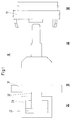
- FIG. 1 shows a part of a tool base plate 11 of an injection molding machine (not shown further).
- a cylinder 21 of the ejector device 20 is shown as a sketch.
- a piston 22 is arranged in the cylinder 21, to which a piston rod 31 of an ejector rod 30 is fastened.
- a clutch 40 is arranged on an ejector plate 31.
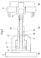
- FIGS. 2 and 3 show in detail the structure of the coupling 40, which is connected to an ejector plate 50, which is only shown in sketch form.
- the coupling 40 designed as a sleeve coupling has one Coupling sleeve 44, which can be guided through a tool base plate 11 of the injection molding machine in the direction of the axis of the sleeve.
- the end of the coupling sleeve 44 facing away from the ejector plate 31 is held in the ejector plate 50.
- the head of a coupling rod 43 can be inserted into the coupling sleeve 44.
- the coupling rod 43 has at the end facing away from the sleeve 44 a coupling piston 42 which is arranged in a coupling cylinder 41.
- the clutch cylinder 41 is attached to the ejector plate 31.
- the coupling rod 43 is designed as a tube.
- An actuating rod 46 can be moved linearly in the tubular coupling rod 43.
- the actuating rod 46 is tapered on the head side and has an actuating piston 45 on the foot side, which is arranged in addition to the clutch piston 42 in the clutch cylinder 41.
- By moving the coupling rod 43 and the fastening rod 46 relative to one another the head region of the coupling rod 43 is widened after being inserted into the sleeve 44, so that a non-positive and positive connection is achieved.
- the coupling rod 43 has a parting line 49, on which the coupling rod can be separated axially.
- An annular piston 48 is provided on the actuating rod and can be moved in a chamber 47 incorporated into the sleeve-shaped coupling rod 43. This small annular piston 48 supports the displacement of the actuating rod 46 relative to the coupling rod 43, in particular if the two pistons 45 and 42 lie very close to one another.
Landscapes
- Engineering & Computer Science (AREA)
- Manufacturing & Machinery (AREA)
- Mechanical Engineering (AREA)
- Moulds For Moulding Plastics Or The Like (AREA)
- Injection Moulding Of Plastics Or The Like (AREA)
- Disintegrating Or Milling (AREA)
- Elimination Of Static Electricity (AREA)
- Feeding And Guiding Record Carriers (AREA)
- Processing And Handling Of Plastics And Other Materials For Molding In General (AREA)
Abstract
Description
- Die Erfindung betrifft eine Vorrichtung zum Auswerfen von Formteilen aus einer Spritzgießmaschine mit einer lateral bewegbaren Auswerferstange, an die ein Auswerter kuppelbar ist.
- Aus der DE-OS 35 42 878 ist eine Auswerfeinrichtung für Spritzgießmaschinen bekannt, bei der an einer Auswerferplatte hydraulisch betätigbare Auswerferstifte angeordnet sind. Die Auswerferstifte sind dabei durch Schraubverbindungen an dem Kolben eines hydraulischen Antriebs mit der Auswerfeinrichtung befestigt.
- Diese lösbare Schraubverbindung gibt keinen Hinweis auf eine leicht trennbare, ohne manuellen Eingriff mögliche Verbindung. Zum Auseinanderschrauben wird der komplette Demontagehub benötigt.
- Aus der EP-OS 02 33 113 ist eine Kupplung für eine Auswurfeinrichtung bekannt, bei der eine kolbenförmige Stange in eine Hülse einsteckbar und durch radial verschiebbare Stifte formschlüssig arretierbar ist.
- Bei dieser Kupplungsform wird zum Entkuppeln der volle Weg entsprechend der Überdeckung von Vater- und Mutterteilen benötigt. Dieser Weg fehlt nach dem Ankuppeln dem maschinenseitig möglichen Auswerferhub. Die rein formschlüssige Verbindung der aus dieser Schrift bekannten Kupplung hat weiterhin den Nachteil, daß zwischen den zu verbindenen Bauteilen ein Spiel und darüber hinaus ein Verdrehen der Kupplungsstange relativ zur Kolbenstange möglich ist.
- In Kenntnis der genannten Nachteile hat sich nie Erfindung zum Ziel gesetzt, einen Auswerfer mit einer kompakten, eine spielfreie Kraftübertragung ermöglichenden Kupplung zu schaffen, die leicht trennbar ist und dabei maschinenseitig keinen über den Auswerferhub hinaus erforderlichen Verfahrweg benötigt.
- Die Erfindung erreicht dieses Ziel durch die kennzeichnenden Merkmale des Anspruchs 1. Die Unteransprüche enthalten vorteilhafte Ausgestaltungen der Auswurfeinrichtung.
- Der erfindungsgemäße Auswerfer weist eine Hülsenkupplung auf. Die Hülse ist dabei vorzugsweise an der Werkzeuggrundplatte befestigt und axial so angeordnet, daß sie nur in geringem Maße und damit behinderungsarm in den Freiraum zwischen der Grundplatte und dem Auswerferzylinder hineinragt.
- In die Hülse ist der Kopf der Auswerferstange einführbar. Die Auswerferstange weist dabei kopfseitig eine teleskopförmig ausziebare kupplungsstange auf, deren Ende maßlich mit der Hülse korrespondiert.
- Der Antrieb zum lateralen Bewegen der Kupplungsstange wird vorzugsweise hydraulisch betätigt, wobei die üblicherweise vorhandene Hydraulik mitbenutzt wird.
- Im gekuppelten Zustand werden an dem vorderen Teil der Kupplungsstange radial nach außen gerichtete Kräfte aufgebracht, die über die Formanpassung hinaus Klemmkräfte zwischen Hülse und Stange wirken lassen. Diese Kräfte sind ausreichend hoch, da eine relativ große Kolbenfläche zur Verfügung steht.
- In baulich einfacher Weise wird dieses form- und kraftschlüssige Verbinden durch eine in die hülsenförmig ausgestaltete Kupplungsstange zentrisch eingebrachte Betätigungsstange erreicht.
- Das kopfseitige Ende der Betätigungsstange ist dabei konisch angespitzt. Der Konus korrespondiert mit der vorzugsweise ebenfalls konisch ausgebildeten Innenflache der hülsenförmigen Kupplungsstange. Zur einfachen Durchmesservergrößerung des Kupplungsstangenkopfes sind in axiale Richtung weisende Schlitze vorgesehen.
- Bei der im gekuppelten Zustand form- und kraftschlüssig verbundenen Kopfenden der Kupplungsstange mit der Betätigungsstange und der Kupplungshülse ist jegliches kupplungsspiel verhinderbar. Eine hohe Betriebssicherheit ist dadurch gewährleistet. Darüber hinaus ist bei einfachem Aufbau eine hohe Reproduzierbarkeit des Kupplungsvorganges möglich.
- Im Gegensatz zu vergleichbaren Auswerfern an Spritzgießmaschinen, bei denen der Hauptkolben zum Kuppeln eingesetzt wird, geht bei der vorliegenden schaltbaren Kupplung keinerlei Weg im Endlagenbereich in der Offenphase verloren. Gerade der hintere Bereich, nämlich der Abstand des Zylinderbodens zur Kolbengrundfläche des Hauptkolbens, wird bei der Endlagendämpfung des Auswerfers benötigt.
- Eine Betätigungsstange ist zusätzlich neben dem Betätigungskolben noch anordnenbar, der in der Endlage der Stellung "gekuppelt" ein einfaches Lösen der Kupplungskolben vom Betätigungskolben ermöglicht.
- Ein Beispiel der Erfindung ist in der beigefügten Zeichnung dargelegt. Es zeigen:
- Fig. 1
- Übersicht der Auswerfervorrichtung,
- Fig. 2
- Auswerfervorrichtung in entkuppelter Position,
- Fig. 3
- Auswerfervorrichtung in gekuppelter Position.
- In der Fig. 1 ist ein Teil einer Werkzeuggrundplatte 11 einer nicht weiter dargestellten Spritzgießmaschine aufgezeigt. In Richtung der Zentralachse I ist ein Zylinder 21 der Auswerfervorrichtung 20 skizzenhaft dargestellt. Im Zylinder 21 ist ein Kolben 22 angeordnet, an dem eine Kolbenstange 31 einer Auswerferstange 30 befestigt ist. Am Kopfende der Kolbenstange 32 ist an einer Auswerferplatte 31 eine Kupplung 40 angeordnet.
- Die Fig. 2 und 3 zeigen im Detail den Aufbau der Kupplung 40, die mit einer nur skizzenhaft dargestellten Auswerferplatte 50 verbunden ist. Die als Hülsenkupplung ausgeführte Kupplung 40 weist dabei eine Kupplungshülse 44 auf, die durch eine Werkzeuggrundplatte 11 der Spritzgießmaschine in Richtung der Achse der Hülse führbar ist. Das der Auswerferplatte 31 abgewandte Ende der Kupplungshülse 44 ist in der Auswerferplatte 50 gehaltert.
- In die Kupplungshülse 44 ist der Kopf einer Kupplungsstange 43 einführbar. Die Kupplungsstange 43 hat an dem der Hülse 44 abgewandten Ende einen Kupplungskolben 42, der in einem Kupplungszylinder 41 angeordnet ist.
- Der Kupplungszylinder 41 ist an der Auswerferplatte 31 befestigt.
- Die Kupplungsstange 43 ist als Rohr ausgebildet. In der rohrförmigen Kupplungsstange 43 ist eine Betätigungsstange 46 linear bewegbar. Die Betätigungsstange 46 ist kopfseitig, konisch angespitzt und weist fußseitig einen Betätigungskolben 45 auf, der zusätzlich zum Kupplungskolben 42 im Kupplungszylinder 41 angeordnet ist.
Durch eine Relativverschiebung von Kupplungsstange 43 und Befestigungsstange 46 zueinander wird der Kopfbereich der Kupplungsstange 43 nach dem Einstecken in die Hülse 44 aufgeweitet, so daß damit eine kraft- und formschlüssige Verbindung erreicht wird. Die Kupplungsstange 43 weist eine Teilfuge 49 auf, an der die Kupplungsstange axial trennbar ist. - An der Betätigungsstange ist ein Ringkolben 48 vorgesehen, der in einer in die hülsenförmige Kupplungsstange 43 eingearbeiteten Kammer 47 bewegbar ist. Dieser kleine Ringkolben 48 unterstützt die Verschiebung der Betätigungsstange 46 relativ zu der Kupplungsstange 43, insbesondere wenn die beiden Kolben 45 und 42 sehr dicht aneinanderliegen.
-
- 10
- Spritzgießmaschine
- 11
- Werkzeuggrundplatte
- 20
- Auswerfervorrichtung
- 21
- Zylinder
- 22
- Kolben
- 30
- Auswerferstange
- 31
- Auswerferplatte
- 32
- Kolbenstange
- 40
- Kupplung
- 41
- Kupplungszylinder
- 42
- Kupplungskolben
- 43
- Kupplungsstange
- 44
- Kupplungshülse
- 45
- Betätigungskolben
- 46
- Betätigungsstange
- 47
- Kammer
- 48
- Ringkolben
- 48
- Teilfuge
- 50
- Auswerferplatte
- I
- Zentralachse
Claims (10)
- Vorrichtung zum Auswerfen von Formteilen aus einer Spritzgießmaschine, mit einer linear bewegbaren Auswerferstange, an die ein Auswerfer kuppelbar ist,
dadurch gekennzeichnet,
daß eine schaltbare, teleskopförmige Hülsenkupplung (40) vorgesehen ist, die den Auswerfer (50) mit der Auswerferstange (30) form- und kraftschlüssig verbindet. - Vorrichtung zum Auswerfen nach Anspruch 1,
dadurch gekennzeichnet,
daß die Kupplung (40) einen Hydraulik-Zylinder (41) aufweist, in dem ein Kupplungskolben (42), der mit einer Kupplungsstange (43) versehen ist, bewegbar ist, deren kopfseitiges Ende axial in eine mit dem Auswerfer (50) verbundene Kupplungshülse (44) einsteckbar und dann arretierbar ist. - Vorrichtung zum Auswerten nach Anspruch 2,
dadurch gekennzeichet,
daß die Kupplungskolbenstange (43) ein Rohr ist, in dem eine mit einem Betätigungskolben (45) versehene Betätigungsstange (46) axial verschiebbar ist. - Vorrichtung zum Auswerfen nach Anspruch 3,
dadurch gekennzeichnet,
daß das kopfseitige Ende der rohrförmigen Kupplungskolbenstange (43) eine radial nach innen weisende Verdickung der Rohrwand besitzt. - Vorrichtung zum Auswerfen nach Anspruch 3,
dadurch gekennzeichnet,
daß die Betätigungsstange (46) kopfseitig konisch angespitzt ist. - Vorrichtung zum Auswerfen nach Anspruch 2,
dadurch gekennzeichnet,
daß die Kupplungshülse (44) der Kupplungskolbenstange (43) zugewandt eine radial nach innen weisende Verengung aufweist. - Vorrichtung zum Auswerten nach den Ansprüchen 4 bis 6,
dadurch gekennzeichnet,
daß die im eingekuppelten Betriebszustand sich berührenden Flächen der Kupplungshülse (44) und der Kupplungsstange (43) sowie der Betätigungsstange (46) in der Weise angepaßt sind, daß bei in die Kupplungshülse (44) eingesteckter Kupplungsstange (43) und hülsenwärts verfahrener Betätigungsstange (46) eine Relativbewegung Zwischen dem Auswerfer (50) und der Auswerferstange (30) verhindert wird. - Vorrichtung zum Auswerfen nach Anspruch 4,
dadurch gekennzeichnet,
daß an der rohrförmigen Kupplungsstange (43) im Bereich der Verdickung in axialer Richtung weisende Schlitze vorgesehen sind. - Vorrichtung zum Auswerfen nach Anspruch 3,
dadurch gekennzeichnet,
daß die rohrförmige Kupplungsstange (43) radial teilbar ist und im Bereich der Teilfuge (49) eine ringförmige Kammer (47) aufweist. - Vorrichtung zum Auswerfen nach Anspruch 9,
dadurch gekennzeichnet,
daß an der Betätigungsstange (46) ein Ringkolben (48) vorgesehen ist, der in der Kammer (47) axial bewegbar ist.
Applications Claiming Priority (2)
| Application Number | Priority Date | Filing Date | Title |
|---|---|---|---|
| DE4103446 | 1991-02-01 | ||
| DE4103446A DE4103446C2 (de) | 1991-02-01 | 1991-02-01 | Vorrichtung zum auswerfen von formteilen aus einer spritzgiessmaschine |
Publications (3)
| Publication Number | Publication Date |
|---|---|
| EP0497437A2 true EP0497437A2 (de) | 1992-08-05 |
| EP0497437A3 EP0497437A3 (en) | 1993-01-27 |
| EP0497437B1 EP0497437B1 (de) | 1995-05-24 |
Family
ID=6424418
Family Applications (1)
| Application Number | Title | Priority Date | Filing Date |
|---|---|---|---|
| EP92250016A Expired - Lifetime EP0497437B1 (de) | 1991-02-01 | 1992-01-21 | Vorrichtung zum Auswerfen von Formteilen aus einer Spritzgiessmaschine |
Country Status (4)
| Country | Link |
|---|---|
| US (1) | US5252057A (de) |
| EP (1) | EP0497437B1 (de) |
| AT (1) | ATE122960T1 (de) |
| DE (2) | DE4103446C2 (de) |
Families Citing this family (6)
| Publication number | Priority date | Publication date | Assignee | Title |
|---|---|---|---|---|
| DE19831223C2 (de) * | 1998-07-02 | 2002-01-24 | Demag Ergotech Wiehe Gmbh | Verfahren zum Auswerfen von Kunststoffteilen aus einer Spritzgießmaschine und Vorrichtung zur Durchführung des Verfahrens |
| US6638467B1 (en) | 1999-08-16 | 2003-10-28 | Green Tokai Co., Ltd. | Molding ejector plate structure and method of ejecting molded articles from mold cavity therewith |
| US6315544B1 (en) | 1999-10-07 | 2001-11-13 | Burger Engineering, Inc. | Adjustable length extension bars for connecting a mold ejector plate to a press ejector plate |
| IT248150Y1 (it) * | 1999-11-03 | 2002-12-10 | Sipa Spa | Barra di comando per piastra porta-stampi |
| US7309227B2 (en) * | 2005-08-23 | 2007-12-18 | Pierson Theodore J | Polymeric injection mold with retractable bars for producing re-entrant molded surfaces |
| CN107599492B (zh) * | 2017-09-28 | 2019-07-23 | 江苏唯侓机器人科技有限公司 | 一种通用模具顶针 |
Family Cites Families (12)
| Publication number | Priority date | Publication date | Assignee | Title |
|---|---|---|---|---|
| BE434744A (de) * | ||||
| US3591898A (en) * | 1969-09-22 | 1971-07-13 | Herter Inc S | Molding of all-plastic shot shell cases |
| DE2314243A1 (de) * | 1972-10-03 | 1974-04-18 | Guenter Huetter | Einrichtung zum vorschuu und zur rueckholung einer auswerferplatte an formwerkzeugen fuer spritzgussmaschinen |
| FR2414998A1 (fr) * | 1978-01-18 | 1979-08-17 | Guen & Hemidy Le | Verin d'ejection pour presses a mouler par injection |
| FR2460132A1 (fr) * | 1979-06-28 | 1981-01-23 | Yon Koui Asan | Nouvelles lotions capillaires de lutte contre la chute des cheveux |
| FR2570640B1 (fr) * | 1984-09-26 | 1987-03-20 | Vallet Marc | Attelage d'ejection pour presse a injecter |
| DE3542878A1 (de) * | 1985-12-02 | 1987-06-11 | Stuebbe Gmbh Maschf | Auswerfereinrichtung fuer spritzgiessmaschinen |
| FR2593436B1 (fr) * | 1986-01-30 | 1989-06-30 | Aerospatiale | Dispositif d'ejection et de rappel d'ejection d'une piece dans une machine |
| US4731014A (en) * | 1986-03-12 | 1988-03-15 | Holdt J W Von | Rear opening mold |
| SU1546269A1 (ru) * | 1988-03-09 | 1990-02-28 | Предприятие П/Я Р-6816 | Литьева форма с двухступенчатой системой выталкивани |
| FR2629529B1 (de) * | 1988-04-01 | 1990-12-28 | Aerospatiale | |
| US4832307A (en) * | 1988-09-15 | 1989-05-23 | Toshiba Kikai Kabushiki Kaisha | Injection mold |
-
1991
- 1991-02-01 DE DE4103446A patent/DE4103446C2/de not_active Expired - Fee Related
-
1992
- 1992-01-21 AT AT92250016T patent/ATE122960T1/de not_active IP Right Cessation
- 1992-01-21 EP EP92250016A patent/EP0497437B1/de not_active Expired - Lifetime
- 1992-01-21 DE DE59202274T patent/DE59202274D1/de not_active Expired - Fee Related
- 1992-01-31 US US07/829,761 patent/US5252057A/en not_active Expired - Fee Related
Also Published As
| Publication number | Publication date |
|---|---|
| US5252057A (en) | 1993-10-12 |
| DE4103446A1 (de) | 1992-08-13 |
| DE59202274D1 (de) | 1995-06-29 |
| DE4103446C2 (de) | 1993-11-04 |
| EP0497437A3 (en) | 1993-01-27 |
| ATE122960T1 (de) | 1995-06-15 |
| EP0497437B1 (de) | 1995-05-24 |
Similar Documents
| Publication | Publication Date | Title |
|---|---|---|
| DE19534546B4 (de) | Spritzmaschine mit Vibrationseinrichtung | |
| DE2638503C2 (de) | Vorrichtung zum Anformen einer Verbindungsmuffe | |
| EP1072554B1 (de) | Kran mit einem Teleskopausleger | |
| EP0360189A2 (de) | Spritzdüse für eine Spritzgussmaschine | |
| DE2162186A1 (de) | Automatische Ölungsanordnung für eine Spritz gußmaschine | |
| EP0350516B1 (de) | Spannfutter-Schnellwechseleinrichtung | |
| EP3581360A1 (de) | Spritzgiesswerkzeug | |
| EP0137961B2 (de) | Ausziehvorrichtung für einen Gasspülstein | |
| EP0497437B1 (de) | Vorrichtung zum Auswerfen von Formteilen aus einer Spritzgiessmaschine | |
| EP0714749B1 (de) | Einrichtung zum Entfernen von gegossenen Formteilen | |
| WO2000012285A1 (de) | Verfahren und vorrichtung zum spritzgiess en einer kunststoffmasse | |
| EP0484315A2 (de) | Spritzwerkzeug | |
| EP0183278B1 (de) | Verfahren und Vorrichtung zur Herstellung eines langen Kunststoffrohrs durch Spritzguss | |
| DE2605394B2 (de) | Vorrichtung zum Herausziehen mindestens einer Säule einer Spritzgießmaschine | |
| EP0657268B1 (de) | Verfahren und Vorrichtung zum Spritzgiessen von mehrschichtigen Gegenständen | |
| DE19819684A1 (de) | Klinkenzug an Formungswerkzeugen | |
| DE2111978A1 (de) | Spritzeinheit fuer Spritzgiessmaschine | |
| DE2109765C3 (de) | Spritzgießmaschine für thermoplastische Massen mit wenigstens einer einsteckbaren Einspritzeinheit | |
| DE3916193A1 (de) | Hydraulische schliesseinheit | |
| DE2639665C2 (de) | Strangpreßkopf zum Herstellen eines hohlen Stranges aus thermoplastischem Kunststoff | |
| DE4224195C2 (de) | Spritzgießmaschine | |
| DE4446692A1 (de) | Formschließeinrichtung für Kunststoffspritzgießmaschinen | |
| DE10224708C1 (de) | Zusammenfallbarer Kern für Spritzwerkzeuge | |
| DE3430872C2 (de) | Vorrichtung zum Spritzgießen von Formteilen | |
| DE3614119C2 (de) |
Legal Events
| Date | Code | Title | Description |
|---|---|---|---|
| PUAI | Public reference made under article 153(3) epc to a published international application that has entered the european phase |
Free format text: ORIGINAL CODE: 0009012 |
|
| AK | Designated contracting states |
Kind code of ref document: A2 Designated state(s): AT CH DE FR GB IT LI NL |
|
| PUAL | Search report despatched |
Free format text: ORIGINAL CODE: 0009013 |
|
| AK | Designated contracting states |
Kind code of ref document: A3 Designated state(s): AT CH DE FR GB IT LI NL |
|
| 17P | Request for examination filed |
Effective date: 19930317 |
|
| 17Q | First examination report despatched |
Effective date: 19940913 |
|
| GRAA | (expected) grant |
Free format text: ORIGINAL CODE: 0009210 |
|
| AK | Designated contracting states |
Kind code of ref document: B1 Designated state(s): AT CH DE FR GB IT LI NL |
|
| PG25 | Lapsed in a contracting state [announced via postgrant information from national office to epo] |
Ref country code: FR Effective date: 19950524 Ref country code: NL Free format text: LAPSE BECAUSE OF FAILURE TO SUBMIT A TRANSLATION OF THE DESCRIPTION OR TO PAY THE FEE WITHIN THE PRESCRIBED TIME-LIMIT Effective date: 19950524 Ref country code: GB Effective date: 19950524 Ref country code: IT Free format text: LAPSE BECAUSE OF FAILURE TO SUBMIT A TRANSLATION OF THE DESCRIPTION OR TO PAY THE FEE WITHIN THE PRE;WARNING: LAPSES OF ITALIAN PATENTS WITH EFFECTIVE DATE BEFORE 2007 MAY HAVE OCCURRED AT ANY TIME BEFORE 2007. THE CORRECT EFFECTIVE DATE MAY BE DIFFERENT FROM THE ONE RECORDED.SCRIBED TIME-LIMIT Effective date: 19950524 |
|
| REF | Corresponds to: |
Ref document number: 122960 Country of ref document: AT Date of ref document: 19950615 Kind code of ref document: T |
|
| REF | Corresponds to: |
Ref document number: 59202274 Country of ref document: DE Date of ref document: 19950629 |
|
| EN | Fr: translation not filed | ||
| NLV1 | Nl: lapsed or annulled due to failure to fulfill the requirements of art. 29p and 29m of the patents act | ||
| GBV | Gb: ep patent (uk) treated as always having been void in accordance with gb section 77(7)/1977 [no translation filed] |
Effective date: 19950524 |
|
| PLBE | No opposition filed within time limit |
Free format text: ORIGINAL CODE: 0009261 |
|
| 26N | No opposition filed | ||
| REG | Reference to a national code |
Ref country code: CH Ref legal event code: PUE Owner name: VODAFONE AG TRANSFER- DEMAG ERGOTECH GMBH Ref country code: CH Ref legal event code: PFA Free format text: MANNESMANN AKTIENGESELLSCHAFT TRANSFER- VODAFONE AG |
|
| PGFP | Annual fee paid to national office [announced via postgrant information from national office to epo] |
Ref country code: AT Payment date: 20040102 Year of fee payment: 13 |
|
| PGFP | Annual fee paid to national office [announced via postgrant information from national office to epo] |
Ref country code: CH Payment date: 20040106 Year of fee payment: 13 |
|
| PGFP | Annual fee paid to national office [announced via postgrant information from national office to epo] |
Ref country code: DE Payment date: 20040108 Year of fee payment: 13 |
|
| PG25 | Lapsed in a contracting state [announced via postgrant information from national office to epo] |
Ref country code: AT Free format text: LAPSE BECAUSE OF NON-PAYMENT OF DUE FEES Effective date: 20050121 |
|
| PG25 | Lapsed in a contracting state [announced via postgrant information from national office to epo] |
Ref country code: LI Free format text: LAPSE BECAUSE OF NON-PAYMENT OF DUE FEES Effective date: 20050131 Ref country code: CH Free format text: LAPSE BECAUSE OF NON-PAYMENT OF DUE FEES Effective date: 20050131 |
|
| PG25 | Lapsed in a contracting state [announced via postgrant information from national office to epo] |
Ref country code: DE Free format text: LAPSE BECAUSE OF NON-PAYMENT OF DUE FEES Effective date: 20050802 |
|
| REG | Reference to a national code |
Ref country code: CH Ref legal event code: PL |