EP0497472A1 - Gasturbinentriebwerk mit einem am rückwärtigen Ende angeordneten Bläser - Google Patents
Gasturbinentriebwerk mit einem am rückwärtigen Ende angeordneten Bläser Download PDFInfo
- Publication number
- EP0497472A1 EP0497472A1 EP92300386A EP92300386A EP0497472A1 EP 0497472 A1 EP0497472 A1 EP 0497472A1 EP 92300386 A EP92300386 A EP 92300386A EP 92300386 A EP92300386 A EP 92300386A EP 0497472 A1 EP0497472 A1 EP 0497472A1
- Authority
- EP
- European Patent Office
- Prior art keywords
- fan
- compressor
- turbine
- engine
- shaft
- Prior art date
- Legal status (The legal status is an assumption and is not a legal conclusion. Google has not performed a legal analysis and makes no representation as to the accuracy of the status listed.)
- Withdrawn
Links
Images


Classifications
-
- F—MECHANICAL ENGINEERING; LIGHTING; HEATING; WEAPONS; BLASTING
- F02—COMBUSTION ENGINES; HOT-GAS OR COMBUSTION-PRODUCT ENGINE PLANTS
- F02K—JET-PROPULSION PLANTS
- F02K3/00—Plants including a gas turbine driving a compressor or a ducted fan
- F02K3/02—Plants including a gas turbine driving a compressor or a ducted fan in which part of the working fluid by-passes the turbine and combustion chamber
- F02K3/04—Plants including a gas turbine driving a compressor or a ducted fan in which part of the working fluid by-passes the turbine and combustion chamber the plant including ducted fans, i.e. fans with high volume, low pressure outputs, for augmenting the jet thrust, e.g. of double-flow type
- F02K3/062—Plants including a gas turbine driving a compressor or a ducted fan in which part of the working fluid by-passes the turbine and combustion chamber the plant including ducted fans, i.e. fans with high volume, low pressure outputs, for augmenting the jet thrust, e.g. of double-flow type with aft fan
Definitions
- This application relates to an improvement of the engine disclosed in EP Application 91 308553.6, for Integrated Propulsion System, assigned to the assignee of this application.
- the invention relates to an integrated, aft fan, gas turbine engine.
- Gas turbine engines require a number of support systems in order to render the engine operational.
- Such systems comprise, for example, intake, exhaust, fuel supply, electrical, cooling, lubrication, mounting, starting, and control systems.
- the associated systems are typically mounted externally of the engine, or installed within the vehicle and connected to the engine by means of ducts, tubing, hoses, wires, harnesses, etc. Interfaces between the engine and its associated components become increasingly complex as the number of associated systems increases.
- the propulsion system comprises the load transfer mechanism between the fore and aft sections of an aircraft.
- the propulsion system must be capable of withstanding loads experienced during aircraft maneuvers, e.g. vehicle roll, pitch and yaw.
- the aft fan gas turbine engine and its associated support systems of the invention are structurally integrated, greatly simplifying component interface and installation problems.
- the engine includes a forward assembly comprising an annular integral fuel tank, air inlet, fuel pump, front compressor rotor bearing support, and compressor rotor and stator.
- An intermediate assembly comprises a combustor, turbine nozzle and turbine.
- the rear assembly comprises a rear spool, fan, turbine rotor bearing support, turbine exhaust ducts, fan air intake, fan, and starting system.
- Self-lubricated bearings are used eliminating the need for an external lubrication system.
- a pyrotechnic starter and igniter provide one-shot operation. External air crank and ignition or a conventional starter and start procedure can be used for multiple starts, if desired.
- FIGS. 1 and 2 comprise a composite cross-sectional elevation of an integrated propulsion system constructed in accordance with the instant invention.
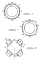
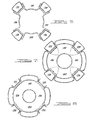
- FIG. 3 is a view taken along the line 3-3 of FIG. 2.
- FIG. 4 is a view taken along the line 4-4 of FIG. 2.
- FIG. 5 is a view taken along the line 5-5 of FIG. 2.
- FIG. 6 is a view taken along the line 6-6 of FIG. 2.
- FIG. 7 is a view taken along the line 7-7 of FIG. 2.
- FIG. 8 is a view taken along the line 8-8 of FIG. 2.
- a propulsion system 10 constructed in accordance with a preferred embodiment of the instant invention, comprises a generally cylindrical structurally integrated assembly to which all of the components of the system are either attached, contained internally, or formed integrally therewith.
- the major structural components of the system 10 comprise an intermediate combustor housing 12, forward air inlet housing 14, and an aft fan housing 16.
- a compressor stator 18 is housed internally of the inlet housing 14 as is a complementary compressor rotor 20.
- a turbine rotor 22 to drive the compressor is disposed at the aft end of the intermediate combustor housing 12, and a fan turbine rotor 26 is disposed at the forward end of the aft housing 16.
- a fuel tank 28 of annular configuration envelopes the compressor stator 18, the outer wall of which is defined by the forward air inlet housing 14.
- the configuration of the inlet housing 14 is of Pitot scoop design.
- an inlet scoop 40 is provided with a small standoff 42 that functions as a boundary-layer diverter.
- a front bearing support 50 is integral with the air inlet housing 14 for the support of a front bearing 52 which journals the compressor rotor 20.
- the compressor stator 18 and rotor 20 comprise one-piece castings that are cast to near net-shape with machining limited to mounting surfaces and stator and rotor vane tips.
- the aft end of the compressor stator 18 is supported by a radially extending bulkhead 60 that also supports a rotor shaft seal 62.
- An annular, axial flow combustor 70 is fueled by three shaft-mounted/shaft-fed rotatable fuel injectors 72 (one of which is shown). Combustion and cooling air from the compressor 20 passes through an annular chamber 74 that is defined in part by an outer wall 76 of the combustor 70, and in part by the intermediate combustor housing 12. Air is fed from the chamber 74 to the combustor 70 through a plurality of hollow vanes 80 that extend between the passage 74 and the interior of a combustor plenum 82.
- the annular, axial flow combustor 70 has a generally toroidal primary combustion zone with a single vortex primary recirculation pattern, promoting quick starting, efficient combustion, and good stability over a wide range of operating conditions.
- the primary combustion zone discharges directly aft past the vanes 80 to impinge upon the blades 86 of the turbine rotor 22.
- the annular combustor 70 is an assembly of stainless steel sheet material elements that are stamped, formed, welded and riveted to form a structurally integrated assembly.
- the combustor 70 is fueled by a rotatable nozzle assembly comprising the nozzles 72 which are supported by an engine shaft 100 that is driven directly by the turbine rotor 22. Fuel is introduced at the forward end of the shaft 100 and flows rearwardly from a fuel pump 102 through a fuel delivery tube 104 to the nozzles 72 thereafter to be atomized by centrifugal force.
- the combustor assembly 70 is defined in part by the plurality of hollow vanes 80 that carry compressed air radially inwardly whereupon the air flows forwardly and radially outwardly to provide air to the combustion zone of the combustor 70. Air flow through the vanes 80 effects cooling thereof permitting the engine to operate at turbine inlet temperatures in excess of 2100°F.
- the fan housing 16 serves as a support for the fan turbine 26 as well as a rear bearing 110 and fan 112.
- the fan 112 is driven directly by the fan turbine 26 through a shaft 114.
- a pyrotechnic propellant canister 120 is disposed internally of a fan exhaust shroud 122.
- the propellant in the cannister 120 is activated by an external electrical signal and discharges gas through a tube 123 disposed coaxially and internally of the fan shaft 114. Gas flows to nozzles 124 thence against the vanes of the turbine rotor 22.
- gases generated by the propellant generator 120 spin the turbine rotor 22, shaft 100, and compressor rotor 20 by impinging on the turbine blades 86 of the turbine rotor 22.
- Resultant rotation of the compressor 20 provides enough air and fuel flow through the engine 10 to support ignition whereupon a conventional igniter (not shown) sprays, for example, a magnesium/teflon fueled flame into the combustor 70 to effect ignition.
- a conventional igniter (not shown) sprays, for example, a magnesium/teflon fueled flame into the combustor 70 to effect ignition.
- the on-board start system may be replaced, if desired, with a remote hot gas generator, the output of which is ducted into impingement upon the turbine rotor blades 86.
- compressed air from a remote air compressor may be utilized to start the engine 10, or the engine may be started by windmilling if launched at a high relatively high flight speed.
- the annular space radially outwardly of the compressor stator 18 and the inlet housing 14 defines the fuel tank 28 which has an annular, collapsible fuel bladder 130 therein.
- the fuel tank 24 may be pressurized internally or externally of the bladder thereof by utilizing bleed air from the engine compressor. Internal fuel pressure may be relieved by a conventional pressure-relief valve (not shown) thereby to provide regulated fuel pressure that insures controlled fuel flow from the tank 28.
- Tank pressurization during the start sequence may also be obtained by bleeding gas from the start cartridge 120 to externally pressurize the bladder 130.
- combustion gas pass through the compressor and fan turbines 22 and 26, respectively, thence through an annulus 130 to a plurality of exhaust ducts 132, 134, 136 and 138.
- the circumferentially spaced array of exhaust ducts 132 through 138 accommodates a like plurality of intermediately spaced air inlet ducts 140, 142, 144 and 146.
- the aforesaid air and exhaust ducts are supported in a circumferential array by the aft housing 16 which, in conjunction with the fan air shroud 122 disposed about the start canister 120, provides for efficient exhaust and fan air flow aft of the compressor and fan turbines 22 and 26, respectively, while minimizing the frontal cross-section of the engine 10.
- fuel flow is from the tank 28 through the fuel control and pump 102 through the fuel feed tube 104 to the injectors 72.
- Fuel is distributed to each of the injectors 72 which spray the fuel radially outwardly into the combustion zone of the combustor 70.
- Gases produced in the combustor flow aft past the vanes 80 and through the turbine rotor 22, thence through the fan turbine 26 and outwardly through the exhaust ducts 132 through 138.
- Fan air is inducted through the ducts 140 through 146 and flows aft through the fan rotor 112 to exit around the shroud 122.
Landscapes
- Engineering & Computer Science (AREA)
- Chemical & Material Sciences (AREA)
- Combustion & Propulsion (AREA)
- Mechanical Engineering (AREA)
- General Engineering & Computer Science (AREA)
- Structures Of Non-Positive Displacement Pumps (AREA)
Applications Claiming Priority (2)
| Application Number | Priority Date | Filing Date | Title |
|---|---|---|---|
| US07/646,253 US5161369A (en) | 1991-01-28 | 1991-01-28 | Aft fan gas turbine engine |
| US646253 | 1991-01-28 |
Publications (1)
| Publication Number | Publication Date |
|---|---|
| EP0497472A1 true EP0497472A1 (de) | 1992-08-05 |
Family
ID=24592350
Family Applications (1)
| Application Number | Title | Priority Date | Filing Date |
|---|---|---|---|
| EP92300386A Withdrawn EP0497472A1 (de) | 1991-01-28 | 1992-01-16 | Gasturbinentriebwerk mit einem am rückwärtigen Ende angeordneten Bläser |
Country Status (2)
| Country | Link |
|---|---|
| US (1) | US5161369A (de) |
| EP (1) | EP0497472A1 (de) |
Cited By (4)
| Publication number | Priority date | Publication date | Assignee | Title |
|---|---|---|---|---|
| EP0967676A1 (de) * | 1998-06-25 | 1999-12-29 | Marconi Aerospace Limited | Düsentriebwerk mit integrierter Brennstoffzelle |
| WO2003097394A3 (en) * | 2002-05-16 | 2004-02-19 | Honda Motor Co Ltd | Gas turbine power generating system with fuel cell |
| DE102008060488A1 (de) * | 2008-12-05 | 2010-06-10 | Rolls-Royce Deutschland Ltd & Co Kg | Verfahren und Vorrichtung zum Betrieb eines mit Schubpropellern versehenen Turboprop-Flugtriebwerkes |
| US10590804B2 (en) | 2017-02-28 | 2020-03-17 | General Electric Company | Gas turbine alignment systems and methods |
Families Citing this family (20)
| Publication number | Priority date | Publication date | Assignee | Title |
|---|---|---|---|---|
| US5693201A (en) * | 1994-08-08 | 1997-12-02 | Ztek Corporation | Ultra-high efficiency turbine and fuel cell combination |
| US7493769B2 (en) * | 2005-10-25 | 2009-02-24 | General Electric Company | Assembly and method for cooling rear bearing and exhaust frame of gas turbine |
| WO2008045063A1 (en) * | 2006-10-12 | 2008-04-17 | United Technologies Corporation | Variable area nozzle assisted gas turbine engine restarting |
| US8640464B2 (en) * | 2009-02-23 | 2014-02-04 | Williams International Co., L.L.C. | Combustion system |
| US8714919B2 (en) * | 2009-11-06 | 2014-05-06 | Raytheon Company | Inlet and exhaust system |
| DE102011055515A1 (de) * | 2011-11-18 | 2013-05-23 | Becker Marine Systems Gmbh & Co. Kg | Propelleranordnung, insbesondere für Wasserfahrzeuge |
| US9045998B2 (en) | 2011-12-12 | 2015-06-02 | Honeywell International Inc. | System for directing air flow to a plurality of plena |
| US9297270B2 (en) | 2012-02-29 | 2016-03-29 | United Technologies Corporation | Gas turbine engine driving multiple fans |
| US9267390B2 (en) | 2012-03-22 | 2016-02-23 | Honeywell International Inc. | Bi-metallic actuator for selectively controlling air flow between plena in a gas turbine engine |
| US9650954B2 (en) | 2014-02-07 | 2017-05-16 | United Technologies Corporation | Gas turbine engine with distributed fans |
| US9909495B2 (en) | 2014-02-07 | 2018-03-06 | United Technologies Corporation | Gas turbine engine with distributed fans with drive control |
| US9771863B2 (en) | 2014-02-07 | 2017-09-26 | United Technologies Corporation | Gas turbine engine with embedded distributed fans |
| US10287991B2 (en) | 2014-02-07 | 2019-05-14 | United Technologies Corporation | Gas turbine engine with paired distributed fan sets |
| US10174680B2 (en) | 2014-05-19 | 2019-01-08 | United Technologies Corporation | Gas turbine engine with distributed fans and bypass air mixer |
| US10107500B2 (en) | 2014-05-22 | 2018-10-23 | United Technologies Corporation | Gas turbine engine with selective flow path |
| US10287024B2 (en) | 2016-08-04 | 2019-05-14 | United Technologies Corporation | Direct drive aft fan engine |
| US10352274B2 (en) | 2016-08-18 | 2019-07-16 | United Technologies Corporation | Direct drive aft fan engine |
| US10823056B2 (en) | 2016-12-07 | 2020-11-03 | Raytheon Technologies Corporation | Boundary layer excitation aft fan gas turbine engine |
| US12018620B1 (en) * | 2022-12-23 | 2024-06-25 | Rtx Corporation | AFT mounted pusher fan for gas turbine engine |
| CN117404206A (zh) * | 2023-11-09 | 2024-01-16 | 袁鑫工程顾问(上海)事务所 | 喷气发动机 |
Citations (6)
| Publication number | Priority date | Publication date | Assignee | Title |
|---|---|---|---|---|
| FR1239218A (fr) * | 1959-10-29 | 1960-08-19 | Entwicklungsbau Pirna Veb | Turboréacteur |
| DE1481518A1 (de) * | 1967-01-17 | 1969-07-17 | Messerschmitt Boelkow Blohm | Antrieb fuer Flugzeuge |
| DE1526800A1 (de) * | 1965-09-29 | 1969-12-11 | Daimler Benz Ag | Zweikreis-Gasturbinenstrahltriebwerk,insbesondere zum Antrieb fuer Flugzeuge |
| DE1526801A1 (de) * | 1965-11-06 | 1970-10-15 | Daimler Benz Ag | Zweiskreis-Gasturbinenstrahltriebwerk,insbesondere zum Antrieb fuer Flugzeuge |
| GB2005354A (en) * | 1977-10-05 | 1979-04-19 | Teledyne Ind | Gas trubine engines |
| WO1990004714A1 (en) * | 1988-10-27 | 1990-05-03 | Sundstrand Corporation | Sustainer propulsion system |
Family Cites Families (3)
| Publication number | Priority date | Publication date | Assignee | Title |
|---|---|---|---|---|
| US2644298A (en) * | 1953-07-07 | Propulsive thrust augmenter | ||
| US2943815A (en) * | 1954-11-19 | 1960-07-05 | Sud Aviation | Aerodynes, more particularly pilotless aerodynes |
| US3332242A (en) * | 1965-03-31 | 1967-07-25 | Gen Motors Corp | Aft fan jet engine |
-
1991
- 1991-01-28 US US07/646,253 patent/US5161369A/en not_active Expired - Fee Related
-
1992
- 1992-01-16 EP EP92300386A patent/EP0497472A1/de not_active Withdrawn
Patent Citations (6)
| Publication number | Priority date | Publication date | Assignee | Title |
|---|---|---|---|---|
| FR1239218A (fr) * | 1959-10-29 | 1960-08-19 | Entwicklungsbau Pirna Veb | Turboréacteur |
| DE1526800A1 (de) * | 1965-09-29 | 1969-12-11 | Daimler Benz Ag | Zweikreis-Gasturbinenstrahltriebwerk,insbesondere zum Antrieb fuer Flugzeuge |
| DE1526801A1 (de) * | 1965-11-06 | 1970-10-15 | Daimler Benz Ag | Zweiskreis-Gasturbinenstrahltriebwerk,insbesondere zum Antrieb fuer Flugzeuge |
| DE1481518A1 (de) * | 1967-01-17 | 1969-07-17 | Messerschmitt Boelkow Blohm | Antrieb fuer Flugzeuge |
| GB2005354A (en) * | 1977-10-05 | 1979-04-19 | Teledyne Ind | Gas trubine engines |
| WO1990004714A1 (en) * | 1988-10-27 | 1990-05-03 | Sundstrand Corporation | Sustainer propulsion system |
Cited By (6)
| Publication number | Priority date | Publication date | Assignee | Title |
|---|---|---|---|---|
| EP0967676A1 (de) * | 1998-06-25 | 1999-12-29 | Marconi Aerospace Limited | Düsentriebwerk mit integrierter Brennstoffzelle |
| WO2003097394A3 (en) * | 2002-05-16 | 2004-02-19 | Honda Motor Co Ltd | Gas turbine power generating system with fuel cell |
| AU2003230244B2 (en) * | 2002-05-16 | 2007-03-29 | Honda Giken Kogyo Kabushiki Kaisha | Gas turbine power generating system with fuel cell |
| DE102008060488A1 (de) * | 2008-12-05 | 2010-06-10 | Rolls-Royce Deutschland Ltd & Co Kg | Verfahren und Vorrichtung zum Betrieb eines mit Schubpropellern versehenen Turboprop-Flugtriebwerkes |
| US8701385B2 (en) | 2008-12-05 | 2014-04-22 | Rolls-Royce Deutschland Ltd & Co Kg | Method and apparatus for the operation of a turboprop aircraft engine provided with pusher propellers |
| US10590804B2 (en) | 2017-02-28 | 2020-03-17 | General Electric Company | Gas turbine alignment systems and methods |
Also Published As
| Publication number | Publication date |
|---|---|
| US5161369A (en) | 1992-11-10 |
Similar Documents
| Publication | Publication Date | Title |
|---|---|---|
| US5161369A (en) | Aft fan gas turbine engine | |
| JP4887031B2 (ja) | 後部発電機を有する2スプール型バイパスターボジェット、および空気流接続装置ならびにシステム | |
| EP0767871B1 (de) | Mehrachsiges bläsertriebwerk | |
| US6868664B2 (en) | Main propulsion engine system integrated with secondary power unit | |
| US3925979A (en) | Anti-icing system for a gas turbine engine | |
| US7134271B2 (en) | Thrust vectoring aft FLADE engine | |
| EP0626039B1 (de) | Abgasdüsenkühlsystem | |
| US7448199B2 (en) | Self powdered missile turbojet | |
| US4193568A (en) | Disc-type airborne vehicle and radial flow gas turbine engine used therein | |
| US2952973A (en) | Turbofan-ramjet engine | |
| US7055306B2 (en) | Combined stage single shaft turbofan engine | |
| US2883828A (en) | Power plant incorporating a dynamic compressor | |
| WO2002066324A2 (en) | Improved aircraft system architecture | |
| US20100180568A1 (en) | Heat regeneration for a turbofan, a Velarus Propulsion | |
| US5150569A (en) | Integrated propulsion system | |
| EP4116560B1 (de) | Anzapfluftabsaugvorrichtung für ein gasturbinentriebwerk | |
| US3812672A (en) | Supercharged ejector ramjet aircraft engine | |
| US2713243A (en) | Rocket and turbine engine combination for aircraft | |
| US7194866B1 (en) | Static structure for an expendable gas turbine engine | |
| US5131223A (en) | Integrated booster and sustainer engine for a missile | |
| US11312501B1 (en) | Deployable power pack for a dual mode high speed propulsion system | |
| US20250075662A1 (en) | Turbine Engine having First and Second Accessory Gearboxes | |
| US3374630A (en) | Marine propulsion system | |
| US3091921A (en) | Turborocket powerplant including turbine bypassing means for a portion of the propellant | |
| GB1605252A (en) | Gas turbine engines |
Legal Events
| Date | Code | Title | Description |
|---|---|---|---|
| PUAI | Public reference made under article 153(3) epc to a published international application that has entered the european phase |
Free format text: ORIGINAL CODE: 0009012 |
|
| AK | Designated contracting states |
Kind code of ref document: A1 Designated state(s): DE FR GB IT |
|
| 17P | Request for examination filed |
Effective date: 19920902 |
|
| 17Q | First examination report despatched |
Effective date: 19931207 |
|
| 18D | Application deemed to be withdrawn |
Effective date: 19940419 |