EP0497936B1 - Einrichtung zum aufbringen von stärkeleim auf tabakwaren - Google Patents
Einrichtung zum aufbringen von stärkeleim auf tabakwaren Download PDFInfo
- Publication number
- EP0497936B1 EP0497936B1 EP91913836A EP91913836A EP0497936B1 EP 0497936 B1 EP0497936 B1 EP 0497936B1 EP 91913836 A EP91913836 A EP 91913836A EP 91913836 A EP91913836 A EP 91913836A EP 0497936 B1 EP0497936 B1 EP 0497936B1
- Authority
- EP
- European Patent Office
- Prior art keywords
- nozzle
- paste
- paper
- tip
- machine
- Prior art date
- Legal status (The legal status is an assumption and is not a legal conclusion. Google has not performed a legal analysis and makes no representation as to the accuracy of the status listed.)
- Expired - Lifetime
Links
- 229920002472 Starch Polymers 0.000 title claims abstract description 28
- 235000019698 starch Nutrition 0.000 title claims abstract description 28
- 239000008107 starch Substances 0.000 title claims abstract description 28
- 241000208125 Nicotiana Species 0.000 title claims description 13
- 235000002637 Nicotiana tabacum Nutrition 0.000 title claims description 13
- 235000019504 cigarettes Nutrition 0.000 claims abstract description 27
- 238000007789 sealing Methods 0.000 claims abstract description 3
- 230000008878 coupling Effects 0.000 claims description 3
- 238000010168 coupling process Methods 0.000 claims description 3
- 238000005859 coupling reaction Methods 0.000 claims description 3
- 230000001105 regulatory effect Effects 0.000 abstract 1
- 239000003638 chemical reducing agent Substances 0.000 description 5
- 239000000428 dust Substances 0.000 description 3
- 239000003292 glue Substances 0.000 description 3
- 230000002950 deficient Effects 0.000 description 2
- 238000012423 maintenance Methods 0.000 description 2
- 238000004519 manufacturing process Methods 0.000 description 2
- 229910001369 Brass Inorganic materials 0.000 description 1
- 235000004237 Crocus Nutrition 0.000 description 1
- 241000596148 Crocus Species 0.000 description 1
- 230000003213 activating effect Effects 0.000 description 1
- 239000000853 adhesive Substances 0.000 description 1
- 230000001070 adhesive effect Effects 0.000 description 1
- 230000000712 assembly Effects 0.000 description 1
- 238000000429 assembly Methods 0.000 description 1
- 239000010951 brass Substances 0.000 description 1
- 238000004891 communication Methods 0.000 description 1
- 230000001419 dependent effect Effects 0.000 description 1
- 238000006073 displacement reaction Methods 0.000 description 1
- 239000004744 fabric Substances 0.000 description 1
- 238000003754 machining Methods 0.000 description 1
- 239000002245 particle Substances 0.000 description 1
- 239000000565 sealant Substances 0.000 description 1
- 238000009987 spinning Methods 0.000 description 1
- 229910001220 stainless steel Inorganic materials 0.000 description 1
- 239000010935 stainless steel Substances 0.000 description 1
Images


Classifications
-
- A—HUMAN NECESSITIES
- A24—TOBACCO; CIGARS; CIGARETTES; SIMULATED SMOKING DEVICES; SMOKERS' REQUISITES
- A24C—MACHINES FOR MAKING CIGARS OR CIGARETTES
- A24C5/00—Making cigarettes; Making tipping materials for, or attaching filters or mouthpieces to, cigars or cigarettes
- A24C5/14—Machines of the continuous-rod type
- A24C5/24—Pasting the seam
Definitions
- tobacco is dispensed onto a moving belt or web, where it is shaped into a continuous rod.
- the rod moves along the cigarette making apparatus, its brought into contact with a continuous length of cigarette paper, moving at the same speed.
- Various guides on the machinery fold one edge of the paper to wrap it around the tobacco rod, but leave the opposite edge, or "lap" standing upright so as to be exposed.
- glue is applied to the inside surface of the exposed edge portion, and thereafter machine guides fold the exposed edge portion so as to overlap the opposite edge of the paper, the glue thus adhering the opposite edges of the paper together.
- starch paste For starch paste to effectively seal the ends of the cigarette paper, however, it is necessary to apply the paste in a uniform, thin layer of a controlled amount.
- paste was applied to the paper by dispensing it through a nozzle using pressure to control the volume. This worked for relatively slow speed machinery. But, as cigarette making machines became faster, machinery manufacturers replaced nozzle applicator systems with a paste wheel system, such as disclosed in U.S.-A-3,105,498, in order to improve the application of the paste on faster machines.
- starch paste applicators such as the Molins Mark IX starch paster
- Conventional starch paste applicators continue to use a paste wheel applicator.
- starch paste is supplied from a starch pot, which includes a moveable piston plate closing one end.
- a hydraulic ram acting on the piston plate, forces paste from the starch pot, through a connecting line, to a paster nozzle.
- the nozzle is spring loaded against a concave wheel so as to apply a film of starch.
- the concave wheel is in contact with the paste wheel so as to transfer paste to the paste wheel.
- the paste wheel contacts the cigarette paper lap so as to transfer paste to the cigarette paper.
- the use of the double paste wheel transfer is intended to ensure that a uniform, controlled amount of paste is applied at the correct position to the paper lap.
- the paste wheel system components must be adjusted to very close tolerances.
- the spring pressure on the nozzle must be adjusted to suit the consistency of the starch in use.
- the height of the paste wheel relative to the concave wheel must be set to ensure that the correct transfer of starch is achieved.
- the paste wheel periphery and concave surface of the concave wheel must be set parallel to and in contact with each other.
- the paster position must be adjusted to apply the starch correctly onto the cigarette lap.
- the need for close adjustment tolerances causes a considerable amount of defective product ("pop opens") and down time of the cigarette making machinery.
- the paste wheel systems include several high wear items. These items are expensive to replace, due to the precision required in machining the parts.
- US-A-2130689 discloses apparatus for applying starch paste to cigarette paper, comprising a nozzle and a valve for control of supply of paste directly to the nozzle.
- the present invention is an apparatus for applying starch paste to tobacco wrapping paper using a pencil paste nozzle, which apparatus precisely regulates the pressure and flow rate of starch paste. According to the present invention, it is possible to apply starch paste directly from a nozzle to the cigarette paper lap at high speed, with great uniformity, and using a paste applicator system that requires minimum maintenance.
- the present invention is an apparatus for applying starch paste to the edge or lap of a cigarette paper.
- a paste nozzle is mounted to a machine which folds a continuous length of cigarette paper about a tobacco rod, in a manner so as to expose one edge of the paper, i.e. the "lap.”
- the nozzle outlet is positioned adjacent to the lap to apply paste to the inside surface of the lap as the paper moves past the nozzle.
- the nozzle includes a nozzle tip which is elongated in a direction perpendicular to the direction of paper movement.
- the nozzle has a bore of a cross section that permits the paste to flow from the nozzle at relatively little pressure drop, at a flow rate that will maintain a continuous film on the paper.
- Means such as the known paste pot and activating ram, supply starch paste to a high precision metering pump.
- the metering pump supplies paste to the nozzle at a rate and pressure which is controlled responsive to the operating speed of the cigarette making machine.
- the metering pump is a mechanically driven, variable speed, fixed displacement pump, and is driven through a gear reducer off the making machine such that the pump speed is proportional to the line speed.
- one or more dust hoods are positioned just up line of the paster nozzle.
- a compressed air nozzle is directed at the tip of the paster nozzle. This acts to keep the nozzle tip clear of any loose tobacco particles that escape the dust hoods, and also cools the nozzle.
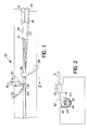
- Fig. 1 shows a portion of a cigarette making machine 10 generally referred to as the garniture.
- Fig. 2 shows a sectional view of the portion containing the novel paste nozzle according to the invention.
- the exemplary cigarette making machine 10 may be generally as shown and described in U.S. patent No. 3,105,498.
- a continuous tobacco rod 12 and wrapping paper 14 are moved along machine 10 (in the direction toward the left) in a groove 15 formed by a pair of converging guides 16, 18.
- the bottom of the groove 15 is arcuate shape and the guides 16, 18 act to gradually fold the paper 14 in a circular shape about the tobacco rod 12.
- a tongue 22 is provided to isolate the tobacco from the overhanging paper in the initial stages as it is folded.
- the guides 16, 18 expose one edge, or lap 24, in an upright position, such that paste can be applied.
- the ends of the paper 14 are folded about the tobacco rod 12 with the adhesive on lap 24 sealing the ends of the paper together.
- the foregoing type of garniture with the exception of the novel paste applicator system of the present invention (described below), is well known, and any type of suitable garniture may be used with the present invention.
- a paste nozzle assembly 30 which receives starch paste through a feed line 31, is mounted on machine 10, and positioned such that the paste nozzle 32 is directed at the inside surface of the exposed lap 24 of paper 14.
- the nozzle 32 is positioned so that the tip is in contact with the paper.
- a compressed air nozzle 34 supplied through air line 35, is directed at the paste nozzle 32.
- one or more dust hoods 36 are positioned up line of the paste nozzle 32 for removing loose tobacco through a suction line 38.
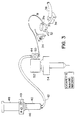
- Paste pot 40 may be the same as the known paste pot assemblies used with the Molins Mark IX, in which one end includes a moveable piston plate 46.
- a pneumatic ram 48 presses against the piston plate 46 to push paste out through supply line 42.
- the ram includes appropriate controls 49 for varying ram pressure and for retracting the ram (in order to change paste pots).
- the supply line 42 is preferably connected to the paste pot by a quick connect coupling to facilitate changing paste pots.
- Metering pump 44 is preferably a high precision spinning pump having an output proportional to speed, such as Feinpruf model SPSO582AAZ,N19 having a capacity of 0.6 cc/rev.
- the pump is provided with a manual feed wheel 50, which is used to bleed air from the paste line when paste pots are changed.
- Metering pump 44 is driven by a gear reducer 52, which is connected to a gear drive 54.
- a gear reducer such as Browning model SM133C1 may be used.
- Gear drive 54 is connected to the drive of the cigarette making machine, as indicated schematically, so as to have a rotational speed proportional to the speed of the maker, i.e. proportional to the speed of the moving cigarette paper and tobacco rod. Any suitable gear, pulley, chain or other connection may be used.
- Existing Molins Mark IX equipment has a gear drive, and such may be used in the present invention to drive the gear reducer 52.
- a mounting block 60 includes a pair of holes 62, which may be used to attach the block 60 to the garniture 10, and a threaded hole 64 for securing the upper part of the assembly.
- the upper face of the block 60 includes guides 66 for seating a nozzle housing 68, described further below.
- Nozzle housing 68 is secured to the mounting block 60 by a knurled fastener 70, the threaded shaft of which extends through a bore 72 in the nozzle housing 68 and is screwed into the threaded hole 64 in the mounting block. This permits the nozzle housing to be removed easily when desired, and to be re-mounted precisely in position.
- the nozzle housing 68 which is preferably brass, includes, in addition to bore 72, a threaded intake hole 74 and a threaded nozzle mounting hole 76.
- the intake hole 74 and nozzle mounting hole 76 communication with one another in the region indicated 80.
- the holes 74, 76 are laterally offset from one another, since they are oriented at different angles, and this also allows room for bore 72.
- the bottom of the housing 68 includes laterally opposed cutouts, that cooperate with the seating guides 66 in the mounting block 60.
- Hole 74 is threaded so as to receive a threaded coupling 31a from the metering pump supply line 31, whereas the hole 76 is threaded to receive the threaded end of the nozzle.
- the hole 76 is angled down about 6° relative to horizontal to point the nozzle down. The purpose of this is to match the angle of the paper, which in the Molins Mark IX machine is at a slight angle to vertical. By orienting the nozzle in this manner, the tip of the nozzle is perpendicular to the paper. If used in equipment where the lap is a different angle, the angle of the nozzle should be adjusted accordingly so that the nozzle tip remains perpendicular to the paper. Also, as shown in Fig.
- the nozzle hole 76 is not exactly perpendicular to the direction of paper travel, but rather is angled about 6° - 7° back away from the direction of paper travel, i.e., so as to lie at about 83° to 84° relative to the direction of paper travel, which has been found to improve the application of paste.
- a pencil paster nozzle 32 preferably is made of stainless steel and includes a threaded end 80, which is screwed into the nozzle mounting hole 76.
- the dimensions of the nozzle bore are selected so that the paste flows from the nozzle at relatively low pressure, at a flow rate that will maintain a continuous film on the paper.
- the cross-sectional flow area through the nozzle bore is sufficient so that the paste flows from the nozzle at a relatively low velocity, to allow the nozzle to remain in contact with the paper.
- the threaded end 80 and nozzle tube 82 include a 5/65" bore 84 therethrough, except that at the outer end of the nozzle tube 82 the bore is enlarged to 7/64" for a distance of 1/4" from the tip.
- a nozzle tip 86 which has an outside diameter matching the enlarged end bore 88 of tube 82 (i.e. 7/64"), is press fit into the enlarged end bore 88.
- the tip 86 includes an internal bore 90 therethrough of the same diameter as the tube bore 84, i.e. 5/64".
- opposite sides 92 of the nozzle tube 82 have flats 89, to permit the use of a wrench when tightening the nozzle assembly in the hole 76.
- the tip Prior to using the nozzle, it has been found preferable to squeeze the tip to make it oblong, e.g. with a dimension of 3.8 mm x 2.0 mm, with the longer dimension oriented perpendicular to the direction of paper travel. By thus elongating the nozzle tip, it has been found that a more uniform application of paste is achieved than in the case of a round tip.
- the tip 86 of the nozzle 32 is initially polished in the direction of paper traveling using crocus cloth TR3. The purpose of this is to remove small grooves through which leakage could occur.
- the threaded end 80 of the nozzle 32 is then screwed into the nozzle housing 68, together with the supply line connector 31a.
- the longer dimension of the oblong nozzle tip should be positioned vertically, perpendicular to the direction of paper travel.
- the housing 68 is positioned on the mounting block 60 and secured in place by the knurled fastener 70.
- a paste pot 40 is installed in the pneumatic ram assembly and the ram is actuated.
- the manual feed wheel on the metering pump 44 is then turned to feed paste to the nozzle 32 until such time as air is removed from the supply lines.
- the cigarette making machine can be started, and paste will be supplied by the metering pump 44, at the appropriate rate depending on machine speed.
- the characteristics of the metering pump, gear reducer, pneumatic ram, and nozzle are selected so that paste flows out of the nozzle tip at a relatively low pressure, at a rate (speed dependent) at which it will form a thin uniform film on the paper.
- the pneumatic ram pressure is set to ensure a sufficient flow of paste to the metering pump. If, due to batch-to-batch variance in paste consistency, insufficient paste is delivered to the pump, the ram pneumatic pressure is increased to compensate.
Landscapes
- Manufacturing Of Cigar And Cigarette Tobacco (AREA)
Claims (8)
- Vorrichtung zum Aufbringen von Stärkekleister bzw. -leim auf eine(n) frei liegende(n) bzw. exponierte(n) Rand bzw. Kante von bewegtem Zigarettenpapier, umfassend eine Kleisterdüse (30, 32) mit einer Außenspitze (86), die so angeordnet ist, daß ein Abschnitt davon mit dem freiliegenden Rand des Zigarettenpapiers in Kontakt steht, um entlang des Randes Kleister aufzubringen, sowie Mittel (40, 44) zum Zuführen von Kleister mit geregelter Geschwindigkeit bzw. Menge und unter geregeltem Druck zur Düse, dadurch gekennzeichnet, daß das Mittel (40, 44) eine Hochpräzisionsdosierpumpe (44) zum Zuführen von Kleister mit geregelter Geschwindigkeit bzw. Menge zur Düse (30, 32) und Mittel (40) zum Zuführen von Stärkekleister unter geregeltem Druck zur Hochpräzisionsdosierpumpe (44) umfaßt, und dadurch, daß die Düse (30, 32) eine Innenbohrung (84, 90) mit einer solchen Größe aufweist, daß Kleister unter relativ geringem Druck und mit einer solchen Geschwindigkeit bzw. Menge abgegeben wird, daß ein dünner, gleichmäßiger Kleisterfilm auf den Rand bzw. die Kante aufgebracht wird, während sich das Papier an der Spitze (86) vorbeibewegt, und dadurch, daß die Spitze (86) einen länglichen Querschnitt aufweist und so ausgerichtet ist, daß die längere Abmessung im wesentlichen senkrecht zur Richtung der Papierbewegung verläuft.
- Vorrichtung nach Anspruch 1, worin die Düse ein Düsenrohr umfaßt, worin die Außenspitze eine im Düsenrohr angeordnete Düsenspitze umfaßt und worin die Innenbohrung durch das Düsenrohr und die Düsenspitze den gleichen Durchmesser aufweisen.
- Vorrichtung nach Anspruch 1 oder 2, worin jener Abschnitt der Spitze (86), der so angeordnet ist, daß er mit dem Papier in Kontakt steht, in Papierbewegungsrichtung poliert wurde.
- Vorrichtung nach einem der vorangegangenen Ansprüche, worin die Achse der Spitzenbohrung in einem Winkel von 83° bis 84° relativ zur Papierbewegungsrichtung ausgerichtet ist.
- Hochgeschwindigkeitsmaschine (10) zum Falten und Abdichten einer kontinuierlichen Länge von Zigarettenpapier (14) um einen Tabakstab (12) herum, umfassend eine Vorrichtung nach einem der vorangegangenen Ansprüche und einen Besatz zur Freilegung eines Randes bzw. einer Kante des Papiers, um eine Überlappung bzw. Lage bzw. Wickel (24) zu definieren, worin die Düsenspitze (86) so angeordnet ist, daß sie mit der Überlappung (24) in Kontakt steht, um Stärkekleister darauf aufzubringen.
- Maschine (10) nach Anspruch 5, worin die Dosierpumpe (44) eine Hochpräzisionsrotationspumpe umfaßt, und welche Maschine Mittel (52, 54) zum Koppeln der Rotationsgeschwindigkeit der Pumpe an die Bewegungsgeschwindigkeit von Papier an der Düse vorbei umfaßt.
- Maschine (10) nach Anspruch 5 oder 6, die Mittel zum Variieren der Betriebsgeschwindigkeit umfaßt, worin die Dosierpumpe (44) zur Düse (30, 32) Kleister mit einer Geschwindigkeit zuführt, die proportional zur Betriebsgeschwindigkeit der Maschine ist.
- Maschine nach einem der Ansprüche 5 bis 7, umfassend ein Düsengehäuse (68) zum Aufnehmen der Düse und einen Montageblock (60) auf der Maschine (10), um das Düsengehäuse (68) abnehmbar zu montieren.
Applications Claiming Priority (3)
| Application Number | Priority Date | Filing Date | Title |
|---|---|---|---|
| US55813890A | 1990-07-25 | 1990-07-25 | |
| US558138 | 1990-07-25 | ||
| PCT/US1991/005235 WO1992001395A1 (en) | 1990-07-25 | 1991-07-24 | Apparatus for applying starch paste to tobacco articles |
Publications (2)
| Publication Number | Publication Date |
|---|---|
| EP0497936A1 EP0497936A1 (de) | 1992-08-12 |
| EP0497936B1 true EP0497936B1 (de) | 1996-09-25 |
Family
ID=24228374
Family Applications (1)
| Application Number | Title | Priority Date | Filing Date |
|---|---|---|---|
| EP91913836A Expired - Lifetime EP0497936B1 (de) | 1990-07-25 | 1991-07-24 | Einrichtung zum aufbringen von stärkeleim auf tabakwaren |
Country Status (4)
| Country | Link |
|---|---|
| US (1) | US5345950A (de) |
| EP (1) | EP0497936B1 (de) |
| DE (1) | DE69122373T2 (de) |
| WO (1) | WO1992001395A1 (de) |
Cited By (1)
| Publication number | Priority date | Publication date | Assignee | Title |
|---|---|---|---|---|
| CN104138030A (zh) * | 2013-05-07 | 2014-11-12 | 豪尼机械制造股份公司 | 用于将胶水印痕涂覆到烟草加工业的棒状制品的包覆条上的装置 |
Families Citing this family (18)
| Publication number | Priority date | Publication date | Assignee | Title |
|---|---|---|---|---|
| DE4437631A1 (de) * | 1994-10-21 | 1996-04-25 | Decoufle Sarl | Vorrichtung zum Erwärmen der Klebnaht eines Stranges der tabakverarbeitenden Industrie |
| DE19719000A1 (de) | 1997-05-06 | 1998-11-12 | Focke & Co | Verfahren und Vorrichtung zum Aufbringen von Leim auf Zuschnitte für Packungen |
| JP4033399B2 (ja) * | 2001-06-08 | 2008-01-16 | 日本たばこ産業株式会社 | フィルタ装着装置 |
| DE50303937D1 (de) | 2003-01-31 | 2006-08-03 | Hauni Maschinenbau Ag | Verfahren zum Beleimen einer bewegten Bahn, sowie Vorrichtung, insbesondere zur Durchführung des Verfahrens |
| GB0310034D0 (en) * | 2003-04-30 | 2003-06-04 | British American Tobacco Co | Improvements relating to material application to rod wrappers |
| US8925556B2 (en) | 2006-03-31 | 2015-01-06 | Philip Morris Usa Inc. | Banded papers, smoking articles and methods |
| DE102009009830A1 (de) * | 2009-02-18 | 2010-08-26 | Hauni Maschinenbau Ag | Einstelleinrichtung mit mindestens einer Leimdüse für Strangmaschinen der Tabak verarbeitenden Industrie sowie Strangmaschine mit einer solchen Einstelleinrichtung |
| US8701682B2 (en) | 2009-07-30 | 2014-04-22 | Philip Morris Usa Inc. | Banded paper, smoking article and method |
| CN101897470A (zh) * | 2010-08-06 | 2010-12-01 | 安徽中烟工业公司 | 膨胀烟丝的回潮方法 |
| US11707082B2 (en) | 2010-12-13 | 2023-07-25 | Altria Client Services Llc | Process of preparing printing solution and making patterned cigarette wrapper |
| US9302522B2 (en) | 2010-12-13 | 2016-04-05 | Altria Client Services Llc | Process of preparing printing solution and making patterned cigarette wrappers |
| DE102011015350A1 (de) * | 2011-03-28 | 2012-10-04 | Hauni Maschinenbau Ag | Vorrichtung zum Beleimen eines bewegten Umhüllungsstreifens für stabförmige Produkte der Tabak verarbeitenden Industrie und Anlage mit einer derartigen Vorrichtung |
| JP6091494B2 (ja) | 2011-05-16 | 2017-03-08 | アルトリア クライアント サービシーズ エルエルシー | シガレット包装具の交互パターン、喫煙物品、及び方法 |
| EP2849585B1 (de) | 2012-05-16 | 2022-02-23 | Altria Client Services LLC | Neuartiges gebändertes zigarettenpapier mit bändern mit geöffneten bereichen |
| CA2873540A1 (en) | 2012-05-16 | 2013-11-21 | Altria Client Services Inc. | Cigarette wrapper with novel pattern |
| US11064729B2 (en) | 2012-05-16 | 2021-07-20 | Altria Client Services Llc | Cigarette wrapper with novel pattern |
| CN103876276B (zh) * | 2014-03-14 | 2017-01-11 | 河南中烟工业有限责任公司 | 一种可调控风味的卷烟加香方法 |
| EP4233577A4 (de) * | 2020-10-20 | 2024-09-11 | Japan Tobacco Inc. | Geschmacksinhalator und geschmacksinhalationssystem |
Family Cites Families (20)
| Publication number | Priority date | Publication date | Assignee | Title |
|---|---|---|---|---|
| US1992736A (en) * | 1934-03-23 | 1935-02-26 | American Mach & Foundry | Cigarette machine paster |
| US2130689A (en) * | 1935-03-05 | 1938-09-20 | American Mach & Foundry | Paste-applying device for cigarette machines |
| US2579967A (en) * | 1946-07-30 | 1951-12-25 | Molins Machine Co Ltd | Device for applying adhesive to a traveling surface |
| US2660177A (en) * | 1948-02-17 | 1953-11-24 | Usines Deeoufle Sa | Automatic tobacco feeding cigarette machine |
| FR1007040A (fr) * | 1948-02-17 | 1952-04-30 | Decoufle Usines | Perfectionnement à la formation du boudin de tabac dans la machine à cigarettes à boudin continu |
| US2606521A (en) * | 1950-03-10 | 1952-08-12 | American Tobacco Co | Adhesive applying apparatus for cigarette making machines |
| BE572389A (de) * | 1954-01-07 | |||
| NL298514A (de) * | 1956-12-18 | |||
| US3030966A (en) * | 1956-12-18 | 1962-04-24 | Decoufle Usines | Filler forming mechanism |
| FR1167113A (fr) * | 1957-01-11 | 1958-11-20 | Decoufle Usines | Perfectionnement aux machines à confectionner des cigarettes |
| US3088468A (en) * | 1958-01-21 | 1963-05-07 | Molins Machine Co Ltd | Tobacco manipulating machinery |
| GB927927A (en) * | 1959-12-15 | 1963-06-06 | Desmond Walter Molins | Improvements in or relating to the manufacture of cigarettes |
| GB907706A (en) * | 1960-01-27 | 1962-10-10 | Molins Machine Co Ltd | Improvements in cigarette-making machines |
| FR1422045A (fr) * | 1964-03-17 | 1965-12-24 | Molins Machine Co Ltd | Dispositif d'alimentation pour amener des pâtes ou liquides à leur point d'utilisation |
| US3548836A (en) * | 1966-11-09 | 1970-12-22 | Gen Cigar Co | Apparatus for reinforcing the head end of a cigar |
| GB1318188A (en) * | 1969-08-04 | 1973-05-23 | Molins Machine Co Ltd | Apparatus for delivering paste and the like |
| DE2634548A1 (de) * | 1976-07-31 | 1978-02-02 | Hauni Werke Koerber & Co Kg | Leimentgasungsvorrichtung |
| DE3534454A1 (de) * | 1985-09-27 | 1987-04-02 | Hauni Werke Koerber & Co Kg | Verfahren und vorrichtung zum beleimen von bewegten umhuellungsstreifen der tabakverarbeitenden industrie |
| DE8803131U1 (de) * | 1988-03-08 | 1988-04-21 | Nordson Corp., Westlake, Ohio | Vorrichtung zum Auftragen von tierischen oder pflanzlichen Leimen auf ein Substrat |
| US5056462A (en) * | 1989-11-27 | 1991-10-15 | Nordson Corporation | Coating system with correction for non-linear dispensing characteristics |
-
1991
- 1991-07-24 DE DE69122373T patent/DE69122373T2/de not_active Expired - Fee Related
- 1991-07-24 WO PCT/US1991/005235 patent/WO1992001395A1/en not_active Ceased
- 1991-07-24 EP EP91913836A patent/EP0497936B1/de not_active Expired - Lifetime
-
1993
- 1993-02-12 US US08/017,981 patent/US5345950A/en not_active Expired - Fee Related
Cited By (1)
| Publication number | Priority date | Publication date | Assignee | Title |
|---|---|---|---|---|
| CN104138030A (zh) * | 2013-05-07 | 2014-11-12 | 豪尼机械制造股份公司 | 用于将胶水印痕涂覆到烟草加工业的棒状制品的包覆条上的装置 |
Also Published As
| Publication number | Publication date |
|---|---|
| EP0497936A1 (de) | 1992-08-12 |
| WO1992001395A1 (en) | 1992-02-06 |
| DE69122373D1 (de) | 1996-10-31 |
| US5345950A (en) | 1994-09-13 |
| DE69122373T2 (de) | 1997-02-27 |
Similar Documents
| Publication | Publication Date | Title |
|---|---|---|
| US5345950A (en) | Apparatus for applying starch paste to tobacco articles | |
| US4735169A (en) | Adhesive applicator assembly | |
| US4119058A (en) | Glue applicators | |
| US4048950A (en) | Devices for applying adhesives to a moving web | |
| JPH0575599B2 (de) | ||
| EA001987B1 (ru) | Сопло | |
| US5221350A (en) | Gumming device for a strip of paper | |
| KR101140427B1 (ko) | 막대부 형성기계 및 막대부 형성방법 | |
| EP0064340A1 (de) | Klebstoffauftragsystem für eine Maschine zum Zusammenstellen von Bahnen | |
| JPS58156365A (ja) | 移動する材料帯へ糊を筋状に塗布する装置 | |
| GB2074097A (en) | Supplying ink to a web-printing machine | |
| US4704308A (en) | Method and apparatus for maintaining a glue applicator ready for operation | |
| US5531233A (en) | Method of and apparatus for applying adhesive to cigarette paper and the paper and cigarette produced thereby | |
| SU1118277A3 (ru) | Устройство дл прерывистого нанесени кле | |
| US2919673A (en) | Positioning control means for web striping device | |
| CN100404143C (zh) | 将粘结剂涂敷于移动幅面的方法及实施该方法的装置 | |
| JPH0429779B2 (de) | ||
| CN113304952A (zh) | 一种烟用滤棒包装纸带中线胶涂覆装置及方法 | |
| US6932870B2 (en) | System and process for dispensing an adhesive onto a core during the formation of rolled products | |
| CN215918000U (zh) | 一种上胶机构 | |
| EP1219540B1 (de) | Verfahren, Gerät und Anlage zum Gummieren von Gegenständen | |
| DE2452138C2 (de) | Vorrichtung zum beleimen eines endlosen umhuellungsstreifens auf strangmaschinen der tabakverarbeitenden industrie | |
| US3377001A (en) | Metering and dispensing device for viscous liquids | |
| EP1069045A1 (de) | Vorrichtung zum Zuführen von Klebstoff zu Ausgabeköpfen | |
| CN224041440U (zh) | 一种纸板涂胶装置 |
Legal Events
| Date | Code | Title | Description |
|---|---|---|---|
| PUAI | Public reference made under article 153(3) epc to a published international application that has entered the european phase |
Free format text: ORIGINAL CODE: 0009012 |
|
| 17P | Request for examination filed |
Effective date: 19920413 |
|
| AK | Designated contracting states |
Kind code of ref document: A1 Designated state(s): AT BE CH DE DK ES FR GB GR IT LI LU NL SE |
|
| 17Q | First examination report despatched |
Effective date: 19931116 |
|
| GRAH | Despatch of communication of intention to grant a patent |
Free format text: ORIGINAL CODE: EPIDOS IGRA |
|
| GRAH | Despatch of communication of intention to grant a patent |
Free format text: ORIGINAL CODE: EPIDOS IGRA |
|
| RBV | Designated contracting states (corrected) |
Designated state(s): DE FR GB IT |
|
| GRAA | (expected) grant |
Free format text: ORIGINAL CODE: 0009210 |
|
| AK | Designated contracting states |
Kind code of ref document: B1 Designated state(s): DE FR GB IT |
|
| REF | Corresponds to: |
Ref document number: 69122373 Country of ref document: DE Date of ref document: 19961031 |
|
| ET | Fr: translation filed | ||
| ITF | It: translation for a ep patent filed | ||
| PLBE | No opposition filed within time limit |
Free format text: ORIGINAL CODE: 0009261 |
|
| STAA | Information on the status of an ep patent application or granted ep patent |
Free format text: STATUS: NO OPPOSITION FILED WITHIN TIME LIMIT |
|
| 26N | No opposition filed | ||
| REG | Reference to a national code |
Ref country code: GB Ref legal event code: IF02 |
|
| PGFP | Annual fee paid to national office [announced via postgrant information from national office to epo] |
Ref country code: GB Payment date: 20020712 Year of fee payment: 12 |
|
| PGFP | Annual fee paid to national office [announced via postgrant information from national office to epo] |
Ref country code: FR Payment date: 20020723 Year of fee payment: 12 |
|
| PGFP | Annual fee paid to national office [announced via postgrant information from national office to epo] |
Ref country code: DE Payment date: 20020727 Year of fee payment: 12 |
|
| PG25 | Lapsed in a contracting state [announced via postgrant information from national office to epo] |
Ref country code: GB Free format text: LAPSE BECAUSE OF NON-PAYMENT OF DUE FEES Effective date: 20030724 |
|
| PG25 | Lapsed in a contracting state [announced via postgrant information from national office to epo] |
Ref country code: DE Free format text: LAPSE BECAUSE OF NON-PAYMENT OF DUE FEES Effective date: 20040203 |
|
| GBPC | Gb: european patent ceased through non-payment of renewal fee |
Effective date: 20030724 |
|
| PG25 | Lapsed in a contracting state [announced via postgrant information from national office to epo] |
Ref country code: FR Free format text: LAPSE BECAUSE OF NON-PAYMENT OF DUE FEES Effective date: 20040331 |
|
| REG | Reference to a national code |
Ref country code: FR Ref legal event code: ST |
|
| PG25 | Lapsed in a contracting state [announced via postgrant information from national office to epo] |
Ref country code: IT Free format text: LAPSE BECAUSE OF NON-PAYMENT OF DUE FEES Effective date: 20050724 |