EP0497996B1 - Appareil pour le traitement indirect, utilisant l'effet corona, de matériaux conducteurs et non conducteurs de differentes formes et épaisseurs - Google Patents
Appareil pour le traitement indirect, utilisant l'effet corona, de matériaux conducteurs et non conducteurs de differentes formes et épaisseurs Download PDFInfo
- Publication number
- EP0497996B1 EP0497996B1 EP91101411A EP91101411A EP0497996B1 EP 0497996 B1 EP0497996 B1 EP 0497996B1 EP 91101411 A EP91101411 A EP 91101411A EP 91101411 A EP91101411 A EP 91101411A EP 0497996 B1 EP0497996 B1 EP 0497996B1
- Authority
- EP
- European Patent Office
- Prior art keywords
- electrode
- electrodes
- pin
- treated
- discharge
- Prior art date
- Legal status (The legal status is an assumption and is not a legal conclusion. Google has not performed a legal analysis and makes no representation as to the accuracy of the status listed.)
- Expired - Lifetime
Links
Images





Classifications
-
- B—PERFORMING OPERATIONS; TRANSPORTING
- B29—WORKING OF PLASTICS; WORKING OF SUBSTANCES IN A PLASTIC STATE IN GENERAL
- B29C—SHAPING OR JOINING OF PLASTICS; SHAPING OF MATERIAL IN A PLASTIC STATE, NOT OTHERWISE PROVIDED FOR; AFTER-TREATMENT OF THE SHAPED PRODUCTS, e.g. REPAIRING
- B29C59/00—Surface shaping of articles, e.g. embossing; Apparatus therefor
- B29C59/10—Surface shaping of articles, e.g. embossing; Apparatus therefor by electric discharge treatment
- B29C59/106—Surface shaping of articles, e.g. embossing; Apparatus therefor by electric discharge treatment the electrodes being placed on the same side of the material to be treated
-
- H—ELECTRICITY
- H01—ELECTRIC ELEMENTS
- H01T—SPARK GAPS; OVERVOLTAGE ARRESTERS USING SPARK GAPS; SPARKING PLUGS; CORONA DEVICES; GENERATING IONS TO BE INTRODUCED INTO NON-ENCLOSED GASES
- H01T19/00—Devices providing for corona discharge
- H01T19/04—Devices providing for corona discharge having pointed electrodes
Definitions
- the invention relates to a device according to the preamble of claim 1.
- Devices for treating the surface of webs of plastic or other materials by uniformly distributed electrical discharges on the surface to be treated with two working electrodes, one of which is coated with a dielectric material (FIG. 1).
- a high alternating voltage with a frequency is typically between the two electrodes 1o kHz and 100 kHz placed so that a uniform spark discharge takes place.
- the material to be treated is passed between the electrodes and subjected to the discharge.
- the electrode systems typically have distances in the millimeter range between 1 and 3 mm. Therefore, the treatment with such devices is limited to flat or one-sided curved thin substrates such as plastic films and papers.
- the dielectric burns due to the permanent stresses caused by electrical discharges and is therefore unusable.
- a further disadvantage is parasitic corona discharges on the back of the webs, since these do not lie fully on the electrode designed as a roller, particularly at higher speeds.
- the limitation to thin materials is also a major disadvantage in practice.
- the treatment is for thicker materials no longer possible because the total electrical resistance between the electrodes becomes so great that a perfect corona discharge no longer ignites. It may also happen that thick material can no longer withstand the high discharge voltage then required, so that there are individual electrical breakdowns which damage the material to be treated. This is particularly the case with porous, inhomogeneous materials such as foam.
- a device which is constructed as defined in the preamble of claim 1 is known from DE-OS 26 09 783. With this device, a backside treatment of the film to be treated is basically avoided. At the same time, the electrostatic charge on the film is reduced by the corona treatment. In practice, however, such devices have often not proven successful. Either the arrangement is not sufficient to provide intensive pretreatment with good efficiency, or the arrangement heats up disproportionately, which results in a short service life, or a large amount of gas is required to operate the device with a short distance from it Substrate.
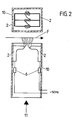
- Another known construction consists of a short, rectangular plastic tube, at one end of which, on two opposite sides, a larger number of individual knife electrodes form two electrode packs which are arranged at a short distance from one another (see FIG. 2).
- each knife package is connected to a 50 Hz high-voltage source via a series resistor, which is housed in the tube.
- the individual sparks between the pair of knives are deflected outwards with a powerful, non-directional air flow. Leave with such a device the surfaces of almost arbitrarily shaped materials and also those of thicker materials are treated on one side.
- the advantage lies in the fact that the electrical sparks deflected by the gas flow enable treatment even at a distance of several millimeters.
- the parallel knives lie within the two electrode knife packages at a common electrical potential.
- Several ignition sparks are therefore formed between the packets, but these jump back and forth between directly or diagonally opposite knives and have different energies and their range changes randomly.
- the jumping back and forth of the sparks is further favored by the low frequency of 50 Hz, since the spark channels that form open again and again due to the air flow, i.e. to be interrupted.
- the undirected, swirling gas flow further promotes these spinning and oscillating movements of the discharge sparks.
- the invention has for its object to provide a device of the type mentioned, through which a uniform, intensive corona treatment of materials of any type, shape and thickness is possible without generating an electric field reaching through the material. Furthermore, the invention is concerned with the problem of completely avoiding corona effects on the back of the material to be treated, largely preventing the electrostatic charging of the material, not having to use a counter electrode of any kind, and in particular not having to arrange any dielectric material in the discharge gap.
- the metallic pin electrodes either carry voltage or one is connected to voltage and the other is connected to ground, ie it is grounded.
- the current-limiting component such as a resistor, a varistor or a capacitor
- Capacitors are preferably used for this.
- the capacitors take on the task of the dielectric. By selecting the capacitors with the appropriate capacitance, the desired voltage can be set and the generator electrically connected to the treatment electrode be adjusted. The treatment effect is fundamentally very intense.
- the device according to the invention now has a double pin electrode, i.e. a pair of pin electrodes, with a separate channel for pressurization being provided for each pin electrode. It has surprisingly been found that if such a separate channel is provided for each of the pin electrodes, a particularly stable and intense, arc-shaped discharge channel is produced which, in terms of the desired surface treatment, shows a better result than is known from known devices with a common one Channel for both pin electrodes is the case.
- the spark intensity and thus the treatment effect understandably also depends on the electrical power, the gas flow and the type of gas used.
- the device can be designed as specified in claim 2.
- Several units or elements, each with a pair of electrodes and a channel for gas admission, can be combined as required for the treatment result.
- the same basic unit, consisting of an electrode holder, a pair of pin electrodes and a gas admission channel, can always be used.
- a device of this type with a plurality of pin electrode pairs arranged next to one another, it is possible to switch off individual electrode pairs by arranging corresponding switches and thus to influence the treatment pattern. This switch-off is possible on the electrode, but also from a remote control device.
- gases can be used. By selecting appropriate gases, it is not only possible to To influence surface treatment, but also to carry out a material application.
- suitable gases or aerosols are used, which become reactive due to the chemical and physical processes taking place in the spark area and which separate on the workpiece.
- gases are, for example, all hydrocarbons and related compounds which, for example, additionally contain fluorine, silicon or metal atoms, or also silane.
- the device shown in FIG. 1 and belonging to the prior art consists of a transformer or generator 1, a working electrode 2, the working gap 3 and the roller 5 with dielectric 4 forming the counter electrode.
- the film web to be treated is designated by F. It can be clearly seen that the discharge takes place through the dielectric 4.
- the device shown in FIG. 2 has two knife electrode packs 2, which are arranged at the end of a plastic tube 10.
- the pressurized gas is supplied at 11.
- the film to be treated is again designated F.
- 3A and 3B show the essential components of the device according to the invention, different electrical switching options being shown in FIG. 9.
- the device consists of a base body 15 made of ceramic material, in which the two pin electrodes 12 made of metal, preferably made of tungsten, are arranged. It is about bare pin electrodes without any dielectric. The pin electrodes are inclined so that the discharge ends are at the smallest distance, so that the spark is safely ignited and the desired corona discharge takes place.
- a channel 17 is formed for pressurizing gas by a gas stream 11.
- a current-limiting element 13 or 14 - a capacitor is shown as an example - is interposed. The capacitors practically do the job of the dielectric.
- the channels 17a are supplied by the channel 17 connected upstream in the flow direction.
- the secondary winding of transformer 1 outputs a voltage between 2 and 10 kV.
- the mouth region of the electrode holder 15, into which the channel 17 for pressurized gas discharge, is adapted to the pin geometry.
- the working distance s depends on the angle that the electrode pins form with one another. At an angle of 20 °, the usable maximum working distance s is approximately 20 mm.
- FIG. 8 An electrode holder 15 designed as a tube is shown in FIG. 8, the high-voltage and gas supply being effected via the correspondingly designed supply hose 19.
- the corona arch is labeled K.
- the film F to be treated is moved in the direction of the arrow shown.
- FIG. 9 four different circuit options are shown using the example of the use of a capacitor as a current-limiting element.
- the capacitor 14 is missing, since one-sided grounding was carried out at 16 here.
- One electrode 12 is therefore directly connected to ground.
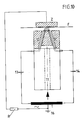
- the embodiment according to FIG. 10 shows an additional electrode Z on the back of the film to be treated.
- the additional electrode can be, for example, a metallic roller over which the film F runs.
- the secondary coil of the transformer is then expediently grounded in the center.
- the mass reference 16 can then be omitted.
- the series resistor R or thyristor or capacitor is optionally switched on.
- an auxiliary electrode H can be provided, as shown in FIG. 11. This is supplied with voltage via a series resistor R.
- FIG. 12 shows the arrangement of several pairs of pin electrodes, each with an associated channel 17 for pressurizing gas. Since the treatment width of a pair of pin electrodes is in the millimeter range, treatments of any width can be carried out if corresponding pin electrode pairs are arranged next to one another. The result is a closed, treated surface of appropriate width.
- the pairs of electrodes can be arranged such that their discharge ends lie one behind the other or next to one another with respect to the direction of movement of the film F.
- the individual elements can also be combined in such a way that two (or more) rows of pin electrode pairs arranged one behind the other are formed, and that the rows are offset from one another.
- a further embodiment is shown in FIG. 12, namely the use of mechanical or magnetic switches 18, which are expediently installed behind the corresponding capacitor 14, since the voltage is lower here. This makes it possible to set the working width by switching individual electrode pin pairs on and off and to leave individual tracks on the web untreated.
- FIG. 13 An embodiment is shown in which an additional channel 27 for supplying a reactive gas is provided directly to the discharge arc.
Landscapes
- Physics & Mathematics (AREA)
- Engineering & Computer Science (AREA)
- Plasma & Fusion (AREA)
- Treatments Of Macromolecular Shaped Articles (AREA)
- Physical Or Chemical Processes And Apparatus (AREA)
- Elimination Of Static Electricity (AREA)
Claims (7)
- Dispositif pour le traitement indirect de l'effet de couronne de matériaux conducteurs et non conducteurs (F), par exemple de feuilles continues en matière plastique, en papier, métal et/ou tissu, ou de corps moulés en ces matériaux pour augmenter l'énergie superficielle avec deux électrodes métalliques à pointe (12), entre lesquelles a lieu la décharge, qui sont placées sur le même côté du matériau (F) qui doit être pré-traité et qui est déplacé par rapport à elles et dont l'entrefer de décharge est chargé en gaz comprimé en direction de la surface à traiter, et avec un transformateur (1) qui fournit la tension alternative électrique, caractérisé en ce que la paire d'électrodes à pointe (12) est placée dans un porte-électrodes (15) en matériau isolant, de préférence en céramique, dans lequel un canal propre (17a) est configuré pour chaque électrode à pointe (12) pour l'impact de gaz comprimé.
- Dispositif selon la revendication 1, caractérisé en ce que plusieurs paires d'électrodes (12) ou porte-électrodes (15) avec une paire d'électrodes (12) sont placés l'un à côté de l'autre, les extrémités de décharge de chacune des paires d'électrodes à pointe pouvant être placées par rapport au sens de déplacement de la surface à traiter aussi bien derrière les unes les autres qu'à côté les unes des autres.
- Dispositif selon la revendication 2, caractérisé en ce que des paires d'électrodes à pointe séparées (12) peuvent être déconnectées.
- Dispositif selon la revendication 3, caractérisé en ce que les commutateurs (18) sont placés derrière l'élément limiteur de courant, comme par exemple le condensateur (13 ou 14).
- Dispositif selon l'une ou plusieurs des revendications précédentes, caractérisé en ce qu'il est prévu une électrode supplémentaire (Z) pour renforcer l'effet de traitement au dos du matériau à traiter (feuille F) (figure 10).
- Dispositif selon l'une ou plusieurs des revendications précédentes, caractérisé en ce qu'une électrode auxiliaire (H) est placée entre les électrodes à pointe (12) pour améliorer l'effet d'amorçage, électrode qui peut être chargée de tension par une résistance série (R) (figure 11).
- Dispositif selon l'une ou plusieurs des revendications précédentes, caractérisé en ce que le dispositif est pourvu d'un canal supplémentaire (27) pour l'impact de gaz comprimé avec lequel un gaz réactif peut être amené directement à l'arc de décharge (figure 13).
Priority Applications (4)
| Application Number | Priority Date | Filing Date | Title |
|---|---|---|---|
| AT91101411T ATE104206T1 (de) | 1991-02-02 | 1991-02-02 | Vorrichtung zur indirekten koronabehandlung von leitenden und nichtleitenden materialien unterschiedlichster gestalt und dicke. |
| DK91101411.6T DK0497996T3 (da) | 1991-02-02 | 1991-02-02 | Koronabehandling af materialer |
| DE59101384T DE59101384D1 (de) | 1991-02-02 | 1991-02-02 | Vorrichtung zur indirekten Koronabehandlung von leitenden und nichtleitenden Materialien unterschiedlichster Gestalt und Dicke. |
| EP91101411A EP0497996B1 (fr) | 1991-02-02 | 1991-02-02 | Appareil pour le traitement indirect, utilisant l'effet corona, de matériaux conducteurs et non conducteurs de differentes formes et épaisseurs |
Applications Claiming Priority (1)
| Application Number | Priority Date | Filing Date | Title |
|---|---|---|---|
| EP91101411A EP0497996B1 (fr) | 1991-02-02 | 1991-02-02 | Appareil pour le traitement indirect, utilisant l'effet corona, de matériaux conducteurs et non conducteurs de differentes formes et épaisseurs |
Publications (2)
| Publication Number | Publication Date |
|---|---|
| EP0497996A1 EP0497996A1 (fr) | 1992-08-12 |
| EP0497996B1 true EP0497996B1 (fr) | 1994-04-13 |
Family
ID=8206361
Family Applications (1)
| Application Number | Title | Priority Date | Filing Date |
|---|---|---|---|
| EP91101411A Expired - Lifetime EP0497996B1 (fr) | 1991-02-02 | 1991-02-02 | Appareil pour le traitement indirect, utilisant l'effet corona, de matériaux conducteurs et non conducteurs de differentes formes et épaisseurs |
Country Status (4)
| Country | Link |
|---|---|
| EP (1) | EP0497996B1 (fr) |
| AT (1) | ATE104206T1 (fr) |
| DE (1) | DE59101384D1 (fr) |
| DK (1) | DK0497996T3 (fr) |
Cited By (10)
| Publication number | Priority date | Publication date | Assignee | Title |
|---|---|---|---|---|
| DE202004016083U1 (de) * | 2004-10-15 | 2006-02-23 | Softal Electronic Erik Blumenfeld Gmbh & Co. Kg | Vorrichtung zur Koronabehandlung von elektrisch isolierenden Materialien, insbesondere Kunststofffolien |
| DE202008017836U1 (de) | 2008-03-05 | 2010-08-12 | Arcoron Gmbh | Plasmadüse |
| EP3012090A1 (fr) | 2014-10-23 | 2016-04-27 | tesa SE | Dispositif de traitement au plasma de surfaces et procede de traitement au plasma de surfaces |
| WO2016146498A1 (fr) | 2015-03-17 | 2016-09-22 | Tesa Se | Traitement au plasma basse température |
| DE102016220687A1 (de) | 2016-10-21 | 2018-04-26 | Tesa Se | Plasmabehandlung einer Mehrlagenverklebung |
| DE102016220682A1 (de) | 2016-10-21 | 2018-04-26 | Tesa Se | Physikalische Vorbehandlung zur Filamenteinbindung |
| DE102016224684A1 (de) | 2016-12-12 | 2018-06-14 | Tesa Se | Verfahren zur Herstellung einer Klebverbindung zwischen einer Klebmasseschicht und einer LSE-Substratoberfläche |
| DE102017200471A1 (de) | 2017-01-12 | 2018-07-12 | Tesa Se | Verfahren zur Verklebung von Profilen auf Substratoberflächen |
| DE102017210066A1 (de) | 2017-06-14 | 2018-12-20 | Tesa Se | Verfahren zur simultanen Plasmarandverkapselung von mindestens zwei Klebebandseiten |
| DE102018222371A1 (de) | 2018-12-19 | 2020-06-25 | Tesa Se | Verfahren zum Herstellen eines Klebstofffilaments und Klebstofffilament |
Families Citing this family (8)
| Publication number | Priority date | Publication date | Assignee | Title |
|---|---|---|---|---|
| DE19532412C2 (de) * | 1995-09-01 | 1999-09-30 | Agrodyn Hochspannungstechnik G | Vorrichtung zur Oberflächen-Vorbehandlung von Werkstücken |
| DE19731562B4 (de) * | 1997-07-23 | 2008-11-13 | Softal Electronic Erik Blumenfeld Gmbh & Co. | Verfahren und Vorrichtung zur Behandlung der inneren Oberfläche von porösen bewegten Bahnen durch elektrische Entladungen im Bereich von Atmosphärendruck |
| DE10011275A1 (de) | 2000-03-08 | 2001-09-13 | Wolff Walsrode Ag | Verfahren zur Oberflächenaktivierung bahnförmiger Werkstoffe |
| DE10011276A1 (de) | 2000-03-08 | 2001-09-13 | Wolff Walsrode Ag | Verwendung eines indirrekten atomosphärischen Plasmatrons zur Oberflächenbehandlung oder Beschichtung bahnförmiger Werkstoffe sowie ein Verfahren zur Behandlung oder Beschichtung bahnförmiger Werkstoffe |
| DE102004037756A1 (de) * | 2004-08-04 | 2006-02-23 | Afs Entwicklungs + Vertriebs Gmbh | Anordnung und Verfahren zur Erzeugung einer Koronaentladung |
| DE102005041848A1 (de) * | 2005-09-02 | 2007-03-22 | OCé PRINTING SYSTEMS GMBH | Verfahren zur Behandlung der Oberfläche von durch eine elektrografische Druck- oder Kopiereinrichtung zu bedruckendem Papier |
| DE102008051801A1 (de) | 2008-04-18 | 2009-10-22 | Plasma Treat Gmbh | Vorrichtung zum Behandeln einer inneren Oberfläche eines Werkstücks |
| EP2198718A1 (fr) | 2008-12-19 | 2010-06-23 | CaseTech GmbH | Feuilles tubulaires traitées au plasma |
Family Cites Families (5)
| Publication number | Priority date | Publication date | Assignee | Title |
|---|---|---|---|---|
| BE635548A (fr) * | 1962-07-31 | |||
| CH449943A (de) * | 1966-01-14 | 1968-01-15 | Dietrich Dipl Ing Erben | Verfahren zur Behandlung der Oberflächen von Werkstoffen sowie Vorrichtung zur Ausübung des Verfahrens |
| DE2609783A1 (de) * | 1976-03-10 | 1977-09-22 | Milorad Dipl Ing Dimitrijevic | Elektrische vorbehandlungselektrode |
| DE2646798C2 (de) * | 1976-10-16 | 1982-12-16 | Haug & Co KG, 7022 Leinfelden-Echterdingen | Vorrichtung zur elektrischen Aufladung von flüssigen oder festen Teilchen in einem Gas-, insbesondere Luftstrom und Aufbringung der geladenen Teilchen auf Oberflächen |
| CH638071A5 (de) * | 1979-02-21 | 1983-08-31 | Walter Spengler | Hochspannungselektrodenanordnung mit einer anzahl einzeln ein- und ausschaltbarer spitzenelektroden. |
-
1991
- 1991-02-02 DK DK91101411.6T patent/DK0497996T3/da active
- 1991-02-02 AT AT91101411T patent/ATE104206T1/de not_active IP Right Cessation
- 1991-02-02 EP EP91101411A patent/EP0497996B1/fr not_active Expired - Lifetime
- 1991-02-02 DE DE59101384T patent/DE59101384D1/de not_active Expired - Fee Related
Cited By (18)
| Publication number | Priority date | Publication date | Assignee | Title |
|---|---|---|---|---|
| DE202004016083U1 (de) * | 2004-10-15 | 2006-02-23 | Softal Electronic Erik Blumenfeld Gmbh & Co. Kg | Vorrichtung zur Koronabehandlung von elektrisch isolierenden Materialien, insbesondere Kunststofffolien |
| DE202008017836U1 (de) | 2008-03-05 | 2010-08-12 | Arcoron Gmbh | Plasmadüse |
| EP3012090A1 (fr) | 2014-10-23 | 2016-04-27 | tesa SE | Dispositif de traitement au plasma de surfaces et procede de traitement au plasma de surfaces |
| DE102014221521A1 (de) | 2014-10-23 | 2016-05-12 | Tesa Se | Vorrichtung zur Plasmabehandlung von Oberflächen und ein Verfahren zum Behandeln von Oberflächen mit Plasma |
| WO2016146498A1 (fr) | 2015-03-17 | 2016-09-22 | Tesa Se | Traitement au plasma basse température |
| DE102015204753A1 (de) | 2015-03-17 | 2016-10-20 | Tesa Se | Niedertemperatur-Plasma-Behandlung |
| US10662350B2 (en) | 2016-10-21 | 2020-05-26 | Tesa Se | Plasma treatment for multilayer adhesive bonding element |
| DE102016220687A1 (de) | 2016-10-21 | 2018-04-26 | Tesa Se | Plasmabehandlung einer Mehrlagenverklebung |
| DE102016220682A1 (de) | 2016-10-21 | 2018-04-26 | Tesa Se | Physikalische Vorbehandlung zur Filamenteinbindung |
| DE102016224684A1 (de) | 2016-12-12 | 2018-06-14 | Tesa Se | Verfahren zur Herstellung einer Klebverbindung zwischen einer Klebmasseschicht und einer LSE-Substratoberfläche |
| WO2018108387A1 (fr) | 2016-12-12 | 2018-06-21 | Tesa Se | Procédé pour produire un composant adhésif entre une couche de masse adhésive et une surface de substrat lse |
| DE102017200471A1 (de) | 2017-01-12 | 2018-07-12 | Tesa Se | Verfahren zur Verklebung von Profilen auf Substratoberflächen |
| WO2018130496A1 (fr) | 2017-01-12 | 2018-07-19 | Tesa Se | Procédé pour coller des profilés sur des surfaces de substrat |
| DE102017210066A1 (de) | 2017-06-14 | 2018-12-20 | Tesa Se | Verfahren zur simultanen Plasmarandverkapselung von mindestens zwei Klebebandseiten |
| DE102018222371A1 (de) | 2018-12-19 | 2020-06-25 | Tesa Se | Verfahren zum Herstellen eines Klebstofffilaments und Klebstofffilament |
| WO2020127348A1 (fr) | 2018-12-19 | 2020-06-25 | Tesa Se | Procédé de production d'un filament de colle et filament de colle |
| DE102018222371B4 (de) | 2018-12-19 | 2023-10-26 | Tesa Se | Verfahren zum Herstellen eines Klebstofffilaments, Vorrichtung, Klebstofffilament und Verwendung |
| US12186987B2 (en) | 2018-12-19 | 2025-01-07 | Tesa Se | Method for producing an adhesive filament, and adhesive filament |
Also Published As
| Publication number | Publication date |
|---|---|
| DK0497996T3 (da) | 1994-05-16 |
| DE59101384D1 (de) | 1994-05-19 |
| EP0497996A1 (fr) | 1992-08-12 |
| ATE104206T1 (de) | 1994-04-15 |
Similar Documents
| Publication | Publication Date | Title |
|---|---|---|
| EP0497996A1 (fr) | Appareil pour le traitement indirect, utilisant l'effet corona, de matériaux conducteurs et non conducteurs de differentes formes et épaisseurs | |
| EP0140005B1 (fr) | Appareil pour produire un plasma avec un rayonnement plus intense dans la region des rayons X | |
| DE3111986C2 (de) | Partikel-Ladevorrichtung | |
| EP1997358B1 (fr) | Dispositif de traitement au plasma sous pression atmospherique | |
| DE2753750C2 (de) | Vorrichtung zur Oberflächenbehandlung von Folienbahnen mittels elektrischer Coronaentladung | |
| DE2838688A1 (de) | Anordnung zum elektrischen laden von teilchen | |
| DE2637432C2 (fr) | ||
| DE3705165C2 (fr) | ||
| EP0007488A1 (fr) | Dispositif pour la perforation fine de bandes de matériau en feuille par des impulsions à haute tension | |
| DE4223505C1 (de) | Einrichtung zum aufbringen elektrisch schlecht leitender oder isolierender schichten durch reaktives magnetronsputtern | |
| EP2666340B1 (fr) | Source de décharge coplanaire diélectrique pour un traitement de surface sous pression atmosphérique | |
| DE102016104490B3 (de) | Vorrichtung und Verfahren zur Erzeugung eines nichtthermischen Atmosphärendruck-Plasmas | |
| DE2146539A1 (de) | Vorrichtung zum elektrostatischen auf- oder entladen | |
| EP0095051A1 (fr) | Dispositif pour le traitement préalable électrique de feuilles non-conductrices | |
| JPH0559198A (ja) | 種々な形状及び厚さをもつた導電性及び非導電性材料の間接的コロナ処理装置 | |
| DE2636177B2 (de) | Hochenergielaser | |
| DE2236083C3 (de) | Verfahren zur Beseitigung von strukturierten Aufladungen auf hochisolierenden Folien | |
| DE1597897B2 (de) | Verfahren und vorrichtung zum gleichfoermigen negativen aufladen einer flaeche mittels einer koronaentladung | |
| DE2600592C2 (fr) | ||
| DE3146826C2 (fr) | ||
| EP1368164B1 (fr) | Procede et dispositif destines a perforer un materiau en forme de bande | |
| DE19816377C2 (de) | Verfahren zur Anregung von Entladungen zwischen wenigstens zwei Hauptelektroden sowie Vorrichtung zur Durchführung eines solchen Verfahrens | |
| DE3321464C2 (fr) | ||
| DE1195165B (de) | Aufladegeraet fuer mit einer photoleitenden Schicht versehene Folien | |
| DE102021128964B3 (de) | Verfahren und Vorrichtung zur Erzeugung von Plasmen mit erhöhter Pulsenergie durch dielektrisch behinderte elektrische Entladungen |
Legal Events
| Date | Code | Title | Description |
|---|---|---|---|
| PUAI | Public reference made under article 153(3) epc to a published international application that has entered the european phase |
Free format text: ORIGINAL CODE: 0009012 |
|
| 17P | Request for examination filed |
Effective date: 19911218 |
|
| AK | Designated contracting states |
Kind code of ref document: A1 Designated state(s): AT BE CH DE DK ES FR GB IT LI NL |
|
| 17Q | First examination report despatched |
Effective date: 19930805 |
|
| GRAA | (expected) grant |
Free format text: ORIGINAL CODE: 0009210 |
|
| ITF | It: translation for a ep patent filed | ||
| AK | Designated contracting states |
Kind code of ref document: B1 Designated state(s): AT BE CH DE DK ES FR GB IT LI NL |
|
| PG25 | Lapsed in a contracting state [announced via postgrant information from national office to epo] |
Ref country code: NL Effective date: 19940413 Ref country code: FR Effective date: 19940413 Ref country code: ES Free format text: THE PATENT HAS BEEN ANNULLED BY A DECISION OF A NATIONAL AUTHORITY Effective date: 19940413 Ref country code: BE Effective date: 19940413 |
|
| REF | Corresponds to: |
Ref document number: 104206 Country of ref document: AT Date of ref document: 19940415 Kind code of ref document: T |
|
| REG | Reference to a national code |
Ref country code: DK Ref legal event code: T3 |
|
| REF | Corresponds to: |
Ref document number: 59101384 Country of ref document: DE Date of ref document: 19940519 |
|
| GBT | Gb: translation of ep patent filed (gb section 77(6)(a)/1977) |
Effective date: 19940707 |
|
| EN | Fr: translation not filed | ||
| NLV1 | Nl: lapsed or annulled due to failure to fulfill the requirements of art. 29p and 29m of the patents act | ||
| PG25 | Lapsed in a contracting state [announced via postgrant information from national office to epo] |
Ref country code: AT Effective date: 19950202 |
|
| PLBE | No opposition filed within time limit |
Free format text: ORIGINAL CODE: 0009261 |
|
| STAA | Information on the status of an ep patent application or granted ep patent |
Free format text: STATUS: NO OPPOSITION FILED WITHIN TIME LIMIT |
|
| PG25 | Lapsed in a contracting state [announced via postgrant information from national office to epo] |
Ref country code: LI Effective date: 19950228 Ref country code: CH Effective date: 19950228 |
|
| 26N | No opposition filed | ||
| PGFP | Annual fee paid to national office [announced via postgrant information from national office to epo] |
Ref country code: GB Payment date: 20000210 Year of fee payment: 10 |
|
| PGFP | Annual fee paid to national office [announced via postgrant information from national office to epo] |
Ref country code: DK Payment date: 20000222 Year of fee payment: 10 |
|
| PGFP | Annual fee paid to national office [announced via postgrant information from national office to epo] |
Ref country code: DE Payment date: 20000223 Year of fee payment: 10 |
|
| PG25 | Lapsed in a contracting state [announced via postgrant information from national office to epo] |
Ref country code: GB Free format text: LAPSE BECAUSE OF NON-PAYMENT OF DUE FEES Effective date: 20010202 Ref country code: DK Free format text: LAPSE BECAUSE OF NON-PAYMENT OF DUE FEES Effective date: 20010202 |
|
| GBPC | Gb: european patent ceased through non-payment of renewal fee |
Effective date: 20010202 |
|
| REG | Reference to a national code |
Ref country code: DK Ref legal event code: EBP |
|
| PG25 | Lapsed in a contracting state [announced via postgrant information from national office to epo] |
Ref country code: DE Free format text: LAPSE BECAUSE OF NON-PAYMENT OF DUE FEES Effective date: 20011201 |
|
| PG25 | Lapsed in a contracting state [announced via postgrant information from national office to epo] |
Ref country code: IT Free format text: LAPSE BECAUSE OF NON-PAYMENT OF DUE FEES;WARNING: LAPSES OF ITALIAN PATENTS WITH EFFECTIVE DATE BEFORE 2007 MAY HAVE OCCURRED AT ANY TIME BEFORE 2007. THE CORRECT EFFECTIVE DATE MAY BE DIFFERENT FROM THE ONE RECORDED. Effective date: 20050202 |