EP0498077A2 - Broche à retordre à double torsion - Google Patents
Broche à retordre à double torsion Download PDFInfo
- Publication number
- EP0498077A2 EP0498077A2 EP91122255A EP91122255A EP0498077A2 EP 0498077 A2 EP0498077 A2 EP 0498077A2 EP 91122255 A EP91122255 A EP 91122255A EP 91122255 A EP91122255 A EP 91122255A EP 0498077 A2 EP0498077 A2 EP 0498077A2
- Authority
- EP
- European Patent Office
- Prior art keywords
- thread
- brake
- piston
- compressed air
- spindle
- Prior art date
- Legal status (The legal status is an assumption and is not a legal conclusion. Google has not performed a legal analysis and makes no representation as to the accuracy of the status listed.)
- Granted
Links
Images

Classifications
-
- D—TEXTILES; PAPER
- D01—NATURAL OR MAN-MADE THREADS OR FIBRES; SPINNING
- D01H—SPINNING OR TWISTING
- D01H15/00—Piecing arrangements ; Automatic end-finding, e.g. by suction and reverse package rotation; Devices for temporarily storing yarn during piecing
- D01H15/007—Piecing arrangements ; Automatic end-finding, e.g. by suction and reverse package rotation; Devices for temporarily storing yarn during piecing for two-for-one twisting machines
-
- D—TEXTILES; PAPER
- D01—NATURAL OR MAN-MADE THREADS OR FIBRES; SPINNING
- D01H—SPINNING OR TWISTING
- D01H13/00—Other common constructional features, details or accessories
- D01H13/10—Tension devices
- D01H13/104—Regulating tension by devices acting on running yarn and not associated with supply or take-up devices
- D01H13/106—Regulating tension by devices acting on running yarn and not associated with supply or take-up devices for double-twist spindle
-
- D—TEXTILES; PAPER
- D01—NATURAL OR MAN-MADE THREADS OR FIBRES; SPINNING
- D01H—SPINNING OR TWISTING
- D01H7/00—Spinning or twisting arrangements
- D01H7/02—Spinning or twisting arrangements for imparting permanent twist
- D01H7/86—Multiple-twist arrangements, e.g. two-for-one twisting devices ; Threading of yarn; Devices in hollow spindles for imparting false twist
Definitions
- the invention relates to a double-wire twin spindle according to the preamble of claim 1.
- the thread In the case of a double-wire twisting spindle, the thread is usually pulled upwards from the stationary delivery spool, inserted into the upper end of the thread inlet tube, deflected downward and guided through the thread guide tube to the spindle rotor, which it passes through the thread guide channel or thread exit channel of the thread storage disc in radial direction. From the point of exit, the thread is in the form of a balloon rotating around the delivery spool led above. The thread balloon receives its upper limit through a thread guide element or a thread guide eyelet. The thread continues via a leading roller to the traversing thread guide and from there to the take-up spool, which is usually driven by a friction roller.
- compressed air-operated threading devices are known in the region of the spindle hollow axis, with which the thread is sucked into the spindle hollow axis by an injector action and is demanded by the compressed air jet through the thread guide channel of the thread storage disk.
- the invention has for its object to design a double wire twisting spindle according to the preamble of claim 1 so that the negative pressure generated by the injector effect is sufficient to release or open the thread brake.
- the threading device i.e. the injector tube or the injector nozzle
- the thread threading device is supplied with compressed air
- a negative pressure is generated above the injector nozzle or the injector tube, which continues into the space below the lower brake surface ring, so that - since there is atmospheric pressure in the brake housing or in the brake cartridge chamber - Is pulled in the direction of the injector due to the pressure difference of the piston comprising the lower brake surface ring.
- the piston After a certain downward movement of the piston, there is a separation between the brake surface ring and the brake capsule or brake cartridge.
- outside air can flow into the brake housing around the brake cartridge, which on the one hand entrains the thread to be threaded as the desired threading air, but on the other hand reduces the vacuum or suction force effective on the piston.
- the forces acting on the piston system are multiplied, so that a secure opening or release of the thread brake is ensured during the supply of compressed air to the thread threading device.
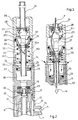
- the double-wire twisting spindle consists of the whorl 1, the turntable 2 with thread storage disk 3 and the stationary bobbin with a supply or delivery spool 5.
- the bobbin 4 consists of the bobbin case 6, the bobbin case 7 and that shown in FIGS. 2 and 4 Coil pot hollow hub 8.
- the coil pot is provided with magnets, not shown, which cooperate with magnets arranged outside the spindle in order to lock the coil pot 4.
- the bobbin 4 is mounted on the spindle rotor 12 by means of bearings 9 (FIG. 2) or 10, 11 (FIG. 4).
- the coil pot base 7 is provided with a radially running compressed air channel 13, to which a compressed air connection 14 (FIG. 1) can be made laterally, which is connected via a switch box 15 to a schematically illustrated compressed air source 16.
- a compressed air connection 14 FIG. 1
- annular compressed air duct 17 which runs through the hollow bobbin hub 8 and leads to an injector nozzle 19 which is arranged directly above the spindle rotor 12 and is directed towards the thread storage disk 3.
- the injector nozzle 19 consists of a tube piece 22 which is inserted centrally into the hollow bobbin hub 8 and which is connected on the one hand to the compressed air duct 17 and on the other hand is directed downwards to the spindle rotor 12.
- a plug-on sleeve 23 is plugged onto the hollow bobbin hub 8 forming a cylinder chamber 8.1 at its upper end, the upper end of which is closed by a central cylinder end wall 24.
- the push-on sleeve 23 is provided at its upper end with lateral air openings 25 which open into the cylinder chamber 8.1.
- a cylinder housing 26 is placed on the cylinder end wall 24 provided with a cylinder beech 24.1, which limits a further cylinder chamber 26.1 forming the brake housing.
- An essentially capsule-shaped brake cartridge 27 is accommodated in this cylinder housing 26 and bears against an upper, stationary brake surface ring 28 and against a lower, axially displaceable brake surface ring 29.
- the upper braking surface ring 28 is inserted into a cylinder sleeve 21.1 attached to the lower end of the thread inlet tube 21.
- the lower brake surface ring 29 is in a piston 30 having a stepped bore used, which is sealingly guided in the cylinder chamber 26.1 by means of a sealing ring 31.
- the piston 30 In the effective operating position of the thread brake shown in FIG. 2, the piston 30 is held in its upper position by a restoring force generated, for example, by a helical spring 32; this spring is supported between the underside of the piston 30 and the top of the cylinder end wall 24.
- the tube 33 is sealingly guided through the cylinder end wall 24 by means of a seal 34 inserted into the central opening of the cylinder end wall 24 and carries in the region of its lower end a second piston 35 which is sealingly guided in the lower cylinder chamber 8.1 by means of the seal 36.
- a holding or catching direction is preferably used in the form of at least three radially inwardly directed support cams 37, which serve to support a radially outwardly projecting collar 27.1 of the brake cartridge 27 over a partial area of the brake cartridge circumference when the lower brake surface ring 29 is shifted downward and the brake cartridge 27 falls down under the influence of gravity.
- a holding or catching direction is preferably used in the form of at least three radially inwardly directed support cams 37, which serve to support a radially outwardly projecting collar 27.1 of the brake cartridge 27 over a partial area of the brake cartridge circumference when the lower brake surface ring 29 is shifted downward and the brake cartridge 27 falls down under the influence of gravity.
- an injector nozzle 40 is inserted centrally into the thread storage disk 3.
- This injector nozzle 40 is supplied with compressed air from a compressed air source 41 shown schematically by a compressed air source 41 through the spindle whorl 1, in the manner described, for example, in DE-PS en 20 35 025 and 30 12 427.
- the injector nozzle is arranged so that when it is acted upon with compressed air, a compressed air jet enters the radially directed thread guide channel 3.1 of the thread storage disk 3, such that in the channel 12.1 axially guided through the spindle rotor 12 an upward pressure or suction air flow which is effective up to the thread brake is built up in order to the thread brake in the to open or ventilate shown in Figure 4.
- the piston system is designed as a triple piston.
- the tube 33 is extended beyond the second piston 35 by a further tube section 33.2, which is connected via at least one lateral opening 33.3 below the piston 35 to the cylinder chamber 42 receiving this piston.
- This pipe section 33.2 is sealingly guided in a cylinder end wall 43.
- the tube section 33.2 carries at its lower end a third piston 44 which can be sealingly displaced in a third cylinder chamber 45, into which at least one air opening 46 opens above the third piston 44.
- the bottom of the lower cylinder chamber 45 has a central opening in order to connect the tube 33 to the axial channel 12.1 of the spindle rotor 12.
Landscapes
- Engineering & Computer Science (AREA)
- Mechanical Engineering (AREA)
- Textile Engineering (AREA)
- Spinning Or Twisting Of Yarns (AREA)
Applications Claiming Priority (2)
| Application Number | Priority Date | Filing Date | Title |
|---|---|---|---|
| DE4103286A DE4103286C2 (de) | 1991-02-04 | 1991-02-04 | Doppeldraht-Zwirnspindel |
| DE4103286 | 1991-02-04 |
Publications (3)
| Publication Number | Publication Date |
|---|---|
| EP0498077A2 true EP0498077A2 (fr) | 1992-08-12 |
| EP0498077A3 EP0498077A3 (en) | 1992-09-09 |
| EP0498077B1 EP0498077B1 (fr) | 1996-03-06 |
Family
ID=6424334
Family Applications (1)
| Application Number | Title | Priority Date | Filing Date |
|---|---|---|---|
| EP91122255A Expired - Lifetime EP0498077B1 (fr) | 1991-02-04 | 1991-12-27 | Broche à retordre à double torsion |
Country Status (5)
| Country | Link |
|---|---|
| US (1) | US5155988A (fr) |
| EP (1) | EP0498077B1 (fr) |
| JP (1) | JP3108175B2 (fr) |
| CZ (1) | CZ281953B6 (fr) |
| DE (1) | DE4103286C2 (fr) |
Cited By (1)
| Publication number | Priority date | Publication date | Assignee | Title |
|---|---|---|---|---|
| DE4342244A1 (de) * | 1993-12-10 | 1995-06-14 | Lim Jin Tae | Nadeleinsetzvorrichtung für ein Garneinhaken in einer Zwei-Vier-Eins-Garnzwirnmaschine |
Families Citing this family (9)
| Publication number | Priority date | Publication date | Assignee | Title |
|---|---|---|---|---|
| DE4408262C2 (de) * | 1993-04-13 | 1996-03-14 | Palitex Project Co Gmbh | Einrichtung zum Einstellen von Kapselfadenbremsen an Zwirnmaschinen, insbesondere Doppeldraht-Zwirnmaschinen |
| DE19540790C1 (de) * | 1995-11-02 | 1996-12-05 | Palitex Project Co Gmbh | Zwirnspindel, insbesondere für eine mehrere Zwirnspindeln aufweisende Doppeldraht-Zwirnmaschine |
| DE19955399C2 (de) * | 1999-11-18 | 2001-10-04 | Volkmann Gmbh | Kablier- und Doppeldrahtzwirn-Spindel |
| DE10032141A1 (de) * | 2000-07-01 | 2002-01-17 | Volkmann Gmbh | Fadenbremse und mit einer solchen Fadenbremse ausgerüstete Spindeln, Doppeldraht-Zwirnspindeln und Doppeldraht-Zwirnmaschinen |
| DE10032140A1 (de) * | 2000-07-01 | 2002-01-17 | Volkmann Gmbh | Fadenbremse und mit einer solchen Fadenbremse ausgerüstete Spindeln, Doppeldraht-Zwirnspindeln und Doppeldraht-Zwirnmaschinen |
| DE102006029055A1 (de) * | 2006-06-24 | 2007-12-27 | Oerlikon Textile Gmbh & Co. Kg | Doppeldraht-Zwirnspindel mit druckluftbetätigter Einfädelvorrichtung |
| DE102009058979A1 (de) * | 2009-12-18 | 2011-06-22 | Oerlikon Textile GmbH & Co. KG, 42897 | Fadenbremse für eine Doppeldrahtzwirnspindel |
| CN103243421B (zh) * | 2013-04-19 | 2015-12-02 | 徐州斯尔克纤维科技股份有限公司 | 一种倍捻机的气动控制系统 |
| DE102015014299A1 (de) * | 2015-11-06 | 2017-05-11 | Saurer Germany Gmbh & Co. Kg | Außenfadenbremse, Kordier- oder Kabliermaschine mit einer Außenfadenbremse und Verfahren zum Betreiben einer solchen Kordier- oder Kabliermaschine |
Family Cites Families (6)
| Publication number | Priority date | Publication date | Assignee | Title |
|---|---|---|---|---|
| DE2830265C2 (de) * | 1978-07-10 | 1983-01-13 | Palitex Project-Company Gmbh, 4150 Krefeld | Doppeldraht-Zwirnspindel |
| DE2914656C2 (de) * | 1979-04-11 | 1982-04-22 | Palitex Project-Company Gmbh, 4150 Krefeld | Fadenbremse insbesondere für Doppeldraht-Zwirnspindeln |
| DE3012427A1 (de) * | 1980-03-31 | 1981-04-16 | Saurer-Allma Gmbh, 8960 Kempten | Doppeldrahtzwirnspindel mit druckluftbetaetigter einfaedelvorrichtung |
| DE3104748C2 (de) * | 1981-02-11 | 1984-11-08 | Palitex Project-Company Gmbh, 4150 Krefeld | Pneumatisch durchfädelbare Fadenbremse, insbesondere für eine Doppeldraht-Zwirnspindel |
| DE3243147C2 (de) * | 1982-11-22 | 1989-11-02 | Kraftwerk Union AG, 4330 Mülheim | Verfahren zur Meerwasseraufbereitung |
| DE3243157C2 (de) * | 1982-11-23 | 1985-01-24 | Palitex Project-Company Gmbh, 4150 Krefeld | Fadenbremse mit zugeordneter druckluftbetätigter Einfädelvorrichtung, insbesondere für Doppeldraht-Zwirnspindeln |
-
1991
- 1991-02-04 DE DE4103286A patent/DE4103286C2/de not_active Expired - Fee Related
- 1991-12-27 EP EP91122255A patent/EP0498077B1/fr not_active Expired - Lifetime
-
1992
- 1992-01-24 CZ CS92212A patent/CZ281953B6/cs unknown
- 1992-02-03 JP JP04017463A patent/JP3108175B2/ja not_active Expired - Fee Related
- 1992-02-04 US US07/830,598 patent/US5155988A/en not_active Expired - Fee Related
Cited By (1)
| Publication number | Priority date | Publication date | Assignee | Title |
|---|---|---|---|---|
| DE4342244A1 (de) * | 1993-12-10 | 1995-06-14 | Lim Jin Tae | Nadeleinsetzvorrichtung für ein Garneinhaken in einer Zwei-Vier-Eins-Garnzwirnmaschine |
Also Published As
| Publication number | Publication date |
|---|---|
| US5155988A (en) | 1992-10-20 |
| JP3108175B2 (ja) | 2000-11-13 |
| DE4103286A1 (de) | 1992-08-06 |
| DE4103286C2 (de) | 1993-10-28 |
| CZ281953B6 (cs) | 1997-04-16 |
| CS21292A3 (en) | 1992-08-12 |
| JPH04316619A (ja) | 1992-11-09 |
| EP0498077B1 (fr) | 1996-03-06 |
| EP0498077A3 (en) | 1992-09-09 |
Similar Documents
| Publication | Publication Date | Title |
|---|---|---|
| DE2830265C2 (de) | Doppeldraht-Zwirnspindel | |
| CH643211A5 (de) | Fadenbremse und mit einer derartigen fadenbremse ausgeruestete doppeldraht-zwirnspindel. | |
| DE2200686B2 (de) | Faserbandauflösevorrichtung | |
| EP1520824B1 (fr) | Dispositif pour la formation d'une réserve de fil et une bobine à fils croisés sur un tube-bobine | |
| EP0498077B1 (fr) | Broche à retordre à double torsion | |
| DE3104748C2 (de) | Pneumatisch durchfädelbare Fadenbremse, insbesondere für eine Doppeldraht-Zwirnspindel | |
| EP0620301B1 (fr) | Dispositif de réglage de freins de fil à capsule sur métiers à retordre, en particulier pour métiers à retordre à double torsion | |
| DE19955399A1 (de) | Kablier- und Doppeldrahtzwirn-Spindel | |
| CH658870A5 (de) | Doppeldraht-zwirnspindel. | |
| DE4010017C2 (de) | Spindel zum Herstellen eines Fadens | |
| DE3310438C2 (de) | Vorrichtung zur Veränderung des Durchmessers einer Ablaufhilfe für den Überkopfabzug eines auf eine Aufwickelspule aufzuwickelnden Fadens von einer Vorlagespule | |
| DE3243157A1 (de) | Fadenbremse mit zugeordneter druckluftbetaetigter einfaedelvorrichtung, insbesondere fuer doppeldraht-zwirnspindeln | |
| DE2843207C2 (de) | Doppeldrahtzwirnmaschine mit den einzelnen Spindeln zugeordneten pneumatischen Injektoren | |
| DE4404555C1 (de) | Verfahren zum getrennten Einfädeln von zwei von zwei gleichachsig übereinander angeordneten Vorlagespulen abgezogenen Einzelfäden in die zweigeteilte Hohlachse einer Doppeldraht-Zwirnspindel und Doppeldraht-Zwirnspindel | |
| DE1535570B1 (de) | Saugkanal zur Bildung einer Schleife eines Schussfadens an Webmaschinen mit Entnahme des Schussfadens von ortsfesten Spulen | |
| EP0464424B1 (fr) | Procédé pour réguler automatiquement la force de freinage d'un frein de fil situé dans la broche creuse d'une broche à retordre à double torsion et broche à retordre à double torsion équipée d'un tel frein de fil | |
| EP0721022B1 (fr) | Procédé d'enfilage dans l'alésage central de l'axe divisé en deux de deux bobines d'alimentation disposées l'une au dessus de l'autre dans le pot d'une broche à double torsion | |
| DE2461796C2 (de) | Doppeldrahtzwirnspindel mit einer im Bereich der Spindelhohlachse angeordneten druckluftgetätigten Einfädelvorrichtung | |
| DE2756504C3 (de) | Doppeldraht-Zwirnspindel mit aus einer Druckluftquelle betätigter Einfädelvorrichtung | |
| DE4010019A1 (de) | Spindel zum herstellen eines fadens | |
| DE1069044B (de) | Anzwirnvorrichtung für eine Streckzwirnmaschine | |
| DE1510853B1 (de) | Vorrichtung an einer Doppeldraht-Zwirnspindel zum Steuern von Fadenbremsen od.dgl. | |
| DE102015014299A1 (de) | Außenfadenbremse, Kordier- oder Kabliermaschine mit einer Außenfadenbremse und Verfahren zum Betreiben einer solchen Kordier- oder Kabliermaschine | |
| DE1535570C (de) | Saugkanal zur Bildung einer Schleife eines Schußfadens an Webmaschinen mit Entnahme des Schußfadens von ortsfesten Spulen | |
| DE8232731U1 (de) | Fadenbremse mit zugeordneter druckluftbetaetigter einfaedelvorrichtung, insbesondere fuer doppeldraht-zwirnspindeln |
Legal Events
| Date | Code | Title | Description |
|---|---|---|---|
| PUAI | Public reference made under article 153(3) epc to a published international application that has entered the european phase |
Free format text: ORIGINAL CODE: 0009012 |
|
| PUAL | Search report despatched |
Free format text: ORIGINAL CODE: 0009013 |
|
| AK | Designated contracting states |
Kind code of ref document: A2 Designated state(s): DE FR GB IT |
|
| AK | Designated contracting states |
Kind code of ref document: A3 Designated state(s): DE FR GB IT |
|
| 17P | Request for examination filed |
Effective date: 19921005 |
|
| 17Q | First examination report despatched |
Effective date: 19940328 |
|
| ITF | It: translation for a ep patent filed | ||
| GRAH | Despatch of communication of intention to grant a patent |
Free format text: ORIGINAL CODE: EPIDOS IGRA |
|
| GRAA | (expected) grant |
Free format text: ORIGINAL CODE: 0009210 |
|
| AK | Designated contracting states |
Kind code of ref document: B1 Designated state(s): FR IT |
|
| ET | Fr: translation filed | ||
| PLBE | No opposition filed within time limit |
Free format text: ORIGINAL CODE: 0009261 |
|
| STAA | Information on the status of an ep patent application or granted ep patent |
Free format text: STATUS: NO OPPOSITION FILED WITHIN TIME LIMIT |
|
| 26N | No opposition filed | ||
| PGFP | Annual fee paid to national office [announced via postgrant information from national office to epo] |
Ref country code: FR Payment date: 20011220 Year of fee payment: 11 |
|
| PG25 | Lapsed in a contracting state [announced via postgrant information from national office to epo] |
Ref country code: FR Free format text: LAPSE BECAUSE OF NON-PAYMENT OF DUE FEES Effective date: 20030901 |
|
| REG | Reference to a national code |
Ref country code: FR Ref legal event code: ST |
|
| PG25 | Lapsed in a contracting state [announced via postgrant information from national office to epo] |
Ref country code: IT Free format text: LAPSE BECAUSE OF NON-PAYMENT OF DUE FEES;WARNING: LAPSES OF ITALIAN PATENTS WITH EFFECTIVE DATE BEFORE 2007 MAY HAVE OCCURRED AT ANY TIME BEFORE 2007. THE CORRECT EFFECTIVE DATE MAY BE DIFFERENT FROM THE ONE RECORDED. Effective date: 20051227 |