EP0498128A1 - Procédé pour détermination des afflux ou des pertes des fluides au forage avec plate-forme de forage flottante - Google Patents
Procédé pour détermination des afflux ou des pertes des fluides au forage avec plate-forme de forage flottante Download PDFInfo
- Publication number
- EP0498128A1 EP0498128A1 EP91400302A EP91400302A EP0498128A1 EP 0498128 A1 EP0498128 A1 EP 0498128A1 EP 91400302 A EP91400302 A EP 91400302A EP 91400302 A EP91400302 A EP 91400302A EP 0498128 A1 EP0498128 A1 EP 0498128A1
- Authority
- EP
- European Patent Office
- Prior art keywords
- flow
- well
- fluid
- heave
- motion
- Prior art date
- Legal status (The legal status is an assumption and is not a legal conclusion. Google has not performed a legal analysis and makes no representation as to the accuracy of the status listed.)
- Granted
Links
Images


Classifications
-
- E—FIXED CONSTRUCTIONS
- E21—EARTH OR ROCK DRILLING; MINING
- E21B—EARTH OR ROCK DRILLING; OBTAINING OIL, GAS, WATER, SOLUBLE OR MELTABLE MATERIALS OR A SLURRY OF MINERALS FROM WELLS
- E21B21/00—Methods or apparatus for flushing boreholes, e.g. by use of exhaust air from motor
- E21B21/08—Controlling or monitoring pressure or flow of drilling fluid, e.g. automatic filling of boreholes, automatic control of bottom pressure
-
- E—FIXED CONSTRUCTIONS
- E21—EARTH OR ROCK DRILLING; MINING
- E21B—EARTH OR ROCK DRILLING; OBTAINING OIL, GAS, WATER, SOLUBLE OR MELTABLE MATERIALS OR A SLURRY OF MINERALS FROM WELLS
- E21B21/00—Methods or apparatus for flushing boreholes, e.g. by use of exhaust air from motor
- E21B21/001—Methods or apparatus for flushing boreholes, e.g. by use of exhaust air from motor specially adapted for underwater drilling
Definitions
- the present invention relates to a method for determining fluid influx or loss when drilling wells from a floating rig, for example a drill ship or a semi-submersible rig.
- bottom supported drilling rigs such as jack-up rigs can be used.
- Floating platforms such as drill ships or semi-submersible rigs can operate in much deeper water than bottom supported rigs but do suffer from problems in maintaining a steady positional relationship with the sea bed. While horizontal movements can be controlled to some degree by dynamic positioning systems and anchoring, vertical movement or "heave" due to wave action remains.
- a drilling fluid or mud in petroleum or geothermal well drilling.
- the mud is pumped into the drillstring at the surface and passes downwardly to the bit from where it is released into the borehole and returns to the surface in the annular space between the drillstring and borehole, carrying up cuttings from the bit back to the surface.
- the mud also serves other purposes such as the containment of formation fluids and support of the borehole itself.
- Fluid influx or a "kick"
- fluid loss loss circulation
- heave motion effectively changes the volume of the flow path for mud flow to and from the well making the detection of kicks or lost circulation difficult in the short term.
- a method of determining fluid influx or loss from a well being drilled from a floating vessel using a drilling fluid comprising monitoring the flow of fluid from the well to obtain a varying signal indicative of the variation in flow from the well, monitoring the heave motion of the vessel to obtain a varying signal indicative of said motion, using the signal indicative of the heave motion to calculate the expected variation in fluid flow from the well due to said motion, using said calculated flow to correct the varying flow signal to compensate for any flow component due to heave motion and monitoring the compensated signal for an indication of fluid influx or loss from the well.
- the observed flow can easily be corrected to remove any effects of heave motion so allowing faster correction and hence greater accuracy in anomalous flow detection.
- Other rig motion components such as roll which also affect the drilling fluid flow could also be compensated for in a similar manner.
- the compensated signal is compared with the measured flow into the well. The difference between these signals can be used to raise alarms where necessary.
- the flow measurement is typically obtained from a flow meter in the fluid output from the well and the heave motion is typically obtained from an encoder on a slip joint in the marine riser.
- Flow into the well can be calculated from the volume of mud pumped by the mud pumping system into the well.
- the compensated value is preferably compared with an upper and/or a lower threshold to determine fluid influx or loss respectively.
- the calculations should be performed simultaneously with continuous measurements and can be on a time averaged basis if required.
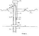
- the rig shown therein has parts omitted for reasons of clarity and comprises a vessel hull 10 which is floating in the water 12.
- the vessel can be a drilling ship or semi-submersible rig or other floating vessel and can be maintained in position by appropriate means such as anchoring or dynamic positioning means (not shown).
- a drillstring 14 passes from the rig to the sea bed 15, through a BOP stack 16 into the borehole 18.
- the vessel 10 and BOP stack 16 are connected by means of a marine riser 20 comprising a lower section 20, fixed to the BOP stack 16, and an upper section 20b fixed to the hull 10.
- the upper and lower sections 20a, 20b are connected by means of a telescopic joint or "slip joint" 22 to allow heave movement of the hull 10 without affecting the marine riser 20.
- drilling mud is pumped down the inside of the drillstring 14 to the bit (not shown) where it passes upwards to the surface through the annular space 24 between the drillstring 14 and the borehole 18.
- the mud passes from the borehole 18 to the vessel 10 through the marine riser 20 and returns to the circulating system (not shown) from an outflow 26.
- the amount of mud pumped into the well can be determined from the constant displacement pumps used to circulate the mud.
- a flow meter 28 is provided on the outflow 26 to monitor the amount of mud flowing from the well and an encoder 30 is provided in the slip joint 22 to monitor the relative vertical position of the hull 10 from the sea bed 15. The output from the flow meter 28, encoder 30 and other monitoring devices is fed to a processor 32 for analysis.
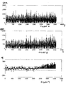
- the effect of heave is to cause Q o to vary between 0 and 1500 gallons/minute such that any influx or loss causing a change in Q o of 50-100 gallons/minute, which is a typical change which one would want to detect in the initial stages of such situations, would not be discernible.
- One embodiment of the present invention utilises adaptive filtering techniques to obtain a filter which models the relationship between the time differentiated heave channel signal as the filter input and the flow-out signal as the filter output.
- Suitable algorithms are available in the literature, for example the "least mean squares (LMS)" method gives adequate performance in this application.
- LMS least mean squares
- the adaptive filter recursively provides estimates of the impulse response vector "h(t)” which forms the modelled relation of the slip joint signal to the dynamic component of the flow signal.
- the adaptive nature of the filter ensures that the model changes slowly with time in response to changing wave conditions and mud flow velocities.
- an estimate of the expected dynamic flow component can be obtained by convolving h(t) with the current segment of heave data to obtain the current predicted flow as the output from the filter. This predicted flow variation due to heave motion can then be subtracted from the measured flow, either or an instantaneous or time averaged basis, to produce the corrected flow measurements.
- Adaptive filtering techniques as described above have the function of adjusting the amplitudes and/or phases of the input data to match those of a "training signal" which in this case is provided by sections of flow data having dynamic components dominated by the rig motion. From Figures 2 and 3 it is evident that one narrow-band signal dominates both the heave and the flow data. A good estimate of the required model with which to obtain the dynamic flow estimate can therefore be obtained by estimating the required amplitude and phase processing of this frequency component in the heave measurement. This has the advantage that the necessary processing can be economically applied in the time-domain. A detailed implementation of this processing technique, is described as follows:
Landscapes
- Engineering & Computer Science (AREA)
- Geology (AREA)
- Life Sciences & Earth Sciences (AREA)
- Mining & Mineral Resources (AREA)
- Physics & Mathematics (AREA)
- Environmental & Geological Engineering (AREA)
- Fluid Mechanics (AREA)
- Mechanical Engineering (AREA)
- General Life Sciences & Earth Sciences (AREA)
- Geochemistry & Mineralogy (AREA)
- Measuring Volume Flow (AREA)
- Indicating Or Recording The Presence, Absence, Or Direction Of Movement (AREA)
- Earth Drilling (AREA)
- Cyclones (AREA)
Priority Applications (5)
| Application Number | Priority Date | Filing Date | Title |
|---|---|---|---|
| DE69107606T DE69107606D1 (de) | 1991-02-07 | 1991-02-07 | Verfahren zur Bestimmung von Zuströmungen oder Spulungsverlusten beim Bohren mittels schwimmender Bohrinseln. |
| EP91400302A EP0498128B1 (fr) | 1991-02-07 | 1991-02-07 | Procédé pour détermination des afflux ou des pertes des fluides au forage avec plate-forme de forage flottante |
| US07/832,161 US5205165A (en) | 1991-02-07 | 1992-02-06 | Method for determining fluid influx or loss in drilling from floating rigs |
| CA002060736A CA2060736C (fr) | 1991-02-07 | 1992-02-06 | Methode servant a determiner l'afflux ou la perte de liquide dans les operations sur plate-forme de forage sous-marin |
| NO920486A NO306912B1 (no) | 1991-02-07 | 1992-02-06 | Fremgangsmåte for bestemmelse av fluidinnströmning eller -tap ved boring fra flytende rigger |
Applications Claiming Priority (1)
| Application Number | Priority Date | Filing Date | Title |
|---|---|---|---|
| EP91400302A EP0498128B1 (fr) | 1991-02-07 | 1991-02-07 | Procédé pour détermination des afflux ou des pertes des fluides au forage avec plate-forme de forage flottante |
Publications (2)
| Publication Number | Publication Date |
|---|---|
| EP0498128A1 true EP0498128A1 (fr) | 1992-08-12 |
| EP0498128B1 EP0498128B1 (fr) | 1995-02-22 |
Family
ID=8208541
Family Applications (1)
| Application Number | Title | Priority Date | Filing Date |
|---|---|---|---|
| EP91400302A Expired - Lifetime EP0498128B1 (fr) | 1991-02-07 | 1991-02-07 | Procédé pour détermination des afflux ou des pertes des fluides au forage avec plate-forme de forage flottante |
Country Status (5)
| Country | Link |
|---|---|
| US (1) | US5205165A (fr) |
| EP (1) | EP0498128B1 (fr) |
| CA (1) | CA2060736C (fr) |
| DE (1) | DE69107606D1 (fr) |
| NO (1) | NO306912B1 (fr) |
Cited By (5)
| Publication number | Priority date | Publication date | Assignee | Title |
|---|---|---|---|---|
| GB2273512A (en) * | 1992-12-12 | 1994-06-22 | Timothy Peter Blatch | Compensation for mud flow indicators |
| EP2806100A1 (fr) * | 2013-05-24 | 2014-11-26 | Geoservices Equipements | Procédé pour contrôler le forage d'un puits au moyen d'une installation de forage flottante et système de surveillance associé |
| EP2949858A1 (fr) * | 2014-05-13 | 2015-12-02 | Weatherford Technology Holdings, LLC | Système de déflecteur marin à détection en temps réel d'un coup de pression ou de perte |
| GB2564507A (en) * | 2017-07-11 | 2019-01-16 | Equinor Energy As | Influx and loss detection |
| WO2024057230A1 (fr) * | 2022-09-14 | 2024-03-21 | Exebenus AS | Analyse d'appareil de forage basée sur la fréquence |
Families Citing this family (22)
| Publication number | Priority date | Publication date | Assignee | Title |
|---|---|---|---|---|
| JP4488547B2 (ja) * | 1999-04-06 | 2010-06-23 | 三井造船株式会社 | 浮体式リグの位置保持制御方法および制御装置 |
| US6499540B2 (en) * | 2000-12-06 | 2002-12-31 | Conoco, Inc. | Method for detecting a leak in a drill string valve |
| US20020112888A1 (en) | 2000-12-18 | 2002-08-22 | Christian Leuchtenberg | Drilling system and method |
| US8844652B2 (en) | 2007-10-23 | 2014-09-30 | Weatherford/Lamb, Inc. | Interlocking low profile rotating control device |
| US8286734B2 (en) | 2007-10-23 | 2012-10-16 | Weatherford/Lamb, Inc. | Low profile rotating control device |
| GB2457278B (en) * | 2008-02-08 | 2010-07-21 | Schlumberger Holdings | Detection of deposits in flow lines or pipe lines |
| US9359853B2 (en) | 2009-01-15 | 2016-06-07 | Weatherford Technology Holdings, Llc | Acoustically controlled subsea latching and sealing system and method for an oilfield device |
| US8322432B2 (en) | 2009-01-15 | 2012-12-04 | Weatherford/Lamb, Inc. | Subsea internal riser rotating control device system and method |
| US9528334B2 (en) | 2009-07-30 | 2016-12-27 | Halliburton Energy Services, Inc. | Well drilling methods with automated response to event detection |
| US9567843B2 (en) * | 2009-07-30 | 2017-02-14 | Halliburton Energy Services, Inc. | Well drilling methods with event detection |
| US8347983B2 (en) | 2009-07-31 | 2013-01-08 | Weatherford/Lamb, Inc. | Drilling with a high pressure rotating control device |
| GB2478119A (en) * | 2010-02-24 | 2011-08-31 | Managed Pressure Operations Llc | A drilling system having a riser closure mounted above a telescopic joint |
| US8347982B2 (en) | 2010-04-16 | 2013-01-08 | Weatherford/Lamb, Inc. | System and method for managing heave pressure from a floating rig |
| US9175542B2 (en) | 2010-06-28 | 2015-11-03 | Weatherford/Lamb, Inc. | Lubricating seal for use with a tubular |
| GB2490156A (en) | 2011-04-21 | 2012-10-24 | Managed Pressure Operations | Slip joint for a riser in an offshore drilling system |
| EP2729661A4 (fr) * | 2011-07-05 | 2015-12-02 | Halliburton Energy Services Inc | Procédés de forage de puits comprenant réponse automatique à une détection d'événement |
| US9033048B2 (en) * | 2011-12-28 | 2015-05-19 | Hydril Usa Manufacturing Llc | Apparatuses and methods for determining wellbore influx condition using qualitative indications |
| WO2014055090A1 (fr) * | 2012-10-05 | 2014-04-10 | Halliburton Energy Services, Inc. | Détection de venues et de pertes lors de forage à partir d'un bâtiment flottant |
| WO2014189992A2 (fr) * | 2013-05-23 | 2014-11-27 | Shell Oil Company | Détection d'afflux lors d'événements d'arrêt de pompes durant un forage de puits |
| GB2521373A (en) | 2013-12-17 | 2015-06-24 | Managed Pressure Operations | Apparatus and method for degassing drilling fluid |
| GB2521374A (en) | 2013-12-17 | 2015-06-24 | Managed Pressure Operations | Drilling system and method of operating a drilling system |
| CN109339768B (zh) * | 2018-10-23 | 2022-04-22 | 西南石油大学 | 一种钻井微溢流随钻监测方法 |
Citations (5)
| Publication number | Priority date | Publication date | Assignee | Title |
|---|---|---|---|---|
| US3760891A (en) * | 1972-05-19 | 1973-09-25 | Offshore Co | Blowout and lost circulation detector |
| US4282939A (en) * | 1979-06-20 | 1981-08-11 | Exxon Production Research Company | Method and apparatus for compensating well control instrumentation for the effects of vessel heave |
| GB2106961A (en) * | 1981-09-28 | 1983-04-20 | Exxon Production Research Co | Controlling the flow of drilling fluid in a wellbore |
| US4535851A (en) * | 1983-03-09 | 1985-08-20 | Kirkpatrick-Mcgee, Inc. | Fluid flow measurement system |
| US4610161A (en) * | 1985-07-05 | 1986-09-09 | Exxon Production Research Co. | Method and apparatus for determining fluid circulation conditions in well drilling operations |
Family Cites Families (19)
| Publication number | Priority date | Publication date | Assignee | Title |
|---|---|---|---|---|
| US3614761A (en) * | 1969-11-03 | 1971-10-19 | Dresser Ind | Method and apparatus for monitoring potential or lost circulation in an earth borehole |
| US3729986A (en) * | 1970-08-28 | 1973-05-01 | L Leonard | Measuring and servicing the drilling fluid in a well |
| US3646808A (en) * | 1970-08-28 | 1972-03-07 | Loren W Leonard | Method for automatically monitoring and servicing the drilling fluid condition in a well bore |
| US3813935A (en) * | 1971-01-12 | 1974-06-04 | D Tanguy | Methods and apparatus for detecting the entry of formation gas into a well bore |
| US3802502A (en) * | 1972-04-10 | 1974-04-09 | Weston Instruments Inc | Apparatus for detecting the entry of formation gas into a well bore |
| US3821726A (en) * | 1972-05-08 | 1974-06-28 | Santa Fe Int Corp | Blow out sensor |
| US3841152A (en) * | 1973-02-02 | 1974-10-15 | Halliburton Co | Drilling conditions monitor |
| US3910110A (en) * | 1973-10-04 | 1975-10-07 | Offshore Co | Motion compensated blowout and loss circulation detection |
| US3976148A (en) * | 1975-09-12 | 1976-08-24 | The Offshore Company | Method and apparatus for determining onboard a heaving vessel the flow rate of drilling fluid flowing out of a wellhole and into a telescoping marine riser connecting between the wellhouse and the vessel |
| US4299123A (en) * | 1979-10-15 | 1981-11-10 | Dowdy Felix A | Sonic gas detector for rotary drilling system |
| US4492865A (en) * | 1982-02-04 | 1985-01-08 | Nl Industries, Inc. | Borehole influx detector and method |
| US4527425A (en) * | 1982-12-10 | 1985-07-09 | Nl Industries, Inc. | System for detecting blow out and lost circulation in a borehole |
| US4733233A (en) * | 1983-06-23 | 1988-03-22 | Teleco Oilfield Services Inc. | Method and apparatus for borehole fluid influx detection |
| US4733232A (en) * | 1983-06-23 | 1988-03-22 | Teleco Oilfield Services Inc. | Method and apparatus for borehole fluid influx detection |
| US4565086A (en) * | 1984-01-20 | 1986-01-21 | Baker Drilling Equipment Company | Method and apparatus for detecting entrained gases in fluids |
| US4553429A (en) * | 1984-02-09 | 1985-11-19 | Exxon Production Research Co. | Method and apparatus for monitoring fluid flow between a borehole and the surrounding formations in the course of drilling operations |
| US4606415A (en) * | 1984-11-19 | 1986-08-19 | Texaco Inc. | Method and system for detecting and identifying abnormal drilling conditions |
| FR2618181B1 (fr) * | 1987-07-15 | 1989-12-15 | Forex Neptune Sa | Procede de detection d'une venue de fluide pouvant presager une eruption dans un puits en cours de forage. |
| US4980642A (en) * | 1990-04-20 | 1990-12-25 | Baroid Technology, Inc. | Detection of influx of fluids invading a borehole |
-
1991
- 1991-02-07 DE DE69107606T patent/DE69107606D1/de not_active Expired - Lifetime
- 1991-02-07 EP EP91400302A patent/EP0498128B1/fr not_active Expired - Lifetime
-
1992
- 1992-02-06 NO NO920486A patent/NO306912B1/no not_active IP Right Cessation
- 1992-02-06 US US07/832,161 patent/US5205165A/en not_active Expired - Lifetime
- 1992-02-06 CA CA002060736A patent/CA2060736C/fr not_active Expired - Fee Related
Patent Citations (5)
| Publication number | Priority date | Publication date | Assignee | Title |
|---|---|---|---|---|
| US3760891A (en) * | 1972-05-19 | 1973-09-25 | Offshore Co | Blowout and lost circulation detector |
| US4282939A (en) * | 1979-06-20 | 1981-08-11 | Exxon Production Research Company | Method and apparatus for compensating well control instrumentation for the effects of vessel heave |
| GB2106961A (en) * | 1981-09-28 | 1983-04-20 | Exxon Production Research Co | Controlling the flow of drilling fluid in a wellbore |
| US4535851A (en) * | 1983-03-09 | 1985-08-20 | Kirkpatrick-Mcgee, Inc. | Fluid flow measurement system |
| US4610161A (en) * | 1985-07-05 | 1986-09-09 | Exxon Production Research Co. | Method and apparatus for determining fluid circulation conditions in well drilling operations |
Cited By (9)
| Publication number | Priority date | Publication date | Assignee | Title |
|---|---|---|---|---|
| GB2273512A (en) * | 1992-12-12 | 1994-06-22 | Timothy Peter Blatch | Compensation for mud flow indicators |
| EP2806100A1 (fr) * | 2013-05-24 | 2014-11-26 | Geoservices Equipements | Procédé pour contrôler le forage d'un puits au moyen d'une installation de forage flottante et système de surveillance associé |
| EP2949858A1 (fr) * | 2014-05-13 | 2015-12-02 | Weatherford Technology Holdings, LLC | Système de déflecteur marin à détection en temps réel d'un coup de pression ou de perte |
| US9822630B2 (en) | 2014-05-13 | 2017-11-21 | Weatherford Technology Holdings, Llc | Marine diverter system with real time kick or loss detection |
| GB2564507A (en) * | 2017-07-11 | 2019-01-16 | Equinor Energy As | Influx and loss detection |
| GB2564507B (en) * | 2017-07-11 | 2020-11-04 | Equinor Energy As | Influx and loss detection |
| US11384612B2 (en) | 2017-07-11 | 2022-07-12 | Equinor Energy As | Method and system for monitoring influx and loss events in a wellbore |
| US12509951B2 (en) | 2017-07-11 | 2025-12-30 | Equinor Energy As | Method and system for monitoring influx and loss events in a wellbore |
| WO2024057230A1 (fr) * | 2022-09-14 | 2024-03-21 | Exebenus AS | Analyse d'appareil de forage basée sur la fréquence |
Also Published As
| Publication number | Publication date |
|---|---|
| NO306912B1 (no) | 2000-01-10 |
| CA2060736C (fr) | 2002-08-06 |
| EP0498128B1 (fr) | 1995-02-22 |
| NO920486L (no) | 1992-08-10 |
| NO920486D0 (no) | 1992-02-06 |
| US5205165A (en) | 1993-04-27 |
| DE69107606D1 (de) | 1995-03-30 |
| CA2060736A1 (fr) | 1992-08-08 |
Similar Documents
| Publication | Publication Date | Title |
|---|---|---|
| EP0498128B1 (fr) | Procédé pour détermination des afflux ou des pertes des fluides au forage avec plate-forme de forage flottante | |
| US4282939A (en) | Method and apparatus for compensating well control instrumentation for the effects of vessel heave | |
| CA1057081A (fr) | Appareil et methode permettant de mesurer abord d'un navire le debit du fluide de forage circulant dans une colonne montante, du puits de forage au navire | |
| CA2290043C (fr) | Systeme de surveillance du debit du fluide de forage | |
| US4610161A (en) | Method and apparatus for determining fluid circulation conditions in well drilling operations | |
| EP0621397B1 (fr) | Procédé et appareil pour détecter une venue de fluide dans un puits pendant le forage | |
| US5006845A (en) | Gas kick detector | |
| US4208906A (en) | Mud gas ratio and mud flow velocity sensor | |
| US9429007B2 (en) | Managed pressure drilling with rig heave compensation | |
| AU2002219322B2 (en) | Closed loop fluid-handing system for well drilling | |
| EP0302558B1 (fr) | Procédé d'analyse des venues de fluides dans les puits d'hydrocarbures | |
| US5154078A (en) | Kick detection during drilling | |
| US3910110A (en) | Motion compensated blowout and loss circulation detection | |
| Speers et al. | Delta flow: An accurate, reliable system for detecting kicks and loss of circulation during drilling | |
| US7313052B2 (en) | System and methods of communicating over noisy communication channels | |
| CN103184841A (zh) | 用于使用定性指示确定井孔涌入状态的设备和方法 | |
| US4840061A (en) | Method of detecting a fluid influx which could lead to a blow-out during the drilling of a borehole | |
| NO20220430A1 (en) | Prospective kick loss detection for off-shore drilling | |
| US4099582A (en) | Drilling fluid compensation device | |
| GB2275778A (en) | Method and system for hookload measurements | |
| Doria et al. | Kick detection in floating drilling rigs | |
| US20210079742A1 (en) | Method for quantifying the volumetric flow rate of a flow of a drilling mud in a floating structure for subsoil drilling | |
| Agbakwuru et al. | Characterization of Dynamic Pressure Response in Vertical Two Phase Flow | |
| CA1135251A (fr) | Methode et dispositif de compensation sur l'instrumentation d'un navire de forage en haute mer agite par la houle | |
| Ojinnaka et al. | Early Kick Detection using Real-Time Data Analysis with a Lumped Parameter Model |
Legal Events
| Date | Code | Title | Description |
|---|---|---|---|
| PUAI | Public reference made under article 153(3) epc to a published international application that has entered the european phase |
Free format text: ORIGINAL CODE: 0009012 |
|
| AK | Designated contracting states |
Kind code of ref document: A1 Designated state(s): DE DK FR GB IT NL |
|
| RAP1 | Party data changed (applicant data changed or rights of an application transferred) |
Owner name: SEDCO FOREX TECHNOLOGY INC. |
|
| 17P | Request for examination filed |
Effective date: 19930125 |
|
| 17Q | First examination report despatched |
Effective date: 19931108 |
|
| 111L | Licence recorded |
Free format text: 0100 VARCO INTERNATIONAL, INC. |
|
| RAP1 | Party data changed (applicant data changed or rights of an application transferred) |
Owner name: SERVICES PETROLIERS SCHLUMBERGER, (FORMERLY SOCIE Owner name: SEDCO FOREX TECHNOLOGY INC. |
|
| GRAA | (expected) grant |
Free format text: ORIGINAL CODE: 0009210 |
|
| AK | Designated contracting states |
Kind code of ref document: B1 Designated state(s): DE DK FR GB IT NL |
|
| PG25 | Lapsed in a contracting state [announced via postgrant information from national office to epo] |
Ref country code: IT Free format text: LAPSE BECAUSE OF FAILURE TO SUBMIT A TRANSLATION OF THE DESCRIPTION OR TO PAY THE FEE WITHIN THE PRE;WARNING: LAPSES OF ITALIAN PATENTS WITH EFFECTIVE DATE BEFORE 2007 MAY HAVE OCCURRED AT ANY TIME BEFORE 2007. THE CORRECT EFFECTIVE DATE MAY BE DIFFERENT FROM THE ONE RECORDED.SCRIBED TIME-LIMIT Effective date: 19950222 Ref country code: NL Free format text: LAPSE BECAUSE OF FAILURE TO SUBMIT A TRANSLATION OF THE DESCRIPTION OR TO PAY THE FEE WITHIN THE PRESCRIBED TIME-LIMIT Effective date: 19950222 Ref country code: DK Effective date: 19950222 |
|
| REF | Corresponds to: |
Ref document number: 69107606 Country of ref document: DE Date of ref document: 19950330 |
|
| PG25 | Lapsed in a contracting state [announced via postgrant information from national office to epo] |
Ref country code: DE Effective date: 19950523 |
|
| ET | Fr: translation filed | ||
| NLV1 | Nl: lapsed or annulled due to failure to fulfill the requirements of art. 29p and 29m of the patents act | ||
| PLBE | No opposition filed within time limit |
Free format text: ORIGINAL CODE: 0009261 |
|
| STAA | Information on the status of an ep patent application or granted ep patent |
Free format text: STATUS: NO OPPOSITION FILED WITHIN TIME LIMIT |
|
| 26N | No opposition filed | ||
| K2C3 | Correction of patent specification (complete document) published |
Effective date: 19950222 |
|
| REG | Reference to a national code |
Ref country code: GB Ref legal event code: IF02 |
|
| PGFP | Annual fee paid to national office [announced via postgrant information from national office to epo] |
Ref country code: GB Payment date: 20090227 Year of fee payment: 19 |
|
| PGFP | Annual fee paid to national office [announced via postgrant information from national office to epo] |
Ref country code: FR Payment date: 20090217 Year of fee payment: 19 |
|
| GBPC | Gb: european patent ceased through non-payment of renewal fee |
Effective date: 20100207 |
|
| REG | Reference to a national code |
Ref country code: FR Ref legal event code: ST Effective date: 20101029 |
|
| PG25 | Lapsed in a contracting state [announced via postgrant information from national office to epo] |
Ref country code: FR Free format text: LAPSE BECAUSE OF NON-PAYMENT OF DUE FEES Effective date: 20100301 |
|
| PG25 | Lapsed in a contracting state [announced via postgrant information from national office to epo] |
Ref country code: GB Free format text: LAPSE BECAUSE OF NON-PAYMENT OF DUE FEES Effective date: 20100207 |