EP0498146A2 - Passage rotatif pour deux fluides différents - Google Patents
Passage rotatif pour deux fluides différents Download PDFInfo
- Publication number
- EP0498146A2 EP0498146A2 EP92100036A EP92100036A EP0498146A2 EP 0498146 A2 EP0498146 A2 EP 0498146A2 EP 92100036 A EP92100036 A EP 92100036A EP 92100036 A EP92100036 A EP 92100036A EP 0498146 A2 EP0498146 A2 EP 0498146A2
- Authority
- EP
- European Patent Office
- Prior art keywords
- hollow shaft
- housing
- inner sleeve
- mechanical seal
- rings
- Prior art date
- Legal status (The legal status is an assumption and is not a legal conclusion. Google has not performed a legal analysis and makes no representation as to the accuracy of the status listed.)
- Withdrawn
Links
Images
Classifications
-
- F—MECHANICAL ENGINEERING; LIGHTING; HEATING; WEAPONS; BLASTING
- F16—ENGINEERING ELEMENTS AND UNITS; GENERAL MEASURES FOR PRODUCING AND MAINTAINING EFFECTIVE FUNCTIONING OF MACHINES OR INSTALLATIONS; THERMAL INSULATION IN GENERAL
- F16L—PIPES; JOINTS OR FITTINGS FOR PIPES; SUPPORTS FOR PIPES, CABLES OR PROTECTIVE TUBING; MEANS FOR THERMAL INSULATION IN GENERAL
- F16L27/00—Adjustable joints; Joints allowing movement
- F16L27/08—Adjustable joints; Joints allowing movement allowing adjustment or movement only about the axis of one pipe
- F16L27/087—Joints with radial fluid passages
-
- B—PERFORMING OPERATIONS; TRANSPORTING
- B23—MACHINE TOOLS; METAL-WORKING NOT OTHERWISE PROVIDED FOR
- B23Q—DETAILS, COMPONENTS, OR ACCESSORIES FOR MACHINE TOOLS, e.g. ARRANGEMENTS FOR COPYING OR CONTROLLING; MACHINE TOOLS IN GENERAL CHARACTERISED BY THE CONSTRUCTION OF PARTICULAR DETAILS OR COMPONENTS; COMBINATIONS OR ASSOCIATIONS OF METAL-WORKING MACHINES, NOT DIRECTED TO A PARTICULAR RESULT
- B23Q11/00—Accessories fitted to machine tools for keeping tools or parts of the machine in good working condition or for cooling work; Safety devices specially combined with or arranged in, or specially adapted for use in connection with, machine tools
- B23Q11/10—Arrangements for cooling or lubricating tools or work
- B23Q11/1015—Arrangements for cooling or lubricating tools or work by supplying a cutting liquid through the spindle
- B23Q11/103—Rotary joints specially adapted for feeding the cutting liquid to the spindle
-
- F—MECHANICAL ENGINEERING; LIGHTING; HEATING; WEAPONS; BLASTING
- F16—ENGINEERING ELEMENTS AND UNITS; GENERAL MEASURES FOR PRODUCING AND MAINTAINING EFFECTIVE FUNCTIONING OF MACHINES OR INSTALLATIONS; THERMAL INSULATION IN GENERAL
- F16L—PIPES; JOINTS OR FITTINGS FOR PIPES; SUPPORTS FOR PIPES, CABLES OR PROTECTIVE TUBING; MEANS FOR THERMAL INSULATION IN GENERAL
- F16L39/00—Joints or fittings for double-walled or multi-channel pipes or pipe assemblies
- F16L39/04—Joints or fittings for double-walled or multi-channel pipes or pipe assemblies allowing adjustment or movement
Definitions
- the invention relates to a rotary feedthrough for two different fluids, in particular for machine tools, with a fixed housing, with a central flow channel for the first fluid and at least one parallel second flow channel for the second fluid, with a hollow shaft rotatably and axially immovably mounted therein two separate inflow channels provided in the housing for the two fluids and with two mechanical seal arrangements arranged between them and the hollow shaft and arranged coaxially to the axis of rotation, via which the fluids can be fed separately to the flow channels, the first mechanical seal arrangement being located centrally between the (inner) lying in the housing End of the hollow shaft and a housing part (housing cover) having the first inflow channel is arranged, while the second mechanical seal arrangement concentrically surrounds the hollow shaft and rotates together with the hollow shaft s, with at least one radial passage provided with a sliding ring, and two sliding rings constantly resting on its two end faces under spring pressure and resting relative to the housing, and wherein the hollow shaft has at least one radial bore which connects one
- a clamping device (tool clamp) is often provided in the interior of the hollow machine tool spindle.
- This clamping device has a pull rod running coaxially to the spindle axis, the front end of which is provided in the area of the tool holder with a collet acting on the tool.
- the inner end of the pull rod is passed through a hydraulically operating, so-called release unit, which serves to actuate the tensioning device.
- hydraulic oil Via the first inflow channel, the first mechanical seal arrangement and the parallel second flow channel, hydraulic oil can be supplied to the release unit under high pressure while the machine tool spindle is at a standstill, whereby the release unit shifts the pull rod in the machine tool spindle and the collet releases the workpiece.
- the pull rod is hollow and its end protruding from the release unit is connected to the zantral flow channel of the hollow shaft.
- the rotating union allows the cooling lubricant to be supplied from the stationary housing to the rotating pull rod via the second inflow channel and the second mechanical seal arrangement.
- Rotary unions for two different fluids are known in a wide variety of designs and for a wide variety of purposes.
- a rotary union of the type described at the beginning is suitable for wet machining, in which cooling lubricant is constantly fed to the rotating tool, but there are considerable problems with dry machining. Since the mechanical seals of the second mechanical seal arrangement would be destroyed quickly at higher spindle speeds due to the lack of lubrication and the lack of cooling, the second mechanical seal arrangement must also be supplied with cooling lubricant during dry machining.
- a spring-loaded check valve is installed in the pull rod or the hollow shaft, which blocks the flow channel in the hollow shaft or the hollow pull rod during dry machining when the coolant is fed under low pressure to the rotating union .
- this check valve gives rise to further problems because it interferes with the flow of coolant during wet machining.
- the sliding rings of the second mechanical seal arrangement are only insufficiently cooled even when a check valve is used, because there is no forced circulation of the cooling lubricant. For this reason, the known rotary feedthrough is not suitable for higher spindle speeds, and there is increased wear of the same due to the insufficient cooling of the slide rings in dry machining.
- cooling lubricant must be added again to the second mechanical seal arrangement even after continuous dry machining after each tool change and blowout.
- Rotary unions are also known (DE 35 42 014 C1), in which a sliding ring of the mechanical seal arrangement can be lifted off the other sliding ring during dry machining.
- the sealing surfaces are extremely flat and very hard. It cannot be avoided that small amounts of solid particles are contained in the cooling lubricant. Get at lifted sliding rings solid particles between the sealing surfaces and then the sliding rings are pressed together again, then the solid particles lead to a rapid destruction of the mechanical seal.
- a coating can also form on the slide rings, which later leads to increased leakage when the slide rings are pressed together again.
- DE 31 20 115 C2 discloses a rotary feedthrough for transferring a fluid that is only intermittently present from a stationary to a rotating component.
- the sealing rings are only effective there if they are actually required and fluid transfer is to take place. This is achieved there in that a sealing application of the sealing rings, which are arranged on a rotating hollow shaft, can take place on associated mating surfaces of the stationary housing only when the fluid is being transferred.
- a cylindrical counter surface and a conical surface inclined towards the counter surface are assigned to the sealing rings in the housing and the hollow shaft is axially displaceable relative to the housing in such a way that the sealing rings move from a position without contact to the conical surface via the respective conical surface into the Area of the associated counter surface can be brought, wherein they are pressed radially against the counter surface.
- this configuration requires sealing rings made of rubber-elastic material. Since, when the fluid is supplied, the sealing rings rub against the cylindrical counter surfaces of the housing, there is considerable wear at high speeds and, in addition, such radially pressed sealing rings made of rubber-elastic material are only suitable for relatively low pressures, in contrast to axially pressed sliding rings.
- the invention is therefore based on the object of providing a rotary leadthrough for two different fluids, in particular for machine tool spindles, of the type mentioned at the outset, which enables dry machining even at high speeds without wear of the slide rings of the second mechanical seal arrangement and in which the flow through the central flow channel is unimpeded can be done.
- the second mechanical seal arrangement is axially displaceable relative to the housing and the hollow shaft
- the rotatable sliding ring is arranged in a rotationally fixed manner with an inner sleeve concentrically surrounding the hollow shaft, which can be coupled and axially displaceable
- the two are at rest Sliding rings are arranged in an axially displaceable outer sleeve concentrically surrounding the inner sleeve, which has an annular piston which can be displaced in a cylinder space of the housing
- the hollow shaft in the displacement area of the inner sleeve has three sections which are tapered in diameter towards the hollow shaft end and the inner wall of the inner sleeve Bush have three correspondingly tapered sections in diameter
- the inner sleeve at the beginning of the second and third section has O-rings, which only in the coupled state of the inner sleeve to the corresponding diameter
- a Sections of the hollow shaft rest and seal an annular space between them, which
- the invention is therefore based on the idea of arranging the second mechanical seal arrangement in jointly displaceable bushes in order to decouple the second mechanical seal arrangement from the hollow shaft by means of axial displacement during dry running, ie when no fluid is to be passed over the second mechanical seal arrangement. While the machine tool spindle rotates together with the hollow shaft during dry machining, the uncoupled second mechanical seal arrangement rests. As a result, no friction, no wear and no heating occurs on the sliding rings of the second mechanical seal arrangement, so that the second mechanical seal arrangement also does not need to be cooled when running dry. As a result, a check valve in the hollow shaft or the tie rod can also be omitted and an unimpeded flow of cooling lubricant is ensured during wet machining.
- the O-rings are not in contact with the hollow shaft when running dry, so that no wear or heating can occur on the O-rings. If cooling lubricant is to be added to the tool during wet machining, then the outer sleeve is moved hydraulically or pneumatically with respect to the hollow shaft by its ring piston. It takes the inner sleeve with it, which means that it is non-rotatably coupled to the hollow shaft and the inner sleeve is also sealed against the hollow shaft via the O-rings.
- the inner sleeve coupled to the hollow shaft rotates together with the hollow shaft so that there is no relative movement between the O-rings and the hollow shaft and wear on the O-rings is thus avoided even when wet machining.
- the second mechanical seal assembly is completely uncoupled from the hollow shaft during dry running, the new rotary union is also suitable for high speeds.
- the first Rotary feedthrough in fact poses no problems, since cooling and lubrication of the sliding rings is ensured here by the constant supply of a fluid, and since the central arrangement of the sliding rings has a relatively small diameter and the sliding speeds are accordingly relatively low.
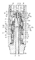
- the drawing shows an axial section of the rotary union, on the left in the coupled state of the second mechanical seal arrangement when two different fluids are passed through, on the right in the uncoupled state.
- the hollow shaft 2 is rotatably and axially immovable by means of the bearings 3, 4.
- the hollow shaft 2 has a central flow channel 5, into which one end of a tie rod (not shown) of a clamping device arranged in a machine tool spindle can engage.
- the hollow shaft 2 has a second flow channel 6 running parallel to the central flow channel 5.
- the outer end 2b of the hollow shaft 2 can be connected to the so-called release unit of the clamping device, this release unit being to be supplied with hydraulic oil under high pressure via the flow channel 6 while the machine tool spindle is at a standstill.
- the slide ring 7a of a first mechanical seal arrangement 7a, 7b is provided, against which the slide ring 7b, which is displaceably mounted in the housing cover 1, is constantly pressed by means of a spring 8.
- the housing cover 1 has a first inflow channel 9 for a first fluid, namely hydraulic oil.
- a second mechanical seal arrangement consisting of the slide rings 10a, 10b and the springs 11 is provided.
- the slide ring 10a is arranged in a rotationally fixed manner on an inner sleeve 12 which concentrically surrounds the hollow shaft 2.
- the inner sleeve 12 has, at its end facing away from the hollow shaft end 2a, a plurality of clutch teeth 13 which can be coupled to corresponding clutch teeth 14 connected in a rotationally fixed manner to the hollow shaft 2 by axially displacing the inner sleeve 12.
- the inner sleeve 12 is shown on the left in the coupled state, on the right in the uncoupled state.
- the end 12 a of the inner sleeve facing the housing cover 1 a is preferably designed such that, when the latter is uncoupled, it engages in a retaining ring 15 provided in the housing cover 1. As a result, the end 12a is secured against radial displacement when the bush 12 is uncoupled.
- the two sliding rings 10b of the second mechanical seal arrangement which are stationary in each operating state, are arranged in an outer sleeve 16 concentrically surrounding the inner sleeve 12 and are constantly pressed against the sliding ring 10a by the springs 11.
- the outer sleeve 16 is also axially displaceable and has an annular piston 17 which is displaceable in the cylinder space 18 of the housing 1. Via the inlet bores 19, 20 in the housing cover 1, the cylinder space 18 can be alternately pressurized on both sides of the annular piston 17.
- the hollow shaft 2 has three sections 2a, 2d and 2e tapering in diameter towards the hollow shaft end 2a in the sliding area of the inner sleeve 12. Conical transitions 21a, 21b are respectively provided between these three sections 2c, 2d and 2e.
- the inner wall of the inner sleeve has three sections 12c, 12d and 12e, which are also tapered in diameter and correspond in diameter to sections 2c, 2d and 2e.
- the inner sleeve 12 also has an O-ring 22, 23 at the beginning of the second section 12d and the third section 12e.
- each of these O-rings 22, 23 is only in the coupled state of the inner sleeve 12, as can be seen from the drawing on the left, on the diameter-corresponding section 2c or 2d of the hollow shaft, while in the uncoupled state, as is the case in the drawing, shown on the right, there is air between the O-rings 22, 23 and the sections 2d and 2e.
- the two O-rings 22, 23 seal an annular space 24 which is connected to a radial bore 25 in the hollow shaft 2.
- the housing 1 is provided with a second inflow channel 26 which is used to supply cooling lubricant or air. This inflow channel 26 lies in the region of the coupled slide ring 10a, which in turn is provided with a radial bore 27. Any leakage can escape from the leakage hole 28 of the housing.
- cooling lubricant is to be supplied to a tool arranged on the machine tool spindle, then the cylinder space located above the annular piston 17 is acted upon by a pressure medium via the inflow bore 19.
- This can be air, but possibly also cooling lubricant, provided that a spring-loaded valve is arranged in a supply line (not shown) to the inflow channel 26, which valve initially does not open when the cooling lubricant is at a lower pressure.
- a spring-loaded valve is arranged in a supply line (not shown) to the inflow channel 26, which valve initially does not open when the cooling lubricant is at a lower pressure.
- the O-rings 22, 23 seal against the corresponding sections 2c and 2d of the hollow shaft.
- the hollow shaft 2 now rotates, then it also takes the inner sleeve 12 with it via the coupling teeth 13, 14 and the sliding ring 10a which is fixedly connected to the inner sleeve 12 then rotates together with the hollow shaft.
- the outer sleeve 16 is secured against rotation and the slide rings 10b carried by it are held in the outer sleeve 16 in a rotationally fixed manner.
- the flow bore 5 can now be supplied via the inflow channel 26, the radial bore 27 in the slide ring 10a and the radial bore 25 cooling lubricant, or compressed air for blowing out when changing tools.
- the part of the cylinder chamber 18 lying below the annular piston 17 is pressurized beforehand by supplying a pressure medium via the inflow bore 20, as a result of which the outer sleeve 16 and also the inner sleeve 12 into the in the drawing , right, shown uncoupled position.
- the O-rings 22, 23 can be arranged not on the sleeve 12 but on the hollow shaft 2, at the sections 2c and 2d thereof.
Landscapes
- Engineering & Computer Science (AREA)
- General Engineering & Computer Science (AREA)
- Mechanical Engineering (AREA)
- Joints Allowing Movement (AREA)
- Quick-Acting Or Multi-Walled Pipe Joints (AREA)
Applications Claiming Priority (2)
| Application Number | Priority Date | Filing Date | Title |
|---|---|---|---|
| DE4103376A DE4103376C1 (fr) | 1991-02-05 | 1991-02-05 | |
| DE4103376 | 1991-02-05 |
Publications (2)
| Publication Number | Publication Date |
|---|---|
| EP0498146A2 true EP0498146A2 (fr) | 1992-08-12 |
| EP0498146A3 EP0498146A3 (en) | 1992-11-11 |
Family
ID=6424387
Family Applications (1)
| Application Number | Title | Priority Date | Filing Date |
|---|---|---|---|
| EP19920100036 Withdrawn EP0498146A3 (en) | 1991-02-05 | 1992-01-03 | Swivelling lead-through for two different fluids |
Country Status (4)
| Country | Link |
|---|---|
| US (1) | US5199748A (fr) |
| EP (1) | EP0498146A3 (fr) |
| JP (1) | JPH0544877A (fr) |
| DE (1) | DE4103376C1 (fr) |
Cited By (1)
| Publication number | Priority date | Publication date | Assignee | Title |
|---|---|---|---|---|
| EP1353106A3 (fr) * | 2002-04-11 | 2004-05-12 | Hartmut Mader | Dispositif de transfert des fluides d'un élément fixe vers un élément tournant |
Families Citing this family (30)
| Publication number | Priority date | Publication date | Assignee | Title |
|---|---|---|---|---|
| DE4324952C2 (de) * | 1993-07-24 | 1996-06-20 | Oesterle Hermann Kg | Werkzeugkopf mit Kühlmittelzufuhr |
| DE9313310U1 (de) * | 1993-09-04 | 1994-11-17 | Kuka Schweißanlagen + Roboter GmbH, 86165 Augsburg | Werkzeugwechseleinrichtung für Manipulatoren |
| DE19655333C5 (de) * | 1995-08-30 | 2017-12-28 | Horkos Corp. | Kühl-/Schmiervorrichtung für eine Werkzeugmaschine |
| GB2306595B (en) * | 1995-11-01 | 1999-09-29 | Framo Eng As | High pressure fluid connector |
| GB2306672B (en) * | 1995-11-01 | 2000-03-22 | Framo Eng As | Monitoring system for high pressure fluid flow connector |
| DE19543612C1 (de) * | 1995-11-23 | 1997-05-07 | Glyco Antriebstechnik Gmbh | Spannvorrichtung mit integrierter Fluid-Drehdurchführung |
| DE19711837A1 (de) * | 1997-03-21 | 1998-09-24 | Hammelmann Paul Maschf | Düsenkopf mit einem um eine Längsachse drehbar gelagerten, antreibbaren Düsenträger |
| JP3192396B2 (ja) * | 1997-11-07 | 2001-07-23 | 日本ピラー工業株式会社 | 流体用ロータリジョイント |
| DE69825266T2 (de) * | 1998-02-18 | 2005-08-11 | Nippon Pillar Packing Co., Ltd. | Drehkupplung |
| JP2975923B1 (ja) | 1998-05-22 | 1999-11-10 | 日本ピラー工業株式会社 | 回転継手装置 |
| SE519283C2 (sv) * | 1999-03-23 | 2003-02-11 | Lind Finance & Dev Ab | Anordning hos verktygsspindel med en i spindelaxeln roterande och axiellt rörlig dragstång |
| DE19932355B4 (de) * | 1999-07-10 | 2010-07-15 | GAT Gesellschaft für Antriebstechnik mbH | Drehdurchführung für wechselnde Medien |
| DE10135419A1 (de) * | 2001-07-20 | 2003-02-06 | Benz Gmbh Werkzeug U Maschb Kg | Werkzeugkopf für eine Werkzeugmaschine |
| US6796106B1 (en) * | 2001-08-24 | 2004-09-28 | Drago Bulich | Rotating vacuum assisted carousel for packaging cable |
| JP5335180B2 (ja) * | 2005-05-17 | 2013-11-06 | デューブリン カンパニー | マルチ媒体回転ユニオン |
| EP1967781B1 (fr) * | 2005-12-28 | 2013-05-22 | Eagle Industry Co., Ltd. | Passage tournant |
| DE102009054794B4 (de) * | 2009-12-16 | 2014-03-06 | GAT Gesellschaft für Antriebstechnik mbH | Radiale Drehdurchführung und Buchse hierfür |
| TWI426197B (zh) * | 2010-05-13 | 2014-02-11 | Hon Hai Prec Ind Co Ltd | 旋轉接頭及採用該旋轉接頭之旋轉工作台 |
| IT1408580B1 (it) | 2011-11-03 | 2014-06-27 | Autoequip Lavaggi S P A | Dispostivo migliorato per il lavaggio delle ruote di un veicolo in un impianto di lavaggio di veicoli, e rispettivi nuovi cicli di lavaggio realizzati con tale dispositivo |
| US9010761B2 (en) | 2012-10-31 | 2015-04-21 | Canrig Drilling Technology Ltd. | Redundant seal apparatus and method |
| US9970577B2 (en) | 2013-09-27 | 2018-05-15 | The Procter & Gamble Company | Rotary union |
| JP6588854B2 (ja) * | 2016-03-30 | 2019-10-09 | 株式会社荏原製作所 | 基板処理装置 |
| JP7152857B2 (ja) * | 2017-12-28 | 2022-10-13 | 川崎重工業株式会社 | 流体荷役継手および流体荷役装置 |
| JP7137309B2 (ja) * | 2017-12-28 | 2022-09-14 | 川崎重工業株式会社 | 流体荷役継手 |
| KR20210045504A (ko) * | 2018-09-14 | 2021-04-26 | 어플라이드 머티어리얼스, 인코포레이티드 | 비-접촉식 회전식 유니온 |
| FR3093941B1 (fr) * | 2019-03-20 | 2022-06-24 | Ecole Nat Superieure Darts Et Metiers | porte outil pour machine d’usinage. |
| US12203575B2 (en) * | 2022-01-26 | 2025-01-21 | Deublin Company, LLC | Rotary union having pressure sleeve |
| WO2024059098A1 (fr) * | 2022-09-16 | 2024-03-21 | Moog Inc. | Tête d'injection de processus à haute pression |
| CN116717648A (zh) * | 2023-08-04 | 2023-09-08 | 滕州市大宏机械制造有限公司 | 一种通用设备液体循环冷却的旋转接头 |
| DE102024111395A1 (de) * | 2024-04-23 | 2025-10-23 | Volkswagen Aktiengesellschaft | Drehdurchführung für ein Hydrauliksystem |
Family Cites Families (11)
| Publication number | Priority date | Publication date | Assignee | Title |
|---|---|---|---|---|
| US2877026A (en) * | 1954-02-09 | 1959-03-10 | Crane Packing Co | Sealing device for a swivel joint having plural fluid passages |
| DE1775549A1 (de) * | 1968-08-24 | 1971-08-12 | Weser Ag | Drehverbindung fuer Rohrleitungen auf Bojen,Dalben od.dgl. |
| DE3008333A1 (de) * | 1980-03-05 | 1981-09-17 | Günter 4322 Sprockhövel Heckmann | Umlaufender kraftspannzylinder |
| DE3011312A1 (de) * | 1980-03-24 | 1981-10-01 | Günter 4322 Sprockhövel Heckmann | Umlaufender kraftspannzylinder |
| DE3028903C2 (de) * | 1980-07-30 | 1984-08-09 | Berg & Co Gmbh, 4800 Bielefeld | Umlaufender Druckmittel-Hohlspannzylinder |
| US4422676A (en) * | 1980-11-21 | 1983-12-27 | Eaton Corporation | Multi-passage rotor coupling |
| DE3120115A1 (de) * | 1981-05-20 | 1982-12-09 | Knorr-Bremse GmbH, 8000 München | "stroemungsmittelueberleitungsanordnung" |
| DE3542014C1 (de) * | 1985-11-28 | 1987-01-02 | Glyco Antriebstechnik Gmbh | Druckbezogene schaltbare Drehdurchfuehrung |
| JPS6347594A (ja) * | 1986-08-15 | 1988-02-29 | 三鬼エンヂニアリング株式会社 | 回転管継手 |
| DE3838303A1 (de) * | 1988-11-11 | 1990-05-23 | Ott Maschinentechnik | Drehdurchfuehrung fuer zwei unterschiedliche fluide |
| DE3912659C1 (fr) * | 1989-04-18 | 1990-10-31 | Ott Maschinentechnik Gmbh, 8960 Kempten, De |
-
1991
- 1991-02-05 DE DE4103376A patent/DE4103376C1/de not_active Expired - Lifetime
-
1992
- 1992-01-03 EP EP19920100036 patent/EP0498146A3/de not_active Withdrawn
- 1992-01-14 US US07/820,547 patent/US5199748A/en not_active Expired - Fee Related
- 1992-02-03 JP JP4017621A patent/JPH0544877A/ja active Pending
Cited By (1)
| Publication number | Priority date | Publication date | Assignee | Title |
|---|---|---|---|---|
| EP1353106A3 (fr) * | 2002-04-11 | 2004-05-12 | Hartmut Mader | Dispositif de transfert des fluides d'un élément fixe vers un élément tournant |
Also Published As
| Publication number | Publication date |
|---|---|
| JPH0544877A (ja) | 1993-02-23 |
| DE4103376C1 (fr) | 1992-08-06 |
| EP0498146A3 (en) | 1992-11-11 |
| US5199748A (en) | 1993-04-06 |
Similar Documents
| Publication | Publication Date | Title |
|---|---|---|
| DE4103376C1 (fr) | ||
| DE69002268T4 (de) | Kühleinheit mit fluidbetätigter Dichtung. | |
| DE3838303C2 (fr) | ||
| EP1069362B1 (fr) | Jonction rotative pour milieux alternés | |
| DE19600664B4 (de) | Dichtungsanordnung für eine Strömungsmittelkupplung bzw. Kühlmitteleinheit | |
| DE19525343C2 (de) | Vorrichtung zum Überführen von Fluid zwischen relativ zueinander drehbaren Maschinenteilen | |
| EP0955123B1 (fr) | Dispositif pour le transfert d un fluide | |
| DE102017121294B4 (de) | Spindeleinheit für Werkzeugmaschinen | |
| EP0860231B1 (fr) | Procédé et dispositif pour mélanger des fluides dans les parties rotatives d'une machine | |
| EP1514047B1 (fr) | Passage tournant | |
| DE3912659C1 (fr) | ||
| DE29704245U1 (de) | Hydraulische Preßanordnungen | |
| DE102021111688A1 (de) | Multimedientaugliche Drehdurchführung | |
| DE3619071C2 (fr) | ||
| EP4334619B1 (fr) | Joint tournant pour fluides multiples | |
| DE3817799C1 (en) | Rotary transmission leadthrough for fluids, in particular for machine-tool spindles | |
| DE2111355C3 (de) | Druckmittelzuführung für ein durch eine Zylinder-Kolbenanordnung betätigtes, umlaufendes Spannfutter u.dgl | |
| DE4019987C2 (de) | Drehdurchführung | |
| DE10319796A1 (de) | Hyraulischer oder pneumatischer Antrieb für einen Werkstück- bzw. Werkzeugspanner | |
| DE19960907C1 (de) | Drehverteiler zur Übertragung eines Fluids | |
| DE9101277U1 (de) | Drehdurchführung für zwei unterschiedliche Fluide | |
| DE102008036051B3 (de) | Drehdurchführung | |
| EP0137959A1 (fr) | Machine foreuse et fraiseuse horizontale | |
| EP3096060B1 (fr) | Dispositif d'alimentation d'un fluide sous pression | |
| DE102004023231B4 (de) | Einrichtung mit einer Drehdurchführung für eine Flüssigkeit |
Legal Events
| Date | Code | Title | Description |
|---|---|---|---|
| PUAI | Public reference made under article 153(3) epc to a published international application that has entered the european phase |
Free format text: ORIGINAL CODE: 0009012 |
|
| AK | Designated contracting states |
Kind code of ref document: A2 Designated state(s): AT CH ES FR GB IT LI SE |
|
| PUAL | Search report despatched |
Free format text: ORIGINAL CODE: 0009013 |
|
| AK | Designated contracting states |
Kind code of ref document: A3 Designated state(s): AT CH ES FR GB IT LI SE |
|
| 17P | Request for examination filed |
Effective date: 19940518 |
|
| STAA | Information on the status of an ep patent application or granted ep patent |
Free format text: STATUS: THE APPLICATION IS DEEMED TO BE WITHDRAWN |
|
| 18D | Application deemed to be withdrawn |
Effective date: 19941012 |