EP0498227A1 - Procédé et dispositif pour la fabrication d'un mélange réactif apte à couler à partir d'au moins deux composants réactifs aptes à couler qui réagissent l'un avec l'autre pour former un matériau solide ou mousseux - Google Patents
Procédé et dispositif pour la fabrication d'un mélange réactif apte à couler à partir d'au moins deux composants réactifs aptes à couler qui réagissent l'un avec l'autre pour former un matériau solide ou mousseux Download PDFInfo
- Publication number
- EP0498227A1 EP0498227A1 EP92101124A EP92101124A EP0498227A1 EP 0498227 A1 EP0498227 A1 EP 0498227A1 EP 92101124 A EP92101124 A EP 92101124A EP 92101124 A EP92101124 A EP 92101124A EP 0498227 A1 EP0498227 A1 EP 0498227A1
- Authority
- EP
- European Patent Office
- Prior art keywords
- mixing chamber
- mixing
- mixture
- piston
- throttle
- Prior art date
- Legal status (The legal status is an assumption and is not a legal conclusion. Google has not performed a legal analysis and makes no representation as to the accuracy of the status listed.)
- Granted
Links
- 239000000203 mixture Substances 0.000 title claims abstract description 22
- 238000000034 method Methods 0.000 title claims description 11
- 239000000463 material Substances 0.000 title abstract description 3
- 239000007787 solid Substances 0.000 title abstract 2
- 238000004140 cleaning Methods 0.000 claims abstract description 23
- 239000011541 reaction mixture Substances 0.000 claims description 10
- 230000009969 flowable effect Effects 0.000 claims description 8
- 238000002347 injection Methods 0.000 claims description 4
- 239000007924 injection Substances 0.000 claims description 4
- 239000008259 solid foam Substances 0.000 claims description 4
- 239000011343 solid material Substances 0.000 claims description 4
- 238000010276 construction Methods 0.000 abstract 1
- 238000009499 grossing Methods 0.000 abstract 1
- 238000004519 manufacturing process Methods 0.000 abstract 1
- 230000007704 transition Effects 0.000 description 4
- 239000012948 isocyanate Substances 0.000 description 1
- 150000002513 isocyanates Chemical class 0.000 description 1
- 229920005862 polyol Polymers 0.000 description 1
- 150000003077 polyols Chemical class 0.000 description 1
Images

Classifications
-
- B—PERFORMING OPERATIONS; TRANSPORTING
- B29—WORKING OF PLASTICS; WORKING OF SUBSTANCES IN A PLASTIC STATE IN GENERAL
- B29B—PREPARATION OR PRETREATMENT OF THE MATERIAL TO BE SHAPED; MAKING GRANULES OR PREFORMS; RECOVERY OF PLASTICS OR OTHER CONSTITUENTS OF WASTE MATERIAL CONTAINING PLASTICS
- B29B7/00—Mixing; Kneading
- B29B7/74—Mixing; Kneading using other mixers or combinations of mixers, e.g. of dissimilar mixers ; Plant
- B29B7/76—Mixers with stream-impingement mixing head
- B29B7/7663—Mixers with stream-impingement mixing head the mixing head having an outlet tube with a reciprocating plunger, e.g. with the jets impinging in the tube
- B29B7/7668—Mixers with stream-impingement mixing head the mixing head having an outlet tube with a reciprocating plunger, e.g. with the jets impinging in the tube having a second tube intersecting the first one with the jets impinging in the second tube
-
- B—PERFORMING OPERATIONS; TRANSPORTING
- B29—WORKING OF PLASTICS; WORKING OF SUBSTANCES IN A PLASTIC STATE IN GENERAL
- B29B—PREPARATION OR PRETREATMENT OF THE MATERIAL TO BE SHAPED; MAKING GRANULES OR PREFORMS; RECOVERY OF PLASTICS OR OTHER CONSTITUENTS OF WASTE MATERIAL CONTAINING PLASTICS
- B29B7/00—Mixing; Kneading
- B29B7/74—Mixing; Kneading using other mixers or combinations of mixers, e.g. of dissimilar mixers ; Plant
- B29B7/7404—Mixing devices specially adapted for foamable substances
-
- B—PERFORMING OPERATIONS; TRANSPORTING
- B29—WORKING OF PLASTICS; WORKING OF SUBSTANCES IN A PLASTIC STATE IN GENERAL
- B29B—PREPARATION OR PRETREATMENT OF THE MATERIAL TO BE SHAPED; MAKING GRANULES OR PREFORMS; RECOVERY OF PLASTICS OR OTHER CONSTITUENTS OF WASTE MATERIAL CONTAINING PLASTICS
- B29B7/00—Mixing; Kneading
- B29B7/74—Mixing; Kneading using other mixers or combinations of mixers, e.g. of dissimilar mixers ; Plant
- B29B7/76—Mixers with stream-impingement mixing head
- B29B7/7615—Mixers with stream-impingement mixing head characterised by arrangements for controlling, measuring or regulating, e.g. for feeding or proportioning the components
-
- B—PERFORMING OPERATIONS; TRANSPORTING
- B29—WORKING OF PLASTICS; WORKING OF SUBSTANCES IN A PLASTIC STATE IN GENERAL
- B29B—PREPARATION OR PRETREATMENT OF THE MATERIAL TO BE SHAPED; MAKING GRANULES OR PREFORMS; RECOVERY OF PLASTICS OR OTHER CONSTITUENTS OF WASTE MATERIAL CONTAINING PLASTICS
- B29B7/00—Mixing; Kneading
- B29B7/74—Mixing; Kneading using other mixers or combinations of mixers, e.g. of dissimilar mixers ; Plant
- B29B7/76—Mixers with stream-impingement mixing head
- B29B7/7663—Mixers with stream-impingement mixing head the mixing head having an outlet tube with a reciprocating plunger, e.g. with the jets impinging in the tube
- B29B7/7684—Parts; Accessories
- B29B7/7689—Plunger constructions
-
- B—PERFORMING OPERATIONS; TRANSPORTING
- B29—WORKING OF PLASTICS; WORKING OF SUBSTANCES IN A PLASTIC STATE IN GENERAL
- B29B—PREPARATION OR PRETREATMENT OF THE MATERIAL TO BE SHAPED; MAKING GRANULES OR PREFORMS; RECOVERY OF PLASTICS OR OTHER CONSTITUENTS OF WASTE MATERIAL CONTAINING PLASTICS
- B29B7/00—Mixing; Kneading
- B29B7/80—Component parts, details or accessories; Auxiliary operations
- B29B7/801—Valves
-
- B—PERFORMING OPERATIONS; TRANSPORTING
- B29—WORKING OF PLASTICS; WORKING OF SUBSTANCES IN A PLASTIC STATE IN GENERAL
- B29B—PREPARATION OR PRETREATMENT OF THE MATERIAL TO BE SHAPED; MAKING GRANULES OR PREFORMS; RECOVERY OF PLASTICS OR OTHER CONSTITUENTS OF WASTE MATERIAL CONTAINING PLASTICS
- B29B7/00—Mixing; Kneading
- B29B7/80—Component parts, details or accessories; Auxiliary operations
- B29B7/802—Constructions or methods for cleaning the mixing or kneading device
- B29B7/803—Cleaning of mixers of the gun type, stream-impigement type, mixing heads
- B29B7/805—Cleaning of the mixing conduit, module or chamber part
Definitions
- the invention relates to a method and a device for producing a flowable reaction mixture from at least two flowable reaction components which react with one another to form solid material or foam, these reaction components being injected into a mixing chamber and mixed in a continuous flow and the mixture stream leaving the mixing zone being throttled, as from EP -B1-0 070 486 known.
- a mixing head for performing this method is also known from DE-C3-23 27 269 or US-A-3 975 128.
- the mixing chamber is immediately followed by an outlet channel at a right angle, which is intended to calm the reaction mixture and can be cleaned by the associated discharge piston.
- this ejection piston attempts have also already been made to throttle the reaction mixture stream emerging from the mixing chamber.
- throttling must be so severe that it is not possible to calm the mixture flow sufficiently before entering the mold cavity. This manifests itself in the fact that the reaction mixture squirts out of the outlet opening of the outlet channel and does not form a closed flow front.
- Another known mixing head (DE-B2-26 12 812 or US-A-4 141 470) has a cross slide between the mixing chamber and the outlet pipe, which is provided with a throughflow opening.
- the desired flow cross-section can be set by moving this throttle element.
- the throttle slide is brought into the cleaning position so that the discharge piston can pass through the throughflow opening.
- This mixing head has a relatively large overall length. The problem here is the exact control of the throttle element and the discharge piston so that there is no collision between these two elements.
- the resulting large overall length of the ejection piston is also unfavorable, since there is a risk that a mixture film remaining between the ejection piston and the mixing chamber and outlet pipe wall will stick the ejection piston to this wall and could cause the piston to become blocked.
- an oversized drive must be provided for the ejection piston. Because of the risk of the ejection piston buckling, the ejection piston must have a certain minimum diameter with respect to its length. For this reason, the cross-sections of the mixing chamber and outlet pipe cannot be dimensioned as small as desired. Another disadvantage is that the cross-section of the mixing chamber and the cross-section of the outlet pipe must match.
- the device described at the outset in accordance with EP-B1-0 070 486 does not have the procedural disadvantages of the aforementioned mixing heads, but is structurally very complex and consequently has an unwieldy size.
- the mixture flow is throttled here as it emerges from the mixing chamber and then transferred tangentially into a cyclone flow.
- the object is to create a method and a device with which the rapid settling of the mixture flow after throttling is improved even when processing reaction components which are difficult to mix.
- the new facility should be structurally less complex and have small dimensions, and be unaffected by faults, reliable and self-cleaning.
- This object is achieved in that after throttling, the mixture flow is divided into two partial flows flowing around a core, which are compared to the Meeting point of division meet again and change into a sink flow perpendicular to itself.
- This sink flow is preferably adjustable with regard to the inflow speed and the inflow angle.
- the supply of the reaction components is interrupted in a sequence control, the mixing zone is emptied, the throttling is released and mixture residues are expelled in order to end the mixing process.
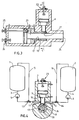
- the new device for producing a flowable reaction mixture from at least two flowable reaction components which react with one another to form solid material or foam starts from storage containers, from which feed lines via metering pumps lead to a mixing head which contains a mixing chamber with an ejection piston guided therein, into which the feed lines are injected by means of injection nozzles open, and from a throttle valve arranged transversely to the mixing chamber in a guide bore and an outlet channel with cleaning pistons.
- the throttle slide is arranged concentrically in the guide bore around the cleaning piston, the guide bore extending in the direction of flow of the mixture beyond the outlet of the mixing chamber and in the mixing phase with the front end of the cleaning piston forming an annular channel which in the Outlet channel merges.
- the mixture stream emerging from the throttle gap formed between the mixing chamber outlet and the throttle slide can not enter directly into the outlet channel, but rather first reaches an annular channel which passes through the wall of the guide bore of the throttle slide to the outside and through the one projecting beyond the throttle slide Cleaning piston is formed.
- the reaction mixture then flows out of this ring channel between the transition edge from the guide bore and the outlet channel to the end edge of the cleaning piston as a sink flow, the outlet channel forming the sink. Due to the concentric arrangement of throttle valve and cleaning piston, this device has a very compact design; Collisions between the pistons and the throttle valve are not possible. It has been shown that no material builds up on the annular shoulder surface at the transition between the guide bore and the outlet channel either, because mixture residues are completely pushed away when the throttle valve is in contact.
- the throttle position of the throttle slide is preferably adjustable.
- the throttle gap or the throttle cross section can be adapted as required. In particular, it can influence the chambering of the mixing chamber.
- the rear dead center position of the cleaning piston is adjustable.
- the height of the outlet gap can be adjusted from the ring channel formed between the wall of the guide bore of the throttle slide and the cleaning piston, as a result of which the outflow speed and the outflow angle from the ring channel, which corresponds to the inflow angle into the outlet channel.
- a special embodiment is also particularly advantageous, according to which the rear dead center position of the discharge piston of the mixing chamber can be adjusted.
- This adjustability allows the mixing chamber volume to be changed or adapted to requirements, which can be of advantage in particular for reaction components which are difficult to mix. It goes without saying that the injection nozzles must remain free during the mixing process.
- a mixing chamber 8 is arranged, in which an ejection piston 9 is guided.
- Injection nozzles 11, 12 are mounted in the housing 10 of the mixing head 7, via which the feed lines 3, 4 open into the mixing chamber 8.
- Switching valves 13, 14 enable the reaction components to be returned via the return lines 15, 16 to the storage containers 1, 2.
- the mixing chamber 8 is followed by a guide bore 17 for a throttle slide 18, which concentrically surrounds a cleaning piston 20 guided in an outlet channel 19. Since the guide bore 17 has a larger diameter than the outlet channel 19 or the cleaning piston 20, there is an annular channel 21 (FIG.
- the ejection piston 9 is assigned an adjusting device 23, which consists of an adjustable stop with which the rear dead center position can be selected.
- the front dead center position is structurally adjusted so that the end face 24 of the ejection piston 9 is flush with the wall of the guide bore 17 and thus bears against the throttle slide 18 (FIGS. 3, 4).
- Both the throttle slide 18 and the cleaning piston 20 are equipped with adjusting devices 25 and 26 for the rear dead center positions consisting of fixable stops.
- the front dead center position of the throttle slide 18 is formed by the shoulder 27 at the transition from the guide bore 17 to the outlet channel 19.
- the front dead center position of the cleaning piston 20 corresponds to the end of the outlet channel 19.
- the mode of operation is as follows:
- the changeover valves 13 and 14 are switched to recirculation.
- the cleaning piston 20, the throttle slide 18 and the exhaust piston 9 are moved to their rear dead center positions, provided that these dead center positions have been previously adjusted to the desired position by means of the adjusting devices 23, 25 and 26.
- the changeover valves 13 and 14 are reversed and the reaction components flow through the inflow nozzles 11 and 12 into the mixing chamber 8, swirl there and pass through the outlet 22 designed as a throttle gap into the annular channel 21.
- the mixture flow divides and flows around via the Throttle slide 18 protruding end of the cleaning piston 20 and flows as a sink flow into the outlet channel 19.
- the changeover valves 13 and 14 switch to return and the ejection piston 9 moves to the front dead center position, empties the mixing chamber 8 and fills it up.
- the throttle slide 18 then moves to its front dead center position, displacing the reaction mixture from the ring channel 21 and filling it. Finally, the discharge channel 19 is emptied with the cleaning piston 20 by moving to its front dead center position.
Landscapes
- Engineering & Computer Science (AREA)
- Mechanical Engineering (AREA)
- Processing And Handling Of Plastics And Other Materials For Molding In General (AREA)
- Injection Moulding Of Plastics Or The Like (AREA)
Applications Claiming Priority (2)
| Application Number | Priority Date | Filing Date | Title |
|---|---|---|---|
| DE4103532 | 1991-02-06 | ||
| DE4103532A DE4103532C1 (fr) | 1991-02-06 | 1991-02-06 |
Publications (2)
| Publication Number | Publication Date |
|---|---|
| EP0498227A1 true EP0498227A1 (fr) | 1992-08-12 |
| EP0498227B1 EP0498227B1 (fr) | 1994-12-14 |
Family
ID=6424468
Family Applications (1)
| Application Number | Title | Priority Date | Filing Date |
|---|---|---|---|
| EP92101124A Expired - Lifetime EP0498227B1 (fr) | 1991-02-06 | 1992-01-24 | Procédé et dispositif pour la fabrication d'un mélange réactif apte à couler à partir d'au moins deux composants réactifs aptes à couler qui réagissent l'un avec l'autre pour former un matériau solide ou mousseux |
Country Status (5)
| Country | Link |
|---|---|
| US (2) | US5143946A (fr) |
| EP (1) | EP0498227B1 (fr) |
| JP (1) | JP3078636B2 (fr) |
| DE (2) | DE4103532C1 (fr) |
| ES (1) | ES2066497T3 (fr) |
Cited By (1)
| Publication number | Priority date | Publication date | Assignee | Title |
|---|---|---|---|---|
| EP0592702A1 (fr) * | 1992-10-12 | 1994-04-20 | Krauss-Maffei Aktiengesellschaft | Procédé et dispositif pour mélanger des composants de matière plastique réactifs |
Families Citing this family (10)
| Publication number | Priority date | Publication date | Assignee | Title |
|---|---|---|---|---|
| DE4211458A1 (de) * | 1992-04-06 | 1993-10-07 | Hennecke Gmbh Maschf | Einrichtung zum Herstellen eines fließfähigen Reaktionsgemisches aus mindestens zwei fließfähigen, miteinander zu Massivstoff oder Schaumstoff reagierenden Reaktionskomponenten |
| DE4446876A1 (de) * | 1994-12-27 | 1996-07-04 | Bayer Ag | Verfahren und Vorrichtung zur Schaumherstellung mittels unter Druck gelöstem Kohlendioxid |
| IT1272896B (it) * | 1995-01-12 | 1997-07-01 | Foaming Techn Cardio Bv | Procedimento ed apparecchiatura per la produzione continua di schiume poliuretaniche pre-espanse |
| GB9806399D0 (en) * | 1998-03-25 | 1998-05-20 | Schoppen Remco | Multi-component mixing and dispensing apparatus |
| RU2158198C1 (ru) * | 1999-03-01 | 2000-10-27 | Открытое акционерное общество "ГАЗ" | Смесительная головка |
| KR20020063933A (ko) * | 2000-01-20 | 2002-08-05 | 크라우스-마파이 쿤스트쉬토프테히닉 게엠베하 | 반응 주조기의 믹싱 헤드용 분사 노즐 |
| DE10014972C1 (de) * | 2000-03-25 | 2001-10-31 | Krauss Maffei Kunststofftech | Umlenk-Mischkopf für eine Reaktionsgiessmaschine |
| ITMI20022336A1 (it) * | 2002-11-05 | 2004-05-06 | Afros Spa | Procedimento ed apparecchiatura di miscelazione con |
| ITMI20110892A1 (it) | 2011-05-19 | 2012-11-20 | Afros Spa | Apparecchiatura autopulente di miscelazione ad alta pressione per materiale composito |
| DE102014001461A1 (de) | 2014-02-05 | 2015-08-06 | Hennecke Gmbh | Verfahren zum Herstellen eines Formteils aus Polyurethan |
Citations (6)
| Publication number | Priority date | Publication date | Assignee | Title |
|---|---|---|---|---|
| DE2065057A1 (en) * | 1970-02-20 | 1972-03-30 | Krauss Maffei Ag | Synth resin component mixer |
| FR2428520A1 (fr) * | 1978-06-14 | 1980-01-11 | Krauss Maffei Ag | Dispositif (tete de melange) pour produire, a partir d'au moins deux constituants generateurs d'une matiere plastique, un melange reactif |
| EP0037523A1 (fr) * | 1980-04-03 | 1981-10-14 | Bayer Ag | Dispositif permettant de former un mélange pour la fabrication d'une matière compacte ou mousse, composé d'au moins deux fluides réagissant entre eux et de matière de charge |
| EP0079510A1 (fr) * | 1981-11-12 | 1983-05-25 | Krauss-Maffei Aktiengesellschaft | Tête de mélange |
| DE3313042A1 (de) * | 1983-04-12 | 1984-10-18 | Krauss-Maffei AG, 8000 München | Vorrichtung zum zuleiten eines insbesondere chemisch reaktionsfaehigen kunststoffgemisches zu einer form (mischkopf) |
| EP0261368A2 (fr) * | 1986-09-25 | 1988-03-30 | Afros S.P.A. | Dispositif de mélange à haute pression |
Family Cites Families (8)
| Publication number | Priority date | Publication date | Assignee | Title |
|---|---|---|---|---|
| CA943721A (en) * | 1970-02-20 | 1974-03-19 | Krauss-Maffei Aktiengesellschaft | Device for feeding flowable material to a cavity |
| DE2327269C3 (de) * | 1973-05-29 | 1981-04-09 | Krauss-Maffei AG, 8000 München | Vorrichtung zum Zuleiten eines insbesondere chemischreaktionsfähigen Kunststoffgemisches zu einer Form |
| DE2612812C3 (de) * | 1976-03-25 | 1983-05-26 | Bayer Ag, 5090 Leverkusen | Mischkopf zum Vermischen mindestens zweier bei ihrer Reaktion Schaumstoff bildender Komponenten |
| DE2933553A1 (de) * | 1979-08-18 | 1981-03-26 | Bayer Ag, 51373 Leverkusen | Verfahren und einrichtung zum herstellen von formteilen aus einem mehrkomponentenreaktionsgemisch |
| DE2936223A1 (de) * | 1979-09-07 | 1981-03-19 | Bayer Ag, 5090 Leverkusen | Verfahren und einrichtung zum herstellen eines reaktionsgemisches aus fliessfaehigen, schaum- oder massivstoff bildenden komponenten |
| DE3128913A1 (de) * | 1981-07-22 | 1983-02-10 | Maschinenfabrik Hennecke Gmbh, 5090 Leverkusen | Verfahren und einrichtung zum herstellen eines fliessfaehigen reaktionsgemisches aus mindestens zwei fliessfaehigen, miteinander zu massivstoff oder schaumstoff reagierenden reaktionskomponenten |
| IT1196275B (it) * | 1984-10-01 | 1988-11-16 | Afros Spa | Testa miscelatrice a camera mobile |
| DE3736299A1 (de) * | 1987-10-27 | 1989-05-11 | Elastogran Polyurethane Gmbh | Hochdruckmischvorrichtung zum mischen von mehrkomponentenkunststoffen, insbesondere polyurethan |
-
1991
- 1991-02-06 DE DE4103532A patent/DE4103532C1/de not_active Expired - Fee Related
-
1992
- 1992-01-24 EP EP92101124A patent/EP0498227B1/fr not_active Expired - Lifetime
- 1992-01-24 DE DE59200925T patent/DE59200925D1/de not_active Expired - Fee Related
- 1992-01-24 ES ES92101124T patent/ES2066497T3/es not_active Expired - Lifetime
- 1992-01-31 US US07/830,164 patent/US5143946A/en not_active Expired - Lifetime
- 1992-02-04 JP JP04047599A patent/JP3078636B2/ja not_active Expired - Fee Related
- 1992-06-08 US US07/895,485 patent/US5443797A/en not_active Expired - Lifetime
Patent Citations (6)
| Publication number | Priority date | Publication date | Assignee | Title |
|---|---|---|---|---|
| DE2065057A1 (en) * | 1970-02-20 | 1972-03-30 | Krauss Maffei Ag | Synth resin component mixer |
| FR2428520A1 (fr) * | 1978-06-14 | 1980-01-11 | Krauss Maffei Ag | Dispositif (tete de melange) pour produire, a partir d'au moins deux constituants generateurs d'une matiere plastique, un melange reactif |
| EP0037523A1 (fr) * | 1980-04-03 | 1981-10-14 | Bayer Ag | Dispositif permettant de former un mélange pour la fabrication d'une matière compacte ou mousse, composé d'au moins deux fluides réagissant entre eux et de matière de charge |
| EP0079510A1 (fr) * | 1981-11-12 | 1983-05-25 | Krauss-Maffei Aktiengesellschaft | Tête de mélange |
| DE3313042A1 (de) * | 1983-04-12 | 1984-10-18 | Krauss-Maffei AG, 8000 München | Vorrichtung zum zuleiten eines insbesondere chemisch reaktionsfaehigen kunststoffgemisches zu einer form (mischkopf) |
| EP0261368A2 (fr) * | 1986-09-25 | 1988-03-30 | Afros S.P.A. | Dispositif de mélange à haute pression |
Non-Patent Citations (1)
| Title |
|---|
| PATENT ABSTRACTS OF JAPAN vol. 12, no. 338 (C-527)(3185) 12. September 1988 & JP-A-63 097 218 ( POLYURETHAN ) * |
Cited By (1)
| Publication number | Priority date | Publication date | Assignee | Title |
|---|---|---|---|---|
| EP0592702A1 (fr) * | 1992-10-12 | 1994-04-20 | Krauss-Maffei Aktiengesellschaft | Procédé et dispositif pour mélanger des composants de matière plastique réactifs |
Also Published As
| Publication number | Publication date |
|---|---|
| ES2066497T3 (es) | 1995-03-01 |
| EP0498227B1 (fr) | 1994-12-14 |
| DE4103532C1 (fr) | 1992-09-03 |
| DE59200925D1 (de) | 1995-01-26 |
| JP3078636B2 (ja) | 2000-08-21 |
| US5143946A (en) | 1992-09-01 |
| US5443797A (en) | 1995-08-22 |
| JPH04334406A (ja) | 1992-11-20 |
Similar Documents
| Publication | Publication Date | Title |
|---|---|---|
| EP0135798B1 (fr) | Buse multiple pour réunir au moins deux réactants fluides pour produire un mélange réactionnel fluide formant, par réaction, de la matière plastique, en particulier de la matière plastique alvéolaire | |
| DE3688036T2 (de) | Hochdruckmischkopf fuer reaktive bestandteile. | |
| DE3734164C3 (de) | Verfahren zum Spritzgießen von Formteilen aus thermoplastischen Kunststoffen sowie Vorrichtung zur Durchführung des Verfahrens | |
| DE2612812A1 (de) | Mischkopf zum vermischen mindestens zweier bei ihrer reaktion schaumstoff bildender komponenten | |
| EP0099045B1 (fr) | Méthode et tête de mélange pour la fabrication d'un mélange ayant au moins deux composants réactifs pouvant couler et formant une matière plastique | |
| DE2907938A1 (de) | Vorrichtung fuer die mischung und verspritzung von miteinander reagierenden fluessigen komponenten fuer die kunststoffteileformung | |
| DE2645937B2 (de) | Hochdruck-Injektionsmischkopf für Mehrkomponentenkunststoffe, insbesondere Polyurethan | |
| EP0024608A1 (fr) | Procédé et dispositif de production de pièces moulées à partir d'un mélange fluide réactionnel formant une matière pleine ou expansée | |
| DE3014175A1 (de) | Verfahren und vorrichtung zum einspritzmischen und -abgeben fuer hochgeschwindigkeitsreaktionen | |
| EP0143196A2 (fr) | Tête de mixeur pour la fabrication d'un mélange capable de produire une réaction chimique et consistant en au moins deux composants de plastique | |
| EP0498227B1 (fr) | Procédé et dispositif pour la fabrication d'un mélange réactif apte à couler à partir d'au moins deux composants réactifs aptes à couler qui réagissent l'un avec l'autre pour former un matériau solide ou mousseux | |
| EP0070486B1 (fr) | Procédé et dispositif pour produire un mélange réactionnel de composants fluides au moins avec deux composantes de réaction capables de couler, réagissantes ensemble pour devenir une matière homogène ou de mousse | |
| EP0187360B1 (fr) | Ensemble mélangeur-moule pour produire des articles d'un mélange réactif à partir d'au moins deux constituants réactifs fluides | |
| DE2847504A1 (de) | Mischkopf zum mischen von wenigstens zwei fliessfaehigen materialkomponenten | |
| EP0564908B1 (fr) | Dispositif pour mélanger des composants de réaction réagissant entre eux | |
| DE69311037T2 (de) | Spritzgiesspresse und deren Verwendung | |
| DE4009465C2 (de) | Vorrichtung zum mischen von wenigstens zwei reaktiven kunststoffkomponenten | |
| DE4104647A1 (de) | Mischvorrichtung zur verarbeitung fluessiger mehrkomponenten-kunststoffe, insbesondere polyurethan | |
| DE102007045439B3 (de) | Vorrichtung zum Durchmischen oder Filtern von Schmelze an einer Spritzgießmaschine | |
| EP0249054B1 (fr) | Dispositif pour la fabrication d'un mélange réactif de composants pouvant être coulés pour former un matériau en plastic massif ou en mousse de plastique | |
| EP0355538B1 (fr) | Procédé et dispositif pour la fabrication de mélanges réactifs aptes à couler pour former des matières plastiques à multicomposants | |
| EP0070487B1 (fr) | Dispositif pour produire un mélange réactionnel de composants fluides au moins avec deux composantes de réaction capables de couler, réagissantes ensemble pour devenir une matière homogène ou de mousse | |
| DE3239551A1 (de) | Vorrichtung zum zuleiten eines insbesondere chemisch reaktionsfaehigen kunststoffgemisches zu einer form (mischkopf) | |
| EP0093356B1 (fr) | Dispositif mélangeur pour matières plastiques à composants multiples | |
| DE19849797A1 (de) | Injektor und Injektionsverfahren, insbesondere für thermoplastisches Material |
Legal Events
| Date | Code | Title | Description |
|---|---|---|---|
| PUAI | Public reference made under article 153(3) epc to a published international application that has entered the european phase |
Free format text: ORIGINAL CODE: 0009012 |
|
| AK | Designated contracting states |
Kind code of ref document: A1 Designated state(s): DE ES FR GB IT NL |
|
| 17P | Request for examination filed |
Effective date: 19920910 |
|
| 17Q | First examination report despatched |
Effective date: 19940530 |
|
| GRAA | (expected) grant |
Free format text: ORIGINAL CODE: 0009210 |
|
| AK | Designated contracting states |
Kind code of ref document: B1 Designated state(s): DE ES FR GB IT NL |
|
| ITF | It: translation for a ep patent filed | ||
| REF | Corresponds to: |
Ref document number: 59200925 Country of ref document: DE Date of ref document: 19950126 |
|
| REG | Reference to a national code |
Ref country code: ES Ref legal event code: FG2A Ref document number: 2066497 Country of ref document: ES Kind code of ref document: T3 |
|
| ET | Fr: translation filed | ||
| GBT | Gb: translation of ep patent filed (gb section 77(6)(a)/1977) |
Effective date: 19950224 |
|
| PLBE | No opposition filed within time limit |
Free format text: ORIGINAL CODE: 0009261 |
|
| STAA | Information on the status of an ep patent application or granted ep patent |
Free format text: STATUS: NO OPPOSITION FILED WITHIN TIME LIMIT |
|
| 26N | No opposition filed | ||
| PGFP | Annual fee paid to national office [announced via postgrant information from national office to epo] |
Ref country code: NL Payment date: 19960131 Year of fee payment: 5 |
|
| PG25 | Lapsed in a contracting state [announced via postgrant information from national office to epo] |
Ref country code: NL Effective date: 19970801 |
|
| NLV4 | Nl: lapsed or anulled due to non-payment of the annual fee |
Effective date: 19970801 |
|
| REG | Reference to a national code |
Ref country code: GB Ref legal event code: IF02 |
|
| PG25 | Lapsed in a contracting state [announced via postgrant information from national office to epo] |
Ref country code: IT Free format text: LAPSE BECAUSE OF NON-PAYMENT OF DUE FEES;WARNING: LAPSES OF ITALIAN PATENTS WITH EFFECTIVE DATE BEFORE 2007 MAY HAVE OCCURRED AT ANY TIME BEFORE 2007. THE CORRECT EFFECTIVE DATE MAY BE DIFFERENT FROM THE ONE RECORDED. Effective date: 20050124 |
|
| PGFP | Annual fee paid to national office [announced via postgrant information from national office to epo] |
Ref country code: ES Payment date: 20080218 Year of fee payment: 17 |
|
| PGFP | Annual fee paid to national office [announced via postgrant information from national office to epo] |
Ref country code: GB Payment date: 20080123 Year of fee payment: 17 Ref country code: DE Payment date: 20080108 Year of fee payment: 17 |
|
| PGFP | Annual fee paid to national office [announced via postgrant information from national office to epo] |
Ref country code: FR Payment date: 20080108 Year of fee payment: 17 |
|
| GBPC | Gb: european patent ceased through non-payment of renewal fee |
Effective date: 20090124 |
|
| PG25 | Lapsed in a contracting state [announced via postgrant information from national office to epo] |
Ref country code: DE Free format text: LAPSE BECAUSE OF NON-PAYMENT OF DUE FEES Effective date: 20090801 |
|
| REG | Reference to a national code |
Ref country code: FR Ref legal event code: ST Effective date: 20091030 |
|
| PG25 | Lapsed in a contracting state [announced via postgrant information from national office to epo] |
Ref country code: GB Free format text: LAPSE BECAUSE OF NON-PAYMENT OF DUE FEES Effective date: 20090124 |
|
| REG | Reference to a national code |
Ref country code: ES Ref legal event code: FD2A Effective date: 20090126 |
|
| PG25 | Lapsed in a contracting state [announced via postgrant information from national office to epo] |
Ref country code: ES Free format text: LAPSE BECAUSE OF NON-PAYMENT OF DUE FEES Effective date: 20090126 Ref country code: FR Free format text: LAPSE BECAUSE OF NON-PAYMENT OF DUE FEES Effective date: 20090202 |
|
| PGFP | Annual fee paid to national office [announced via postgrant information from national office to epo] |
Ref country code: IT Payment date: 20080128 Year of fee payment: 17 |
|
| PGRI | Patent reinstated in contracting state [announced from national office to epo] |
Ref country code: IT Effective date: 20091201 |
|
| PGRI | Patent reinstated in contracting state [announced from national office to epo] |
Ref country code: IT Effective date: 20091201 |