EP0498376A1 - Seringue jetable autodétruisante - Google Patents
Seringue jetable autodétruisante Download PDFInfo
- Publication number
- EP0498376A1 EP0498376A1 EP92101835A EP92101835A EP0498376A1 EP 0498376 A1 EP0498376 A1 EP 0498376A1 EP 92101835 A EP92101835 A EP 92101835A EP 92101835 A EP92101835 A EP 92101835A EP 0498376 A1 EP0498376 A1 EP 0498376A1
- Authority
- EP
- European Patent Office
- Prior art keywords
- piston
- section
- chamber
- syringe according
- syringe
- Prior art date
- Legal status (The legal status is an assumption and is not a legal conclusion. Google has not performed a legal analysis and makes no representation as to the accuracy of the status listed.)
- Withdrawn
Links
- 230000001066 destructive effect Effects 0.000 title 1
- 239000012528 membrane Substances 0.000 claims abstract description 30
- 239000007788 liquid Substances 0.000 claims description 12
- 230000008878 coupling Effects 0.000 claims description 6
- 238000010168 coupling process Methods 0.000 claims description 6
- 238000005859 coupling reaction Methods 0.000 claims description 6
- 230000003313 weakening effect Effects 0.000 claims description 3
- 238000002347 injection Methods 0.000 description 5
- 239000007924 injection Substances 0.000 description 5
- 230000005540 biological transmission Effects 0.000 description 4
- 201000010099 disease Diseases 0.000 description 3
- 208000037265 diseases, disorders, signs and symptoms Diseases 0.000 description 3
- 208000030507 AIDS Diseases 0.000 description 2
- 239000003795 chemical substances by application Substances 0.000 description 2
- 208000006454 hepatitis Diseases 0.000 description 2
- 231100000283 hepatitis Toxicity 0.000 description 2
- 238000007142 ring opening reaction Methods 0.000 description 2
- 230000008719 thickening Effects 0.000 description 2
- 238000002255 vaccination Methods 0.000 description 2
- 208000035473 Communicable disease Diseases 0.000 description 1
- 230000000694 effects Effects 0.000 description 1
- 208000015181 infectious disease Diseases 0.000 description 1
- 239000002054 inoculum Substances 0.000 description 1
- 244000052769 pathogen Species 0.000 description 1
- 230000000717 retained effect Effects 0.000 description 1
- 239000000126 substance Substances 0.000 description 1
Images

Classifications
-
- A—HUMAN NECESSITIES
- A61—MEDICAL OR VETERINARY SCIENCE; HYGIENE
- A61M—DEVICES FOR INTRODUCING MEDIA INTO, OR ONTO, THE BODY; DEVICES FOR TRANSDUCING BODY MEDIA OR FOR TAKING MEDIA FROM THE BODY; DEVICES FOR PRODUCING OR ENDING SLEEP OR STUPOR
- A61M5/00—Devices for bringing media into the body in a subcutaneous, intra-vascular or intramuscular way; Accessories therefor, e.g. filling or cleaning devices, arm-rests
- A61M5/178—Syringes
- A61M5/31—Details
- A61M5/32—Needles; Details of needles pertaining to their connection with syringe or hub; Accessories for bringing the needle into, or holding the needle on, the body; Devices for protection of needles
- A61M5/3205—Apparatus for removing or disposing of used needles or syringes, e.g. containers; Means for protection against accidental injuries from used needles
- A61M5/321—Means for protection against accidental injuries by used needles
- A61M5/322—Retractable needles, i.e. disconnected from and withdrawn into the syringe barrel by the piston
-
- A—HUMAN NECESSITIES
- A61—MEDICAL OR VETERINARY SCIENCE; HYGIENE
- A61M—DEVICES FOR INTRODUCING MEDIA INTO, OR ONTO, THE BODY; DEVICES FOR TRANSDUCING BODY MEDIA OR FOR TAKING MEDIA FROM THE BODY; DEVICES FOR PRODUCING OR ENDING SLEEP OR STUPOR
- A61M5/00—Devices for bringing media into the body in a subcutaneous, intra-vascular or intramuscular way; Accessories therefor, e.g. filling or cleaning devices, arm-rests
- A61M5/50—Devices for bringing media into the body in a subcutaneous, intra-vascular or intramuscular way; Accessories therefor, e.g. filling or cleaning devices, arm-rests having means for preventing re-use, or for indicating if defective, used, tampered with or unsterile
- A61M5/508—Means for preventing re-use by disrupting the piston seal, e.g. by puncturing
-
- A—HUMAN NECESSITIES
- A61—MEDICAL OR VETERINARY SCIENCE; HYGIENE
- A61M—DEVICES FOR INTRODUCING MEDIA INTO, OR ONTO, THE BODY; DEVICES FOR TRANSDUCING BODY MEDIA OR FOR TAKING MEDIA FROM THE BODY; DEVICES FOR PRODUCING OR ENDING SLEEP OR STUPOR
- A61M5/00—Devices for bringing media into the body in a subcutaneous, intra-vascular or intramuscular way; Accessories therefor, e.g. filling or cleaning devices, arm-rests
- A61M5/178—Syringes
- A61M5/31—Details
- A61M2005/3101—Leak prevention means for proximal end of syringes, i.e. syringe end opposite to needle mounting end
-
- A—HUMAN NECESSITIES
- A61—MEDICAL OR VETERINARY SCIENCE; HYGIENE
- A61M—DEVICES FOR INTRODUCING MEDIA INTO, OR ONTO, THE BODY; DEVICES FOR TRANSDUCING BODY MEDIA OR FOR TAKING MEDIA FROM THE BODY; DEVICES FOR PRODUCING OR ENDING SLEEP OR STUPOR
- A61M5/00—Devices for bringing media into the body in a subcutaneous, intra-vascular or intramuscular way; Accessories therefor, e.g. filling or cleaning devices, arm-rests
- A61M5/178—Syringes
- A61M5/31—Details
- A61M5/32—Needles; Details of needles pertaining to their connection with syringe or hub; Accessories for bringing the needle into, or holding the needle on, the body; Devices for protection of needles
- A61M5/3205—Apparatus for removing or disposing of used needles or syringes, e.g. containers; Means for protection against accidental injuries from used needles
- A61M5/321—Means for protection against accidental injuries by used needles
- A61M5/322—Retractable needles, i.e. disconnected from and withdrawn into the syringe barrel by the piston
- A61M5/3221—Constructional features thereof, e.g. to improve manipulation or functioning
- A61M2005/3231—Proximal end of needle captured or embedded inside piston head, e.g. by friction or hooks
-
- A—HUMAN NECESSITIES
- A61—MEDICAL OR VETERINARY SCIENCE; HYGIENE
- A61M—DEVICES FOR INTRODUCING MEDIA INTO, OR ONTO, THE BODY; DEVICES FOR TRANSDUCING BODY MEDIA OR FOR TAKING MEDIA FROM THE BODY; DEVICES FOR PRODUCING OR ENDING SLEEP OR STUPOR
- A61M5/00—Devices for bringing media into the body in a subcutaneous, intra-vascular or intramuscular way; Accessories therefor, e.g. filling or cleaning devices, arm-rests
- A61M5/178—Syringes
- A61M5/31—Details
- A61M5/32—Needles; Details of needles pertaining to their connection with syringe or hub; Accessories for bringing the needle into, or holding the needle on, the body; Devices for protection of needles
- A61M5/34—Constructions for connecting the needle, e.g. to syringe nozzle or needle hub
- A61M2005/342—Off-center needles, i.e. needle connections not being coaxial with the longitudinal symmetry axis of syringe barrel
-
- A—HUMAN NECESSITIES
- A61—MEDICAL OR VETERINARY SCIENCE; HYGIENE
- A61M—DEVICES FOR INTRODUCING MEDIA INTO, OR ONTO, THE BODY; DEVICES FOR TRANSDUCING BODY MEDIA OR FOR TAKING MEDIA FROM THE BODY; DEVICES FOR PRODUCING OR ENDING SLEEP OR STUPOR
- A61M5/00—Devices for bringing media into the body in a subcutaneous, intra-vascular or intramuscular way; Accessories therefor, e.g. filling or cleaning devices, arm-rests
- A61M5/178—Syringes
- A61M5/31—Details
- A61M5/32—Needles; Details of needles pertaining to their connection with syringe or hub; Accessories for bringing the needle into, or holding the needle on, the body; Devices for protection of needles
- A61M5/34—Constructions for connecting the needle, e.g. to syringe nozzle or needle hub
- A61M5/347—Constructions for connecting the needle, e.g. to syringe nozzle or needle hub rotatable, e.g. bayonet or screw
Definitions
- the invention relates to a self-destructive disposable safety syringe according to the preamble of claim 1.
- Syringes are known which claim to offer the safety of single use to prevent the possible transmission of diseases such as AIDS.
- these syringes are either very complicated and therefore expensive, or it is necessary for the person who uses them to take a certain special action after the syringe which renders the syringe unusable.
- Carelessness, negligence or even the intention to use the same syringe a second time negate the safety effect of these syringes, so that they are still considered to be very unreliable.
- the object of the invention is to provide a self-destructing disposable safety syringe with which two uses are certainly prevented, so that any transmission of contagious diseases or infections is excluded.
- the plunger is destroyed, so that it is not possible to aspirate any liquid a second time when trying to refill the syringe.
- a needle is provided at the front end of the cylindrical chamber. Inside the chamber a piston is slidably guided, the piston rod is extended outwards.
- the peculiarity of the present invention is that a membrane is provided on the end face of the piston, which is pierced by a pointed element which is arranged at the bottom of the cylindrical chamber when the piston reaches the bottom of the cylindrical chamber. This makes it impossible to use the syringe twice.
- the pointed element can be a protruding part integrated into the body of the syringe at the bottom of the cylindrical chamber or the rear end of the syringe needle. In the latter case, the needle continues inside the cylindrical chamber where it has the pointed end with which the membrane is pierced at the end of the first administration.
- the membrane can consist of a cap which is arranged between a part projecting on the end face of the piston and a ring.
- An O-ring or similar seal is arranged on the circumference of this ring in order to seal the piston against the inner wall of the chamber.
- the membrane can also consist of a disc-shaped body which is adhesively bonded to the end face of the piston or is otherwise adhesively attached, so that it completely or partially covers the end face of the piston.
- the piston has an opening behind the membrane. This can be designed as a longitudinal opening and can be provided with radial branches which open into the second chamber section.
- the piston rod can be hollow and provided with radial openings around which to connect the second chamber section to the environment.
- the free end of the piston rod can have some ring-shaped or screw-shaped thickenings on the outside, similar to a thread, and thereby form a non-slip surface when filling the syringe.
- the needle can be pulled out of the syringe housing or can be firmly connected to the syringe housing. It is preferably protected by a cover, which cover can be connected to the front end of the syringe housing.
- the housing of the cylindrical chamber has an incision into which a bush engages, which serves as a piston guide and as a pull-out protection for the piston, thereby preventing reuse.
- the piston has a threaded pin on its face, on the face of which the membrane is provided.
- the membrane can be formed by a "weakening" of the end wall of the threaded pin, i.e. the threaded pin and the membrane can be formed in one piece.
- the needle can be connected to a socket, which has a thread on its rear part for coupling to the threaded pin, which extends coaxially from the piston end face to the socket.
- the sleeve that holds the needle is held in a neck at the front end of the syringe barrel by a thread attached to the neck. If, by rotating the piston rod, the threaded pin of the piston has been screwed into the socket up to the stop of the piston, the socket is unscrewed from the neck of the syringe as rotation continues.
- the piston can have an extension with an annular incision or an annular extension on its rear side. Furthermore, a thread can be attached to the rear of the piston or this extension in order to screw the piston rod, which is likewise threaded at its front end.
- a guide bush for the piston rod is arranged at the rear end of the syringe.
- the guide bushing can have one or more protrusions for hooking the aforementioned annular incision to the rear of the piston.
- the plunger In this position, the plunger is located at the rear end of the chamber, and the plunger rod can be removed by unscrewing, which means that the thrown-away syringe takes up less space and an accidental axial thrust on the plunger rod does not lead to the needle escaping from the syringe housing.
- the pin provided on the end face of the piston and / or the recess of the bushing in which the pin engages can be provided on the surface with some oblique annular grooves in order to connect the piston to the bushing by axial pressure. These annular oblique grooves can therefore replace the corresponding threads mentioned above, which simplifies the coupling between the bushing and the piston.
- a disc-shaped seal is arranged between the socket and the front end of the syringe body. After performing the specified operations, rotating and then retracting the piston rod, due to its elastic nature, it automatically closes the opening through which the needle extends before being drawn into the chamber. In this way, the chamber is hermetically sealed from the outside, so that no pathogens or other harmful substances can escape from the inside of the syringe.
- the cover or cap which can be integrally connected to the syringe housing and protects the needle, can be closed at its front end by a stopper.
- a stopper is particularly useful when the syringe is used for vaccinations, since in general the agent to be injected is already delivered in the syringe.
- a lateral opening can be provided which forms a second outlet for the liquid to be sprayed, the liquid escaping through this lateral opening especially when the pointed element pierces the membrane Has.
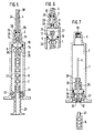
- the syringe has a syringe housing 1 in which there is a cylindrical chamber 2.
- the syringe housing 1 is provided at its front end with a taper 3 through which the injection needle 4 is inserted, which extends into the chamber 2.
- a piston 5 is slidably guided, which is provided on its rear side with a piston rod 6, which extends outwards from the rear end of the syringe housing 1.
- the piston 2 If the piston 2 is between its two end positions at the front or rear end of the chamber 2, it separates the chamber 2 into a first, front section 7, facing the needle 4, in which the injection liquid is located, and a second, rear Section 8 through which the piston rod 6 extends and which contains no liquid, that is to say is filled with air.
- the piston 5 On its end face 9 facing the needle 4 or the front chamber section, the piston 5 is provided with an opening 10 which is formed by a longitudinal channel 11 which extends in the axial direction and extends into an extension 12 on the rear side of the piston 5.
- the extension 12 is cross-shaped in cross section, the diameter of the longitudinal channel 11 is greater than the thickness of the arms of the cross, so that lateral longitudinal openings 13 are formed in the corners between two adjacent arms, which with the rear portion 8 of the chamber 2, so communicate with the air contained therein.
- the opening 10 on the end face 9 of the piston is closed by a membrane 14.
- the rear end of the needle 4, which projects into the chamber 2 or the front section 7, is provided with a tip.
- a pointed element 15 is formed on the front bottom 16 of the chamber 2.
- the pointed element 15 lies exactly opposite the opening 10 in the direction of movement of the piston 2, i.e., according to FIG. 1, both the opening 10 and the pointed element 15 lie in the longitudinal central axis of the syringe.
- the piston 5 consists of a first annular section 17 with a ring opening widening towards the rear and a second section 18, which tapers forward and extends from the piston rod 6 into the ring opening of the ring-shaped section 17, on which the Extension 12 is arranged with the longitudinal openings 13.
- the membrane 14 is cap-shaped and slipped over the second section 18, that is to say clamped between the two sections 17 and 18.
- an O-ring 19 or the like is in a groove. Seal arranged.
- the membrane 14 is designed as a disc, it rests on the piston 2 and covers its entire end face 9.
- radial bores 20 extend from the longitudinal channel 11 into the chamber 2 or into the rear chamber section 8.
- the piston rod 6 can e.g. cylindrical and the longitudinal channel 11 may be formed by a longitudinal bore in the piston rod 6.
- the pointed element 15, which pierces the membrane 14, is formed by a projection provided on the bottom 14 of the chamber 2, which is opposite the opening 10, that is to say how it lies in the longitudinal central axis of the syringe.
- the injection needle 4 is arranged eccentrically in this embodiment.
- the membrane 14 is fastened in a recess on the end face 9 of the piston 5.
- the piston rod 6, which adjoins the extension 12 has a longitudinal channel 21 which opens into the open at the rear end of the piston rod 6.
- the piston rod 6 is also provided with radial openings 22 so that the rear section 8 of the chamber 2 communicates with the surroundings.
- the front section 7 of the chamber 2 also communicates with the environment, so that the syringe is unusable.
- the piston rod 6 has ring-shaped or screw-shaped thickenings 28 in order to form a non-slip surface, which makes filling the syringe safer.
- the injection needle 4 is fixed to the syringe housing 1 or can be pushed out. It is protected by a cover or cap 24 which extends to the front end of the syringe housing 1.
- the syringe housing 4 has an annular groove on the inside, in which a bushing 25 is arranged, which serves as a guide and seal for the piston rod 6 and as a pull-out protection for the piston 5. So that the piston 5 can not be pulled out of the syringe housing 1, so that the syringe housing 1 can not be used again, that is, with a new piston.
- the piston 5 closes the front section 7 from the rear section 8 of the chamber 2 with the opening 10 closed by the membrane 14, so that the liquid which is to be sprayed can be sucked in as in a conventional syringe.
- the syringe is filled, it is administered to the patient as usual.
- the pointed element 15 pierces the membrane 14 at the opening 10. It is therefore no longer possible to refill the syringe. That is, it is unusable so that risks associated with using the syringe twice, such as the transmission of diseases such as AIDS, hepatitis, etc., are avoided.
- the piston 5 has on its end face 9 a pin 25 through which the longitudinal channel 11 extends.
- the opening 10 at the front end of the longitudinal channel 11 is in turn closed by a membrane 11, which, however, is formed in one piece with the pin 25 or the piston 5 in this embodiment.
- the needle 4 is initially protected by a sleeve-shaped cover 24, which, however, is formed in one piece with the syringe housing 1.
- the cover 24 can be pulled off by breaking off the annular weakening 26 at its base.
- the pin 25 on the plunger 5 is provided with a thread 27 and can thus be screwed into a bushing 28 which is arranged in the taper 3 in the form of a neck at the front end of the syringe housing 1.
- the bushing 28 is provided with an external thread 29 which engages in a corresponding internal thread in the neck section 3.
- the external thread 27 on the pin 25 and the external thread 29 on the bushing 28 run in the opposite direction; by rotating the piston rod 6 and thus the pin 25, the pin 25 can be coupled to the bushing 28 arranged in the neck section 3, which in turn is unscrewed from the neck section 3 by rotating in the same direction of rotation by the neck section 3.
- the thread 27 on the pin 25 can engage in an internal thread in the socket 28.
- the socket 28 can have annular grooves 31 in order to clamp the pin 25 in the socket 28 by axial pressure.
- a disk-shaped seal 30 is attached between the socket 28 and the front end of the neck section 3 of the syringe housing 1.
- the piston rod 6 is rotated so that the pin 25 on the end face 9 of the piston 5 is screwed into the rear receptacle of the socket 28 with the grooves 31 becomes.
- the socket 28 is unscrewed from the neck portion 3 of the syringe housing 1, so that when the piston rod 6 is withdrawn, the needle 4 fastened in the socket 28 is moved into the chamber 2.
- the annular projection 36 on the bushing 37 also engages in the groove or constriction 34 on the rear extension 12 of the piston 5, whereby this is clamped in this position.
- the needle 4 is held in the chamber 2, that is to say inside the syringe housing 1, so that it is no longer accessible from the outside. Due to its elastic nature, the disk-shaped seal 30 automatically closes the opening through which the needle 4 previously extended. In this way, the chamber 2 with the needle 4 arranged therein is hermetically sealed from the environment.
- the coupling of the plunger 5 to the socket 28 takes place through the oblique annular grooves 31, the coupling occurs automatically at the end of the administration of the syringe, i.e. when the pin 25 reaches the socket 28.
- the piston rod 6 can be unscrewed from the piston 6 by unscrewing the threads 32 and 33. This means that the thrown away syringe takes up less space. In addition, there can be no unwanted axial thrust, which in extreme cases would cause the needle 4 to be removed again. Also for reasons of safety and to reduce the space requirement, the syringe is advantageously sold with the piston rod 6 unscrewed.
- a stopper 38 is attached to the end of the cover 24 to prevent that Inoculant exits through the needle 4.
- the needle 4 has at the rear end, at which the pointed element 15 is located, a lateral opening 39, which forms a second outlet for the liquid to be sprayed, and is particularly necessary when the pointed element 15 has penetrated into the membrane 14 is to administer the rest of the liquid. That is, the opening 39 ensures that the liquid escapes until the end of the administration. is particularly necessary when the pointed element 15 has penetrated into the membrane 14 in order to administer the rest of the liquid. That is, the opening 39 ensures that the liquid escapes until the end of the administration.
Landscapes
- Health & Medical Sciences (AREA)
- Engineering & Computer Science (AREA)
- Hematology (AREA)
- Anesthesiology (AREA)
- Biomedical Technology (AREA)
- Heart & Thoracic Surgery (AREA)
- Vascular Medicine (AREA)
- Life Sciences & Earth Sciences (AREA)
- Animal Behavior & Ethology (AREA)
- General Health & Medical Sciences (AREA)
- Public Health (AREA)
- Veterinary Medicine (AREA)
- Environmental & Geological Engineering (AREA)
- Infusion, Injection, And Reservoir Apparatuses (AREA)
Applications Claiming Priority (2)
| Application Number | Priority Date | Filing Date | Title |
|---|---|---|---|
| ES9100283 | 1991-02-04 | ||
| ES9100283A ES2031754A6 (es) | 1991-02-04 | 1991-02-04 | Mejoras introducidas en el objeto de la patente principal n{ 9002681/0por: jeringuilla de seguridad autodestruible de un solo uso. |
Publications (1)
| Publication Number | Publication Date |
|---|---|
| EP0498376A1 true EP0498376A1 (fr) | 1992-08-12 |
Family
ID=8271064
Family Applications (1)
| Application Number | Title | Priority Date | Filing Date |
|---|---|---|---|
| EP92101835A Withdrawn EP0498376A1 (fr) | 1991-02-04 | 1992-02-04 | Seringue jetable autodétruisante |
Country Status (2)
| Country | Link |
|---|---|
| EP (1) | EP0498376A1 (fr) |
| ES (1) | ES2031754A6 (fr) |
Cited By (11)
| Publication number | Priority date | Publication date | Assignee | Title |
|---|---|---|---|---|
| WO1999048543A3 (fr) * | 1998-03-20 | 1999-11-11 | Mauro Ghigo | Seringue a securite |
| RU2197278C2 (ru) * | 2000-08-25 | 2003-01-27 | Дикалов Борис Афанасьевич | Шприц |
| EP1281412A1 (fr) * | 2001-03-07 | 2003-02-05 | Eurochina Farma S.L. | Seringue non réutilisable |
| RU2203689C2 (ru) * | 1999-10-15 | 2003-05-10 | Назаров Юлий Васильевич | Одноразовый шприц |
| WO2006047810A1 (fr) * | 2004-11-04 | 2006-05-11 | Global Medisafe Holdings Pty Limited | Seringue de securite retractable a changement d’aiguille |
| WO2007028190A1 (fr) * | 2005-09-06 | 2007-03-15 | Global Medisafe Holdings Limited | Seringue de sécurité jetable à aiguille rétractable |
| US7806860B2 (en) | 2005-11-15 | 2010-10-05 | Global Medisafe Holdings Limited | Safety syringe with plunger locking means |
| EP1894589A4 (fr) * | 2005-06-09 | 2012-01-11 | Ying Jishui | Seringue jetable non reutilisable |
| CN103372250A (zh) * | 2012-04-27 | 2013-10-30 | 张林锋 | 一种回拉式安全自锁式自毁注射器 |
| CN106955399A (zh) * | 2016-01-08 | 2017-07-18 | 吕文进 | 安全注射器 |
| CN109758214A (zh) * | 2019-01-18 | 2019-05-17 | 皖南医学院第一附属医院(皖南医学院弋矶山医院) | 可视麻醉穿刺自动推进装置 |
Families Citing this family (3)
| Publication number | Priority date | Publication date | Assignee | Title |
|---|---|---|---|---|
| AU2899597A (en) * | 1996-05-23 | 1997-12-09 | Fernando Melero Redrado | Disposable syringe |
| ES2117569B1 (es) * | 1996-05-23 | 1999-03-16 | Redrado Fernando Melero | Jeringuilla de un solo uso. |
| ES2133099B1 (es) * | 1997-05-22 | 2000-04-01 | Redrado Fernando Melero | Mejoras en jeringuillas de un solo uso. |
Citations (9)
| Publication number | Priority date | Publication date | Assignee | Title |
|---|---|---|---|---|
| FR2298340A1 (fr) * | 1975-01-24 | 1976-08-20 | Blanie Paul | Seringue non reutilisable |
| US4687467A (en) * | 1986-06-11 | 1987-08-18 | C.T.F. Research Company | One-time use medical syringe invention |
| FR2606643A1 (fr) * | 1986-11-17 | 1988-05-20 | Congio Gerard | Seringue rendue hors d'usage apres la premiere utilisation |
| WO1989009075A1 (fr) * | 1988-03-22 | 1989-10-05 | Davsa Seventy-Fifth Pty. Ltd. | Retracteur d'aiguille hypodermique |
| NL8801072A (nl) * | 1988-04-26 | 1989-11-16 | Willem Jozef Hubertus Rutten | Injectiespuit. |
| US4888002A (en) * | 1988-08-30 | 1989-12-19 | Braginetz Paul A | Disposable shield medical syringe |
| EP0347742A1 (fr) * | 1988-06-23 | 1989-12-27 | Aldo Venturini | Seringue de sécurité à usage unique |
| WO1990011790A1 (fr) * | 1989-04-04 | 1990-10-18 | Keith Herd Youne Mcmahon | Seringue a usage unique |
| US4994034A (en) * | 1989-07-11 | 1991-02-19 | Botich Michael J | Retractable needle hypodermic syringe system |
-
1991
- 1991-02-04 ES ES9100283A patent/ES2031754A6/es not_active Expired - Lifetime
-
1992
- 1992-02-04 EP EP92101835A patent/EP0498376A1/fr not_active Withdrawn
Patent Citations (9)
| Publication number | Priority date | Publication date | Assignee | Title |
|---|---|---|---|---|
| FR2298340A1 (fr) * | 1975-01-24 | 1976-08-20 | Blanie Paul | Seringue non reutilisable |
| US4687467A (en) * | 1986-06-11 | 1987-08-18 | C.T.F. Research Company | One-time use medical syringe invention |
| FR2606643A1 (fr) * | 1986-11-17 | 1988-05-20 | Congio Gerard | Seringue rendue hors d'usage apres la premiere utilisation |
| WO1989009075A1 (fr) * | 1988-03-22 | 1989-10-05 | Davsa Seventy-Fifth Pty. Ltd. | Retracteur d'aiguille hypodermique |
| NL8801072A (nl) * | 1988-04-26 | 1989-11-16 | Willem Jozef Hubertus Rutten | Injectiespuit. |
| EP0347742A1 (fr) * | 1988-06-23 | 1989-12-27 | Aldo Venturini | Seringue de sécurité à usage unique |
| US4888002A (en) * | 1988-08-30 | 1989-12-19 | Braginetz Paul A | Disposable shield medical syringe |
| WO1990011790A1 (fr) * | 1989-04-04 | 1990-10-18 | Keith Herd Youne Mcmahon | Seringue a usage unique |
| US4994034A (en) * | 1989-07-11 | 1991-02-19 | Botich Michael J | Retractable needle hypodermic syringe system |
Cited By (16)
| Publication number | Priority date | Publication date | Assignee | Title |
|---|---|---|---|---|
| WO1999048543A3 (fr) * | 1998-03-20 | 1999-11-11 | Mauro Ghigo | Seringue a securite |
| RU2203689C2 (ru) * | 1999-10-15 | 2003-05-10 | Назаров Юлий Васильевич | Одноразовый шприц |
| RU2197278C2 (ru) * | 2000-08-25 | 2003-01-27 | Дикалов Борис Афанасьевич | Шприц |
| EP1281412A1 (fr) * | 2001-03-07 | 2003-02-05 | Eurochina Farma S.L. | Seringue non réutilisable |
| WO2006047810A1 (fr) * | 2004-11-04 | 2006-05-11 | Global Medisafe Holdings Pty Limited | Seringue de securite retractable a changement d’aiguille |
| RU2363500C2 (ru) * | 2004-11-04 | 2009-08-10 | Глобал Медисейф Холдингз Лимитед | Безопасный шприц с заменяемой втягивающейся иглой |
| EP1894589A4 (fr) * | 2005-06-09 | 2012-01-11 | Ying Jishui | Seringue jetable non reutilisable |
| WO2007028190A1 (fr) * | 2005-09-06 | 2007-03-15 | Global Medisafe Holdings Limited | Seringue de sécurité jetable à aiguille rétractable |
| EA013279B1 (ru) * | 2005-09-06 | 2010-04-30 | Глобал Медисэйф Холдингз Лимитед | Одноразовый безопасный шприц со втягивающейся иглой |
| US7806860B2 (en) | 2005-11-15 | 2010-10-05 | Global Medisafe Holdings Limited | Safety syringe with plunger locking means |
| CN103372250A (zh) * | 2012-04-27 | 2013-10-30 | 张林锋 | 一种回拉式安全自锁式自毁注射器 |
| CN103372250B (zh) * | 2012-04-27 | 2015-06-17 | 温州市贝普科技有限公司 | 一种回拉式安全自锁式自毁注射器 |
| CN106955399A (zh) * | 2016-01-08 | 2017-07-18 | 吕文进 | 安全注射器 |
| CN106955399B (zh) * | 2016-01-08 | 2023-03-24 | 吕文进 | 安全注射器 |
| CN109758214A (zh) * | 2019-01-18 | 2019-05-17 | 皖南医学院第一附属医院(皖南医学院弋矶山医院) | 可视麻醉穿刺自动推进装置 |
| CN109758214B (zh) * | 2019-01-18 | 2022-06-10 | 皖南医学院第一附属医院(皖南医学院弋矶山医院) | 可视麻醉穿刺自动推进装置 |
Also Published As
| Publication number | Publication date |
|---|---|
| ES2031754A6 (es) | 1992-12-16 |
Similar Documents
| Publication | Publication Date | Title |
|---|---|---|
| DE69008850T2 (de) | Spritze mit auswechselbarer und zurückziehbarer kanülenplattform. | |
| DE3823266C2 (de) | Spritzampulle | |
| DE69320862T2 (de) | Injektionsspritze mit geschützter Nadel | |
| DE69726531T2 (de) | Verriegelbare Schutzhülse für vorgefüllte Spritze | |
| DE69324115T2 (de) | Sicherheitsspritze | |
| DE69711139T2 (de) | Nadelvorrichtung mit einhändig aktiviertem Nadelschutz | |
| DE69430134T2 (de) | Hypodermische spritze mit zurückziehbarer nadelmontage | |
| DE60020479T2 (de) | Spritze mit zurückziehbarer Nadel | |
| DE69930393T2 (de) | Medizinische sicherheitsspritze mit züruckziebarer nadel | |
| EP0830868B1 (fr) | Seringue préremplie pour but médical | |
| EP0707859B1 (fr) | Récipient pour le stockage et l'administration de préparations d'injection, d'infusion et de diagnostic | |
| DE10009814B4 (de) | Einweg-Injektorkappe | |
| DE69110050T2 (de) | Sicherheitsspritze mit zurückziehbarer hohlnadel. | |
| DE68902781T2 (de) | Sicherheits-wegwerfspritze. | |
| EP0373321B1 (fr) | Dispositif d'injection réntilisable pour administration d'un dose présélectionnable | |
| EP0412283A1 (fr) | Cylindre de seringue à usage médical | |
| DE69603597T2 (de) | Vorgefüllte sicherheitsspritze | |
| DE102004009919B4 (de) | Spritze, insbesondere für medizinische Anwendungen | |
| DE2854527A1 (de) | Injektionsspritze | |
| DE2445535A1 (de) | Injektionsspritze | |
| DE3916101A1 (de) | Spritze fuer medizinische zwecke | |
| EP0498376A1 (fr) | Seringue jetable autodétruisante | |
| DE102004009918A1 (de) | Anordnung zum Lagern, Transportieren und Applizieren einer vorzugsweise medizinischen Flüssigkeit | |
| DE2259825A1 (de) | Injektionsspritze | |
| DE69715747T2 (de) | Vorrichtung zum Befüllen und zum Verabreichen des Inhalts von Spritzen |
Legal Events
| Date | Code | Title | Description |
|---|---|---|---|
| PUAI | Public reference made under article 153(3) epc to a published international application that has entered the european phase |
Free format text: ORIGINAL CODE: 0009012 |
|
| AK | Designated contracting states |
Kind code of ref document: A1 Designated state(s): AT CH DE FR GB IT LI NL SE |
|
| 17P | Request for examination filed |
Effective date: 19930426 |
|
| STAA | Information on the status of an ep patent application or granted ep patent |
Free format text: STATUS: THE APPLICATION IS DEEMED TO BE WITHDRAWN |
|
| 18D | Application deemed to be withdrawn |
Effective date: 19940901 |