EP0498402A1 - Couverture pour une prise électrique ou une combinaison de prises électriques - Google Patents
Couverture pour une prise électrique ou une combinaison de prises électriques Download PDFInfo
- Publication number
- EP0498402A1 EP0498402A1 EP92101919A EP92101919A EP0498402A1 EP 0498402 A1 EP0498402 A1 EP 0498402A1 EP 92101919 A EP92101919 A EP 92101919A EP 92101919 A EP92101919 A EP 92101919A EP 0498402 A1 EP0498402 A1 EP 0498402A1
- Authority
- EP
- European Patent Office
- Prior art keywords
- duct
- electrical
- cover
- socket
- combination
- Prior art date
- Legal status (The legal status is an assumption and is not a legal conclusion. Google has not performed a legal analysis and makes no representation as to the accuracy of the status listed.)
- Granted
Links
- 239000002131 composite material Substances 0.000 claims 1
- 238000009434 installation Methods 0.000 description 53
- 230000001681 protective effect Effects 0.000 description 17
- 230000005540 biological transmission Effects 0.000 description 4
- 230000008878 coupling Effects 0.000 description 4
- 238000010168 coupling process Methods 0.000 description 4
- 238000005859 coupling reaction Methods 0.000 description 4
- 210000000481 breast Anatomy 0.000 description 1
- 238000010276 construction Methods 0.000 description 1
- 238000010616 electrical installation Methods 0.000 description 1
- 238000004519 manufacturing process Methods 0.000 description 1
- 210000000056 organ Anatomy 0.000 description 1
- 230000035515 penetration Effects 0.000 description 1
- 230000000284 resting effect Effects 0.000 description 1
- 238000009420 retrofitting Methods 0.000 description 1
Images


Classifications
-
- H—ELECTRICITY
- H02—GENERATION; CONVERSION OR DISTRIBUTION OF ELECTRIC POWER
- H02G—INSTALLATION OF ELECTRIC CABLES OR LINES, OR OF COMBINED OPTICAL AND ELECTRIC CABLES OR LINES
- H02G3/00—Installations of electric cables or lines or protective tubing therefor in or on buildings, equivalent structures or vehicles
- H02G3/02—Details
- H02G3/08—Distribution boxes; Connection or junction boxes
- H02G3/12—Distribution boxes; Connection or junction boxes for flush mounting
- H02G3/128—Distribution boxes; Connection or junction boxes for flush mounting in plinths, channels, raceways or similar
Definitions
- This invention relates to a cover for an electrical socket combination, which at least consists of an electrical socket mechanically fixed to a wall or in an electrical duct, such as a built-in socket, socket or the like. put together.
- electrical duct is understood here to mean wall-mountable duct-shaped ducts, which are generally modified from a U-shaped basic profile and in which duct electrical outlets can be installed.
- Duct electrical socket is understood here to mean various installation devices and devices that can be installed in an electrical duct, such as Duct sockets, switches, measuring devices, terminals for tele, telephone and data transmission connections and other similar electrical accessories.
- Channel installation box is understood here to mean a protective box that can be installed in an electrical channel and in which various installation devices and devices mentioned above can be installed.
- edges of the open part of the electrical duct are bent towards the interior of the electrical duct and are designed in such a way that they function as contact surfaces for the fastening elements of the duct electrical outlets to be installed in the electrical duct and on the one hand prevent the penetration of duct electrical outlets into the electrical duct and on the other hand inadvertently prevent them Prevent detachment from the electrical duct.
- Those areas of the electrical duct where there are no duct electrical outlets are covered by means of appropriately cut blind front panels, the cross profile of which is shaped in such a way that they can be easily, e.g. can be attached to the electrical duct by pressing. Only the outlets of the duct electrical outlets installed in the electrical duct are therefore visible to the outside. All cables and other installation material are invisible inside the electrical duct.
- the electrical boxes that can be installed on the wall can be installed, for example, in surface-mounting boxes or in-wall boxes.
- the cover of an electrical socket combination installed in an electrical duct or on a wall is often a separate frame which has as many cutouts as the electrical socket combination has exit combinations which lead out of the wall or out of the electrical duct.
- a double socket can form its own whole, for which the cover has a larger cutout.
- a single socket, telephone jack, coaxial cable plug, switch, clock or any part of an electrical socket combination may require a cover for its cutout.
- the present invention is intended to create an electrical socket combination which, in addition to its completely new properties, i.a. also represents an improvement to the known solutions mentioned above and an answer to the above-mentioned problems arising during retrofitting.
- the invention relates to a cover for a combination of one or more electrical sockets, which can be installed in an electrical duct or on the wall, which cover can be easily formed and fitted without tools. Loose parts of a single type are required to form a cover according to the invention.
- an electrical socket combination which is characterized in that the flanks of the cover of an electrical socket or neighboring Used electrical socket formed edge.
- the cover of an electrical socket combination installed in an electrical duct or on a wall can be formed in such a way that the edge formed by an electrical socket or adjacent electrical sockets serves as flanks of the cover.
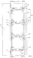
- FIG. 1 and 2 show a duct installation box 130 which can be installed in the electrical duct and a combination of duct and electrical socket composed of three duct installation boxes installed in the electrical duct.
- the headers 110 and the edges 132, parallel to the electrical duct, of the duct installation boxes 130 together form the cover 108 for the duct / electrical box combination composed of duct installation boxes and described in this example.
- Various installation devices and devices such as sockets, switches, terminals for tele, telephone and data transmission connections and other similar electrical equipment, can be installed in the duct installation box 130.
- the duct installation box 130 consists of a border 132, fastening members 134 and 136 for the head strip, fastening members 138 and 140, with which adjacent protective sockets are fastened to one another, fastening member 142 and contact surface 144, via which the protective sockets are fastened in the electrical duct, holding member 48 with the movement of the duct installation box in the direction of the electrical duct is prevented, and predetermined breaking points 146 for the introduction of the electrical cables required for installation devices or devices to be installed in the duct construction box.
- the duct installation boxes 130 have fastening members 138 and 140 known per se for fastening duct installation boxes to one another.
- the duct installation box 130 also includes fastening members 142 known as such for fastening them in the electrical duct 10.
- the contact surface 144 prevents the Duct installation box immersed too deep in the electrical duct.
- Holding grooves 14 can be machined on the inwardly curved edges of the electrical channel 10.
- a holding part 48 can accordingly be arranged, which engages in one of the above-mentioned holding grooves 14 and thereby prevents the respective duct electrical socket and the other duct electrical sockets coupled therewith moving in the electrical duct in its longitudinal extent.
- the central plate (not shown) assigned to each installation device is attached to the duct installation box as the top one, which completes the installation in this regard.
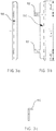
- the head strip 110 shown in FIG. 3, forms the head part of the cover 108 of the duct / electrical socket combination.
- the headers 110 can be fastened without tools, with suitable, preferably male fastening members 112 known as such, and easily detached, for example by hand.
- suitable, preferably male fastening members 112 known as such
- the distance A of the fastening member 136 from the edge of the duct installation box should be the same as the distance A 'of the fastening member 134 from Edge of the duct installation box.
- the distance B of the fastening element 136 from the edge of the duct installation box should correspond to the distance B 'of the fastening element 134 from the edge of the duct installation box.
- the headers are thus designed in such a way that loose parts of a single type, ie headers 110, are required to form the cover 108 for the duct / electrical socket combination, which the electrician can easily carry, for example in the breast pocket.
- the electrical duct 10 shown in FIG. 4, which can be installed on the wall, is mounted horizontally, preferably directly below the window plane, or vertically as required.
- a duct-electrical socket combination is installed, which is composed of duct electrical sockets, in this case two double protective contact safety socket outlets 80 and a connecting part 20 (not visible, shown in FIG. 5a).
- the parts of the duct / socket combination installed in the electrical duct 10, i.e. the connection part 20 and the duct sockets 80, are e.g. mechanically coupled with one another in the known ways mentioned in patent application FI.
- the headers 110 are attached to the head sides of the duct sockets 80.
- An angle plug 98 is coupled to the one channel socket 80.
- a duct-electrical socket combination according to FIG. 4 is installed in an electrical duct 10, without front plates 12 of the electrical duct and head strips 110.
- This channel-electrical socket combination includes two channel sockets 80 and a connecting part 20.
- One of the inwardly bent edges of the electrical channel has holding grooves 14 in the part that lies below the front plate.
- sem can in turn arrange a holding member 48 which engages in one of the above-mentioned holding grooves 14 and thereby prevents the part of the duct / electrical outlet combination in question and the rest associated therewith Move parts of the duct / electrical socket combination in the longitudinal direction of the electrical duct.
- FIG. 5b shows a duct socket installed in the electrical duct 10 seen from the top of the electrical duct.
- the edges 82 of the device panel 82 relative to the rest of the surface is clearly recognizable.
- the edges 86 of the device panel 82 resting on the electrical channel 10 are at different heights relative to the rest of the surface of the device panel 82 and thus form part of the lateral edge of the cover of the channel / electrical socket combination.
- the device cover is an integral part of the channel socket 80.
- This figure also shows the position of the retaining grooves 14 in the one below the front panel 12, inwardly bent edge of the electrical channel 10.
- the fastening members 90 and 50 can be the end the cover the headers 110 forming the duct / socket combination.
- the duct / socket combination which can be installed in the electrical duct can be formed from a separate connection part 20 + at least one duct electrical socket 80 or a connection part 28 which belongs to a duct electrical socket and the duct electrical sockets 80 which may be coupled therewith.
- the fastening elements 90 similar fastening elements and at the other end fastening elements 50 similar fastening elements.
- duct electrical outlet is understood to mean numerous alternative electrical accessories that can be installed in an electronics room, such as duct sockets, various installation devices and devices without a separate protective box, various installation devices and devices used in duct installation sockets, such as sockets, switches, connection terminals for tele, telephone and data transmission connections and other electrical accessories of this type.
- the duct-electrical socket combination consisting solely of the connection part 20 + duct sockets 80, is installed in the electrical duct 10, the lateral edges of the part of the duct socket protruding from the electrical duct, the device cover 82, form part of the Flank of cover 108 of the channel-electrical socket combination.
- the headers are on the head sides of the duct-electrical combination, at one end on the fastening members 90 of the duct socket and the other end on the fastening members 50 of the connector 110 attached, which thus complete the flanks of the cover formed by the edges of the channel sockets to a complete and aesthetic whole. So that the head strip 110 shown in FIG.
- the distances A, B and C connected to the fastening elements 90 of the head strip 110 are the same as in the case of head strip 110 and the distances A ', B connected to the fixing elements 50 also in this duct / electrical socket combination 'and C' the same as for header 110.
- a cover can generally be formed for duct / socket combination installed in the electrical duct according to the examples. If a duct electrical socket is installed in the electrical duct, the lateral edges of the part of the duct electrical socket protruding from the electrical duct, that is to say the edge region 86 of the device cover 82 parallel to the electrical duct in the case of a duct socket and the edge 132 parallel to the electrical duct form the duct -Installation box 130 or the band parallel to the electrical duct of an installation device / device or protective box installed in the duct socket or its share of the flank of the cover in those cases where installation boxes installed in the electrical duct are used as part of a duct electrical socket.
- the headers are attached to the top of the duct-electrical outlet combination, either on the duct electrical outlet or the connecting part, or the headers are installed as separate parts, thus forming the edges formed by the edges of the duct-electrical outlets Complete the flanks of the cover to create a complete and aesthetic whole.
- the end face of the cover can be formed from different head strips, which are located on the end faces of the duct electrical installation group. Some alternative header bars are shown below.
- a head strip has, for example, suitable fastening elements for fastening the same to the end face of the front plate 12, with the front plates 12 being attached last to the installed end of the duct / electrical socket combination in the electrical duct 10, on the end faces of which are connected to the duct / electrical socket combination. It is by the of the Flanks of the cover, that is, a cover formed from the edges of the duct electrical outlets and to the front plates 12 attached skirt strips formed a complete whole.
- the headrail optionally has, for example, suitable fastening members for fastening the same to the electrical duct, the headrail being fastened to the electrical duct 10 in the electrical duct 10 when the duct-electrical socket combination is installed.
- suitable fastening members for fastening the same to the electrical duct, the headrail being fastened to the electrical duct 10 in the electrical duct 10 when the duct-electrical socket combination is installed.
- a complete whole is formed by the cover formed by the flanks of the cover plate, that is, by the edges of the duct electrical outlets and in the electrical duct 10 headers, after which the front plates 12 can be attached.
- the headers can be attached without tools using known, preferably male fastening members.
- duct electrical outlets 80, 130 and the possible connection part 20 are installed in such a way that they are held close together in the electrical duct, so that there are no unsightly gaps in the cover.
- the duct electrical sockets for example, have suitable organs for mechanically coupling them to one another, with no disruptive gaps being created between the duct electrical sockets.
- a holding member 48 is accordingly arranged, which engages in one of the holding grooves mentioned and thus prevents the concerned with the duct-electrical socket or the connector and the other coupled duct-electrical sockets in the electrical duct, in its longitudinal extent .
- the duct electrical sockets of a duct electrical socket combination do not necessarily have to be mechanically coupled to one another. It is enough that they are held together in one way or another without gaps.
- the headers to be attached to the duct-electrical socket combination are identical in shape. Only the different color alternatives used for the electrical outlets result in differences in the appearance of the headers.
- the cover, formed on the one hand by separate headers and on the other hand by the flanks of the duct electrical outlets, can be installed effortlessly and cleanly, requires few parts and offers a very cost-effective way of forming different cover alternatives.
- duct sockets or duct installation sockets are used as duct electrical sockets
- electrical socket numerous alternative electrical devices that can be installed in the electrical duct or on the wall, such as duct sockets, various installation devices and devices arranged in duct electrical sockets or wall sockets, such as sockets, connecting terminals for telephones, telephones and Data transmission connections and other electrical accessories of this type.
- the electrical equipment installed in the electrical duct is summarized under the name duct electrical outlets, as was mentioned earlier.
- the invention described above is a solution to installation problems with regard to the current electrical ducts.
- the invention also provides completely new, versatile alternatives for installing covers for various duct-outlet combinations located in walls or electrical ducts, so that the end result is inexpensive and aesthetically useful in terms of manufacturing and installation costs.
Landscapes
- Engineering & Computer Science (AREA)
- Architecture (AREA)
- Civil Engineering (AREA)
- Structural Engineering (AREA)
- Details Of Indoor Wiring (AREA)
- Connection Or Junction Boxes (AREA)
- Casings For Electric Apparatus (AREA)
- Connector Housings Or Holding Contact Members (AREA)
- Closures For Containers (AREA)
- Insulating Bodies (AREA)
- Brushes (AREA)
- Connecting Device With Holders (AREA)
- Connections Arranged To Contact A Plurality Of Conductors (AREA)
- Pharmaceuticals Containing Other Organic And Inorganic Compounds (AREA)
- Pyrane Compounds (AREA)
- Patch Boards (AREA)
Applications Claiming Priority (2)
| Application Number | Priority Date | Filing Date | Title |
|---|---|---|---|
| FI910559A FI86928C (fi) | 1991-02-05 | 1991-02-05 | Taeckplatta foer en kombination av eldosor |
| FI910559 | 1991-02-05 |
Publications (2)
| Publication Number | Publication Date |
|---|---|
| EP0498402A1 true EP0498402A1 (fr) | 1992-08-12 |
| EP0498402B1 EP0498402B1 (fr) | 1996-01-03 |
Family
ID=8531862
Family Applications (1)
| Application Number | Title | Priority Date | Filing Date |
|---|---|---|---|
| EP92101919A Expired - Lifetime EP0498402B1 (fr) | 1991-02-05 | 1992-02-05 | Couverture pour une prise électrique ou une combinaison de prises électriques |
Country Status (6)
| Country | Link |
|---|---|
| EP (1) | EP0498402B1 (fr) |
| AT (1) | ATE132662T1 (fr) |
| DE (1) | DE59204870D1 (fr) |
| DK (1) | DK0498402T3 (fr) |
| FI (1) | FI86928C (fr) |
| NO (1) | NO303157B1 (fr) |
Cited By (4)
| Publication number | Priority date | Publication date | Assignee | Title |
|---|---|---|---|---|
| FR2704990A1 (fr) * | 1993-05-07 | 1994-11-10 | Alusor | Dispositif de colonne de distribution pour conduits ou câbles. |
| FR2708386A1 (fr) * | 1993-07-27 | 1995-02-03 | Nozick Jacques | Boîtier de connecteurs électriques prééquipé. |
| FR2776134A1 (fr) * | 1998-03-13 | 1999-09-17 | Legrand Sa | Support d'appareillage a rapporter sur le socle d'une goulotte a retours diriges l'un vers l'autre |
| AU773746B2 (en) * | 1999-10-15 | 2004-06-03 | Legrand France | Support for devices, in particular for electrical devices, to be attached to the base section of trunking |
Citations (2)
| Publication number | Priority date | Publication date | Assignee | Title |
|---|---|---|---|---|
| DE3610117A1 (de) * | 1986-03-26 | 1987-10-01 | Niedax Gmbh | Abdeckung der einbauoeffnung von geraeteeinbaukanaelen oder geraetekaesten |
| DE3643559A1 (de) * | 1986-12-19 | 1988-06-30 | Bettermann Obo Ohg | In einem bruestungskanal befestigbare einbaudose |
-
1991
- 1991-02-05 FI FI910559A patent/FI86928C/fi active
-
1992
- 1992-02-04 NO NO19920456A patent/NO303157B1/no not_active IP Right Cessation
- 1992-02-05 EP EP92101919A patent/EP0498402B1/fr not_active Expired - Lifetime
- 1992-02-05 DK DK92101919.6T patent/DK0498402T3/da active
- 1992-02-05 DE DE59204870T patent/DE59204870D1/de not_active Expired - Lifetime
- 1992-02-05 AT AT92101919T patent/ATE132662T1/de active
Patent Citations (2)
| Publication number | Priority date | Publication date | Assignee | Title |
|---|---|---|---|---|
| DE3610117A1 (de) * | 1986-03-26 | 1987-10-01 | Niedax Gmbh | Abdeckung der einbauoeffnung von geraeteeinbaukanaelen oder geraetekaesten |
| DE3643559A1 (de) * | 1986-12-19 | 1988-06-30 | Bettermann Obo Ohg | In einem bruestungskanal befestigbare einbaudose |
Cited By (4)
| Publication number | Priority date | Publication date | Assignee | Title |
|---|---|---|---|---|
| FR2704990A1 (fr) * | 1993-05-07 | 1994-11-10 | Alusor | Dispositif de colonne de distribution pour conduits ou câbles. |
| FR2708386A1 (fr) * | 1993-07-27 | 1995-02-03 | Nozick Jacques | Boîtier de connecteurs électriques prééquipé. |
| FR2776134A1 (fr) * | 1998-03-13 | 1999-09-17 | Legrand Sa | Support d'appareillage a rapporter sur le socle d'une goulotte a retours diriges l'un vers l'autre |
| AU773746B2 (en) * | 1999-10-15 | 2004-06-03 | Legrand France | Support for devices, in particular for electrical devices, to be attached to the base section of trunking |
Also Published As
| Publication number | Publication date |
|---|---|
| FI910559A7 (fi) | 1992-07-15 |
| NO920456L (no) | 1992-08-06 |
| NO920456D0 (no) | 1992-02-04 |
| NO303157B1 (no) | 1998-06-02 |
| DE59204870D1 (de) | 1996-02-15 |
| EP0498402B1 (fr) | 1996-01-03 |
| FI910559A0 (fi) | 1991-02-05 |
| ATE132662T1 (de) | 1996-01-15 |
| FI86928B (fi) | 1992-07-15 |
| FI86928C (fi) | 1992-10-26 |
| DK0498402T3 (da) | 1996-02-05 |
Similar Documents
| Publication | Publication Date | Title |
|---|---|---|
| DE3807645C2 (de) | Steckverbindungssystem für elektrische Leiter | |
| DE2642066C2 (fr) | ||
| EP2559107B1 (fr) | Borne de connexion de conducteur principal | |
| DE4036249A1 (de) | Aus einem metallischen werkstoff, wie stahlblech, bestehender kanal zur unterbringung von elektrischen installationseinrichtungen | |
| DE2711324C2 (de) | Gehäusebausatz für elektrische Installationsgeräte, insbesondere von Sprech- und/oder Klingelanlagen | |
| EP0466043B1 (fr) | Installation de distribution comprenant au moins deux rangées d'appareils électriques de type étroit | |
| EP0733276B1 (fr) | Boite de connexion d'appareils pour montage affleure dans des conduits d'installation | |
| EP0498402B1 (fr) | Couverture pour une prise électrique ou une combinaison de prises électriques | |
| DE3606622A1 (de) | Modularer mehrzweck-buchsenverbinderblock | |
| DE3842205C2 (de) | Gehäuse für den Anschluß von Kommunikationssystemen | |
| DE4004340C2 (fr) | ||
| DE634911C (de) | Gehaeuse fuer die Aufputzbefestigung von elektrischen Installationsapparaten, wie Schaltern, Steckvorrichtungen u. dgl. | |
| DE69412097T2 (de) | Modulares System für Deckelrahmen | |
| DE4230236A1 (de) | Bausatz für Kabelendverschlüsse oder Gehäuse für die elektrische Nachrichtentechnik | |
| DE2201883A1 (de) | Kontaktbuchse fuer elektrische installationsgeraete | |
| DE3434643C2 (fr) | ||
| DE4112651A1 (de) | Anreihbarer klemmenblock | |
| DE1024138B (de) | Wandkasten- bzw. -dosengehaeuse, insbesondere fuer Unterputzanordnung | |
| EP0762587A1 (fr) | Couvercle pour dispositif d'installation électrique | |
| DE69406024T2 (de) | Vorverdrahtete Anschlussklemmleiste | |
| DE10155924A1 (de) | Vorrichtung zum Verbinden für zwei elektrische Kabel | |
| DE29512560U1 (de) | Gehäuseanordnung für elektrische Elemente | |
| DE2811342A1 (de) | Installationskleinverteiler-system | |
| DE9106787U1 (de) | Elektrodose | |
| DE1590331A1 (de) | Kabelfuehrungskanal |
Legal Events
| Date | Code | Title | Description |
|---|---|---|---|
| PUAI | Public reference made under article 153(3) epc to a published international application that has entered the european phase |
Free format text: ORIGINAL CODE: 0009012 |
|
| AK | Designated contracting states |
Kind code of ref document: A1 Designated state(s): AT BE DE DK NL SE |
|
| 17P | Request for examination filed |
Effective date: 19921210 |
|
| 17Q | First examination report despatched |
Effective date: 19940407 |
|
| GRAA | (expected) grant |
Free format text: ORIGINAL CODE: 0009210 |
|
| AK | Designated contracting states |
Kind code of ref document: B1 Designated state(s): AT BE DE DK NL SE |
|
| REF | Corresponds to: |
Ref document number: 132662 Country of ref document: AT Date of ref document: 19960115 Kind code of ref document: T |
|
| REG | Reference to a national code |
Ref country code: DK Ref legal event code: T3 |
|
| REF | Corresponds to: |
Ref document number: 59204870 Country of ref document: DE Date of ref document: 19960215 |
|
| PLBE | No opposition filed within time limit |
Free format text: ORIGINAL CODE: 0009261 |
|
| STAA | Information on the status of an ep patent application or granted ep patent |
Free format text: STATUS: NO OPPOSITION FILED WITHIN TIME LIMIT |
|
| 26N | No opposition filed | ||
| NLS | Nl: assignments of ep-patents |
Owner name: LEXEL ELECTRIC OY Effective date: 20060503 |
|
| PGFP | Annual fee paid to national office [announced via postgrant information from national office to epo] |
Ref country code: DK Payment date: 20110210 Year of fee payment: 20 |
|
| PGFP | Annual fee paid to national office [announced via postgrant information from national office to epo] |
Ref country code: DE Payment date: 20110218 Year of fee payment: 20 Ref country code: NL Payment date: 20110216 Year of fee payment: 20 Ref country code: SE Payment date: 20110214 Year of fee payment: 20 Ref country code: AT Payment date: 20110214 Year of fee payment: 20 |
|
| PGFP | Annual fee paid to national office [announced via postgrant information from national office to epo] |
Ref country code: BE Payment date: 20110211 Year of fee payment: 20 |
|
| REG | Reference to a national code |
Ref country code: DE Ref legal event code: R071 Ref document number: 59204870 Country of ref document: DE |
|
| REG | Reference to a national code |
Ref country code: DE Ref legal event code: R071 Ref document number: 59204870 Country of ref document: DE |
|
| REG | Reference to a national code |
Ref country code: NL Ref legal event code: V4 Effective date: 20120205 |
|
| REG | Reference to a national code |
Ref country code: DK Ref legal event code: EUP |
|
| BE20 | Be: patent expired |
Owner name: *LEXEL ELECTRIC OY Effective date: 20120205 |
|
| REG | Reference to a national code |
Ref country code: SE Ref legal event code: EUG |
|
| PG25 | Lapsed in a contracting state [announced via postgrant information from national office to epo] |
Ref country code: DE Free format text: LAPSE BECAUSE OF EXPIRATION OF PROTECTION Effective date: 20120206 |
|
| REG | Reference to a national code |
Ref country code: AT Ref legal event code: MK07 Ref document number: 132662 Country of ref document: AT Kind code of ref document: T Effective date: 20120205 |