EP0498570B1 - Mesure quantitative du flux sanguin utilisant le codage de la vitesse par fourier cylindrique localisé - Google Patents
Mesure quantitative du flux sanguin utilisant le codage de la vitesse par fourier cylindrique localisé Download PDFInfo
- Publication number
- EP0498570B1 EP0498570B1 EP92300819A EP92300819A EP0498570B1 EP 0498570 B1 EP0498570 B1 EP 0498570B1 EP 92300819 A EP92300819 A EP 92300819A EP 92300819 A EP92300819 A EP 92300819A EP 0498570 B1 EP0498570 B1 EP 0498570B1
- Authority
- EP
- European Patent Office
- Prior art keywords
- subject
- flow
- pulse
- gradient
- fluid flow
- Prior art date
- Legal status (The legal status is an assumption and is not a legal conclusion. Google has not performed a legal analysis and makes no representation as to the accuracy of the status listed.)
- Expired - Lifetime
Links
Images







Classifications
-
- A—HUMAN NECESSITIES
- A61—MEDICAL OR VETERINARY SCIENCE; HYGIENE
- A61B—DIAGNOSIS; SURGERY; IDENTIFICATION
- A61B5/00—Measuring for diagnostic purposes; Identification of persons
- A61B5/72—Signal processing specially adapted for physiological signals or for diagnostic purposes
- A61B5/7235—Details of waveform analysis
- A61B5/7253—Details of waveform analysis characterised by using transforms
- A61B5/7257—Details of waveform analysis characterised by using transforms using Fourier transforms
-
- A—HUMAN NECESSITIES
- A61—MEDICAL OR VETERINARY SCIENCE; HYGIENE
- A61B—DIAGNOSIS; SURGERY; IDENTIFICATION
- A61B5/00—Measuring for diagnostic purposes; Identification of persons
- A61B5/02—Detecting, measuring or recording for evaluating the cardiovascular system, e.g. pulse, heart rate, blood pressure or blood flow
- A61B5/026—Measuring blood flow
- A61B5/0263—Measuring blood flow using NMR
-
- G—PHYSICS
- G01—MEASURING; TESTING
- G01R—MEASURING ELECTRIC VARIABLES; MEASURING MAGNETIC VARIABLES
- G01R33/00—Arrangements or instruments for measuring magnetic variables
- G01R33/20—Arrangements or instruments for measuring magnetic variables involving magnetic resonance
- G01R33/44—Arrangements or instruments for measuring magnetic variables involving magnetic resonance using nuclear magnetic resonance [NMR]
- G01R33/48—NMR imaging systems
- G01R33/54—Signal processing systems, e.g. using pulse sequences ; Generation or control of pulse sequences; Operator console
- G01R33/56—Image enhancement or correction, e.g. subtraction or averaging techniques, e.g. improvement of signal-to-noise ratio and resolution
- G01R33/563—Image enhancement or correction, e.g. subtraction or averaging techniques, e.g. improvement of signal-to-noise ratio and resolution of moving material, e.g. flow contrast angiography
-
- A—HUMAN NECESSITIES
- A61—MEDICAL OR VETERINARY SCIENCE; HYGIENE
- A61B—DIAGNOSIS; SURGERY; IDENTIFICATION
- A61B5/00—Measuring for diagnostic purposes; Identification of persons
- A61B5/72—Signal processing specially adapted for physiological signals or for diagnostic purposes
- A61B5/7271—Specific aspects of physiological measurement analysis
- A61B5/7285—Specific aspects of physiological measurement analysis for synchronizing or triggering a physiological measurement or image acquisition with a physiological event or waveform, e.g. an ECG signal
-
- G—PHYSICS
- G01—MEASURING; TESTING
- G01R—MEASURING ELECTRIC VARIABLES; MEASURING MAGNETIC VARIABLES
- G01R33/00—Arrangements or instruments for measuring magnetic variables
- G01R33/20—Arrangements or instruments for measuring magnetic variables involving magnetic resonance
- G01R33/44—Arrangements or instruments for measuring magnetic variables involving magnetic resonance using nuclear magnetic resonance [NMR]
- G01R33/446—Multifrequency selective RF pulses, e.g. multinuclear acquisition mode
Definitions
- This invention relates to quantitative measurement of blood flow, and more specifically, quantitative measurement of blood flow using Magnetic Resonance Imaging.
- Angiography or the imaging of vascular systems by Magnetic Resonance (MR) has been demonstrated using a variety of techniques based on time-of-flight phenomena and the phenomena of velocity-induced phase shifts.
- MR Magnetic Resonance
- volume pixel may contain a distribution of velocities which interfere with one another in the detection or data collection process.
- fluid flow measurements are a good indication of hemodynamic properties of a given vessel. These hemodynamic properties are important in Medical Applications such as in diagnosing a variety of abnormalities and diseases. It would be useful to be able to acquire the hemodynamic properties without the use of invasive techniques.
- the present invention provides a more selective method of measuring fluid flow through use of MR imaging than heretofore attainable.
- the method provides for quantitative measurement of fluid flow by applying a homogeneous magnetic field over the subject to be imaged and performing a plurality of magnetic resonance scans, followed by reconstruction of the data to calculate the flow velocities of the fluid.
- the scan is executed by first applying a cylindrical NMR excitation to the portion of the subject which is to be imaged.
- a flow encoding magnetic field gradient is applied along the direction in which flow is to be measured.
- data are collected by use of an antenna sensing the NMR signal which is re-radiated from the subject and stored for future reconstruction.
- Cylindrical NMR excitation of the subject is accomplished by simultaneous application of two mutually orthogonal time-changing magnetic field gradients accompanied by an rf pulse of a predetermined amplitude and duration.
- flow encoding can take place.
- the scan is repeated many times, with the flow encoding magnetic gradient having a constant predetermined amplitude for each scan, but differing in amplitude for successive scans.
- the flow encoding magnetic gradient pulse will have two lobes, each lobe having the same area under an amplitude versus duration curve, but having opposite polarities.
- a bipolar magnetic readout gradient is applied parallel to the axis of the excitation cylinder.
- An antenna senses the amount of rf signal re-radiated by the excitation cylinder. These rf signal data are stored, and the entire scan is repeated for another amplitude value of the flow-encoded magnetic gradient. Once all the data are acquired, a two dimensional Fourier transform of the scan data is performed to reconstruct the fluid velocity profile.
- the fluid velocity profile combined with the cross sectional diameter of a vessel to be imaged, can be used to calculate the fluid flow through the vessel.
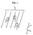
- spins Free unpaired spinning protons in the nucleus of a molecule, normally hydrogen nuclei 10, 11 and 12 as shown in Fig. 1, align themselves in a magnetic field B0 such that their axes precess about the magnetic field.
- Spins 10, 11 and 12 represent a sample of the population of spins in a given sample. Since there is a population of spins, the macroscopic total of aligned spins cause a net longitudinal magnetization 31 along the magnetic field B0. The net sum of the total population 10, 11 and 12 also results in a small transverse magnetization (“M xy ”) 32.
- M xy small transverse magnetization
- the net transverse magnetization 32 can be increased by forcing spins 10, 11 and 12 out of alignment with magnetic field B0 by a force applied by a tuned radio frequency (rf) pulse, or by an external magnetic field.
- rf radio frequency
- an rf pulse applied in the presence of a magnetic field of predefined strength causes excitation or resonance of the spins, increasing transverse magnetization of the spins as represented by spins 14, 15, and 16 of Fig. 2.
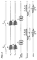
- the rf pulse 62 changes amplitude over time as the G x and G y orthogonal magnetic field gradients 63 and 64 create a resultant gradient field vector G r as shown in Fig. 4.
- the tip of vector G r traces a spiral.
- the prior art employs slab or slice excitation geometry for MR imaging.
- FIG. 3 is chosen to be the weighted two-dimensional Fourier transform of the desired excitation profile as disclosed by Pauly J, Nishimura D, Macovski A. "A K-Space Analysis of Small Tip-Angle Excitation” in J. Magn. Reson. 81:43, (1989).
- the spiral 91 of Fig. 4 can be traversed at a nonuniform rate to minimize pulse duration and double the bandwidth relative to a traversal at constant angular rate, under conditions of constrained gradient slew rate, consistent with the teachings of Hardy C.J., Cline H.E. "Broadband Nuclear Magnetic Resonance Pulses with Two-Dimensional Spatial Selectivity” in J. Appl. Phys. 66:1513, (1989).
- the rf waveform 62 is weighted by a factor which corrects for the nonuniform coverage of k-space by the spiral near the origin 92.
- a fuller discussion is given in Hardy C.J., Cline H.E., Bottomley P.A. "Correcting for Nonuniform K-Space Sampling in Two-Dimensional NMR Selective Excitation” in J. Magn. Reson. 87:639, (1990) hereby incorporated by reference and made part of this disclosure. This weighting removes baseline artifacts which can add contaminating signals from outside the central selected region to the excitation.
- Spiral-trajectory excitation pulses produce aliasing ring artifacts at radii determined by the length of the spiral 91 and the number of cycles in the spiral, as described by Hardy C.J., Cline HE. "Spatial Localization in Two Dimensions Using NMR Designer Pulses” in J. Magn. Reson. 82: 647, (1989) hereby incorporated by reference and made part of this disclosure.
- the rf pulse 62 of Fig. 3 was chosen to maximize the ratio between aliasing-ring radius (not shown) and excitation cylinder radius 85, shown in Fig. 5, without producing distortion of the profile or aliasing rings at the perimeter of the cylinder 81 (shown in Fig. 4), while exciting a Gaussian profile.
- excitation cylinder 81 After application of the rf pulse 62 and magnetic gradients 63 and 64, shown in Fig. 3, excitation cylinder 81 has a transverse magnetization as indicated in Figs. 6a and 6b.
- the center of cylinder 81 is at displacement x c .
- the transverse magnetization M xy At displacement x1, shown in Fig. 6a, the transverse magnetization M xy is represented as x1, as shown in Fig. 6b.
- the magnetization M xy remains substantially constant across the diameter of cylinder 81, having a magnetization amplitude m which drops off at radius x2 of Fig. 6a, corresponding to point x2 on the graph of Fig. 6b.
- the present invention utilizes Fourier velocity encoding with a pulse sequence 61 shown in Fig. 3
- Fig. 7 is an amplitude vs. time diagram of a single component of the transverse magnetization vector 32 of Fig. 2 as it rotates at a given location in the sample.
- the vector rotates at a specific constant frequency during period 54.
- Magnetic field gradient pulse 57 is applied during period 55, increasing the frequency or rate of change in phase of transverse magnetization 32 depending upon the area of gradient pulse 57.
- the transverse magnetization reverts back to its original frequency, but the phase is increased, in this case, by 90 degrees. This is called phase evolution. It must be noted that if the polarity of gradient pulse 57 is reversed, it would cause a reverse effect on the phase shift, retarding the phase by 90 degrees.
- each spin 14, 15, 16 of Figs. 2 is directly related to the position of the spin along the magnetic field gradient, the amplitude of the gradient applied to it, and the time during which it is applied (or the area under the gradient lobe 57).
- the phase shift of stationary spin is directly proportional to the lobe area 57.
- Fig. 8 shows a spin 17 located at point 26 moving at a velocity 41 towards point 27.
- a negative gradient 22 is applied.
- spin 17 is at point 26a a positive gradient 23 is applied.
- the phase shift induced by gradient 23 is substantially opposite to that induced by gradient 22 because the gradient amplitude polarities 24 and 25 are substantially opposite, but are not exactly opposite due to the physical displacement of spin 17.
- the resultant phase shift arising from the application of the bipolar gradient comprised of gradients 22 and 23 is directly proportional to the velocity of spin 17.
- a spin moving in the opposite direction between points 27 and 26 will experience phase evolution which is exactly opposite that of spin 17.
- a spin which is not moving in a direction along the gradient 22 or 23, such as spin 18, will first experience an negative gradient amplitude 28 followed by a positive gradient amplitude 29 of equal magnitude, the positive and negative amplitudes thereby cancelling each other out.
- Fig. 8 thus illustrates that the velocity of the spin 17 moving along a bipolar gradient 22 and 23 can be encoded by its phase evolution.
- Fig. 8 also shows that a spin 18 which does not have a velocity along the gradient will experience no additional phase evolution due to the bipolar magnetic field gradient.
- ⁇ is the gyromagnetic ratio specific to a given element
- V is the component 42 of the spin's velocity 41 parallel to the direction of the gradient pulse, as shown in Fig. 8.
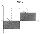
- T is shown in Fig. 9 as the time between the centers of the lobes of the magnetic gradient pulse applied along the line in which flow is to be measured
- a g is the area 51, 52 (gradient strength x duration of application) of one lobe of the bipolar pulse. Equation [1] ignores phase shifts which can arise from higher orders of motion such as acceleration and jerk.
- the present invention in order to encode fluid flow, as represented by a vector 83, the present invention employs a flow encoding magnetic field gradient applied along a direction in which flow is intended to be measured, and represented by a vector 86.
- This causes phase evolution of the spins to occur, with the higher velocity spins evolving faster than the lower velocity spins.
- the velocity 42 of a sample of spins 17 and 18, as represented in Fig. 8 can be quantitatively measured if the phase shift can be determined.
- MR signals from a spatial region come from an ensemble of spins and if these spins are moving, their velocity is characterized by a distribution, rather than a single velocity. This distribution can be broad enough to cause the phase of the component spin signals to cancel and thus result in a loss of signal.
- One way to overcome the problem of spin velocities interfering with each other upon data acquisition is to convert one spatial dimension of a conventional image into a velocity dimension. This adds a dimension in which the velocity data (and its distribution) can be measured.
- the present invention exploits the properties of the Fourier Transform to separate the constituent velocities on reconstruction and prevent signal loss. This is done by, for example, on a series of excitations applying successively a larger flow encoding gradients 51, 52, of Fig. 9, 61, 71 of Fig.3 or larger separations T, as shown in Fig. 9, and sampling the re-radiated data. This allows data to be collected for a number of flow encoding gradient amplitudes. Fourier transformation is then used to separate the various velocity constituents by virtue of their modulation frequencies to produce a data vector which presents signal intensity as a function of velocity. It will be noted that the bipolar flow-encoded gradient wave forms 61, 71 of Fig. 3 are two of a series of wave forms each having a differing amplitude.
- the present invention bears some similarity to the Fourier-encoded velocity measurements proposed by Feinberg et al.and Hennig et al., supra; however the pulse sequences utilized by the present invention differ from the pulse sequences of Feinberg et al. and Hennig et al. Cylindrical field excitation and independent flow encoding geometry are not employed by Feinberg et al. and Hennig et al.
- Data are acquired by applying a readout magnetic field gradient 65, 75, as shown in Fig. 3 and represented by vector 82 of Fig. 5, parallel to the axis 122 of the excitation cylinder 81 of Fig. 5.
- the spins 17, 18 represented in Fig. 8 re-radiate photons when in the excited state and placed in a magnetic field gradient such as the readout gradient 65, 75, as represented by vector 82 of Fig. 5.
- Each readout gradient pulse 65, 75 has two lobes as shown in Fig. 3.
- the first lobe has an area 66, 76 equal to the first half 67,77 of the second lobe.
- the readout gradient causes a negative phase evolution during application of the first lobe 66, 76, followed by a positive phase evolution during application of the first half 67, 77 of the second lobe, causing a rephasing at its midpoint 69, 79.
- the peak of the signal echo 101, 111 occurs at this point in time. This echo is a gradient recalled echo. Signals 101, 111, etc. are sensed and stored.
- the resulting data set has a single spatial dimension (i.e. the readout dimension) and one velocity dimension which is sensitive only to the component of velocity which is parallel to the applied flow encoding magnetic field gradient pulse 42, shown in Fig. 8.
- the relative orientations of the flow encoding gradient 85, readout gradient 82 and excitation cylinder 81 are not constrained, and can be orthogonal, parallel or oblique.
- the cylinder 81 can be reoriented by mixing the gradient G x waveforms 63, 73 and G y waveforms 64, 74 from Fig. 3 and offset from gradient isocenter by frequency modulating of the rf pulse 62 of Fig. 3.
- the velocity resolution of the resulting flow measurement can be calculated by using the Nyquist criterion with equation [1].
- V res 1 2 ⁇ TA g(max)
- the pulse sequence illustrated in Fig. 3 is very flexible and can be applied in a variety of manners. Since the orientation of the readout gradient 82, flow encoding gradient 86 and excitation cylinder 81, as shown in Fig. 5, are independent of one another, it is possible to optimize the pulse sequence for different vascular anatomies and applications. For example, the geometry shown in Fig. 5 can be modified such that the flow-encoding gradients are applied in three orthogonal directions in three successive scans. (See U.S. Patent 4,796,635, Dumoulin, issued Jan. 10, 1989.) This triples the required scan time, but permits the quantification of blood flow without prior knowledge of the vessel geometry.
- Synchronization of acquisition with the cardiac cycle is essential if the temporal characteristics of blood flow are to be measured. velocity measurements performed with cardiac gating are made synchronously over a large number of cardiac cycles and permit the differentiation of constant and periodic flow. Under these conditions, both periodic and constant flow behavior are easily measured and the velocity distribution is well characterized (i.e. there is little signal intensity at unexpected velocities).
- Another variation of the sequence that may be employed in the present invention is the conversion of the bipolar flow-encoding pulse into a three-lobed acceleration encoding pulse as shown in Fig. 10 or a three-lobed acceleration compensated/velocity encoding pulse.
- a three-lobed acceleration compensated/velocity encoding pulse See Dumoulin C.L., Souza S.P., Walker M.F. and Yoshitome E. "Time-resolved Magnetic Resonance Angiography", Mag. Reson. Med . 6:275, (1988) hereby incorporated by reference and made part of this disclosure.
- the application of Fourier acceleration encoding to in-vivo systems is limited by the strength of the gradient subsystem in currently available instruments, with maximum gradient amplitudes on the order of 1 G/cm.
- Use of a three-lobed acceleration pulse would result in suppression of any differential orders of motion below the second differential order of motion, which is useful in imaging acceleration of fluids. In other words, non-
- Fig. 11 is a simplified block diagram of the major components of an NMR imaging system suitable for use with the NMR pulse sequences of the invention described herein.
- the system generally designated 400, is made up of a general purpose mini-computer 401 which is functionally coupled to disk storage unit 403 and an interface unit 405.
- An RF transmitter 402, signal averager 404, and gradient power supplies 406, 408 and 410 for energizing, respectively, x, y, z gradient coils 416, 418, and 420 are coupled to computer 401 through interface unit 405.
- RF transmitter 402 is gated with pulse envelopes from computer 401 to generate RF pulses having the required modulation to excite nuclear resonance in the subject under study.
- the RF pulses are amplified in RF power amplifier 412 to levels varying from 100 watts to several kilowatts, depending on the imaging method, and applied to transmitter coil 424. The higher power levels are necessary for large sample volumes such as in whole body imaging, and where short duration pulses are required to excite large NMR frequency bandwidths.
- the NMR signal is sensed by receiver coil 426, amplified in a low noise preamplifier 422, and applied for further amplification, detection, and filtering to receiver 414.
- the signal is then digitized for averaging by signal averager 404 and for precessing by computer 401.
- Preamplifier 422 and receiver 414 are protected from the RF pulses during transmission by active gating or by passive filtering.
- Computer 401 provides gating and envelope modulation for the NMR pulses, blanking for the preamplifier and RF power amplifier, and voltage waveforms for the gradient power supplies.
- the computer also performs data processing such as Fourier transforms, image reconstruction, data filtering, imaging display, and storage functions (all of which are beyond the scope of the present invention).
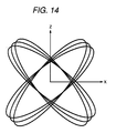
- the transmitter and receiver RF coils may comprise a single coil. Alternatively, two separate coils that are electrically orthogonal may be used. The latter configuration has the advantage of reduced RF pulse breakthrough into the receiver during pulse transmission. In both cases, the coils are orthogonal to the direction of the static magnetic field B o produced by magnet 428 (Fig. 11). The coils are isolated from the remainder of the system by enclosure in an RF shielded cage. Three typical RF coil designs are illustrated in FIGS. 12, 13, and 14. All of these coils produce RF magnetic fields in the x direction. The coil designs illustrated in FIGS. 13 and 14 are suitable for magnetic geometries for which the axis of the sample chamber is parallel to the main field B o (Fig. 1). The design illustrated in Fig. 12 is applicable to geometries for which the sample chamber axis is perpendicular to the main field B o (not shown).
- Magnetic field gradient coils 416, 418, and 420 are necessary to provide gradients G x , G y , and G z , respectively.
- the gradients should be monotonic and linear over the sample volume.
- Multivalued gradient fields cause a degradation in the NMR signal data, known as aliasing, which leads to severe image artifacts.
- Nonlinear gradients cause geometric distortions of the image.
- FIG. 5 An example of use of the present invention for the quantitative measurement of blood flow in the portal vein of a human subject is disclosed here.
- each subject's abdomen was compressed with a wide strap. Subjects were instructed to exhale and then hold their breath during the non-cardiac gated scans but were allowed to breath normally during the gated acquisitions.
- a 128 x 256 localization scan was performed first to determine the approximate location and orientation of the portal vein.
- the localization scan employed could be a multiple slice gradient recalled echo sequence which is fast enough to permit the acquisition of at least 6 coronal images in a single 20 second breath hold.
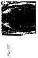
- the localizer image, Fig. 15 was then examined and the displacement (with respect to the center of the magnet) of the portal vein was determined.
- the rf waveform 62 (Fig.
- the Fourier flow encoding procedure was then applied using the same cylindrical excitation geometry. Data were acquired in a single breath-hold with flow encoding gradients 61, 71 (Fig. 3) applied parallel to the portal vein. The resultant image is shown in Fig. 17. It will be noted that the Inferior Vena Cava (IVC) and the portal vein both have a negative velocity, indicating the direction of flow.
- IVC Inferior Vena Cava
- a velocity V z vs. displacement X plot can be constructed as shown in Fig. 18.
- Fourier velocity encoded images such as those presented here can be used to measure several hemodynamic properties of blood flow.
- the maximum velocity within a vessel is easily determined by finding the pixel within the limits of the vessel which has the greatest displacement in the velocity dimension. Since the intensity of each pixel in a velocity image is proportional to the number of spins moving at a given velocity and in a given location, the mean velocity and the width of the velocity distribution can be easily determined. This can be done for each point in the spatially encoded dimension or over the entire vessel.
- the width of the vessel can be determined in the readout direction, but if its cross section is non-circular or if the readout gradient is applied obliquely, a conventional image may be required for the determination of vessel cross-section. Once the cross sectional area is known, the total flow in the vessel can easily be determined.
- the present invention provides a method of NMR imaging of molecules having motion, while suppressing images of molecules having no motion.
- the present invention can also suppress images of molecules in motion described by first order differentials or images of molecules which are not moving while imaging molecules described by second order differentials of motion and high order differentials of motion.
Landscapes
- Health & Medical Sciences (AREA)
- Physics & Mathematics (AREA)
- Life Sciences & Earth Sciences (AREA)
- Engineering & Computer Science (AREA)
- General Health & Medical Sciences (AREA)
- Signal Processing (AREA)
- Physiology (AREA)
- Public Health (AREA)
- Veterinary Medicine (AREA)
- Nuclear Medicine, Radiotherapy & Molecular Imaging (AREA)
- Biophysics (AREA)
- Pathology (AREA)
- Biomedical Technology (AREA)
- Heart & Thoracic Surgery (AREA)
- Medical Informatics (AREA)
- Molecular Biology (AREA)
- Surgery (AREA)
- Animal Behavior & Ethology (AREA)
- Psychiatry (AREA)
- Computer Vision & Pattern Recognition (AREA)
- Artificial Intelligence (AREA)
- Hematology (AREA)
- Cardiology (AREA)
- Mathematical Physics (AREA)
- Vascular Medicine (AREA)
- Radiology & Medical Imaging (AREA)
- High Energy & Nuclear Physics (AREA)
- Condensed Matter Physics & Semiconductors (AREA)
- General Physics & Mathematics (AREA)
- Magnetic Resonance Imaging Apparatus (AREA)
- Indicating Or Recording The Presence, Absence, Or Direction Of Movement (AREA)
Claims (12)
- Procédé de mesure quantitative du débit d'un fluide dans le vaisseau d'un sujet, comprenant les étapes consistant à :a) appliquer un champ magnétique homogène sur ledit sujet,b) effectuer une pluralité de balayages dudit sujet afin d'acquérir un ensemble de données de balayage, chaque balayage comprenant les étapes consistant à :- appliquer une excitation cylindrique audit sujet,- procéder à un codage de débit de la partie cylindrique excitée du sujet, par application d'une impulsion de gradient magnétique de codage du débit suivant l'axe du flux à mesurer, cette impulsion de gradient magnétique de codage du débit ayant une amplitude prédéterminée, qui varie d'une valeur maximale positive pour le balayage initial à une valeur maximale négative pour le balayage final, ou bien d'une valeur maximale négative pour le balayage initial à une valeur maximale positive pour le balayage final, et comprenant au moins un lobe négatif et au moins un lobe positif,- recueillir un ensemble de données de balayage, en :. appliquant audit sujet une première impulsion de gradient de champ magnétique de lecture,. appliquant audit sujet une seconde impulsion de gradient de champ magnétique de lecture, dont la superficie sous la courbe d'amplitude en fonction du temps est supérieure ou égale à celle de la première impulsion de gradient de champ magnétique de lecture, mais de polarité contraire,. détecter la quantité de signal de résonance magnétique (RM) ré-émise par la partie cylindrique excitée dudit sujet sur une période de temps donnée, en présence des impulsions de gradient de champ magnétique de lecture, et. mémoriser un ensemble de données de balayage relatives au signal RM ré-émis par le sujet qui concernent l'amplitude prédéterminée correspondante de l'impulsion de gradient magnétique de codage du débit,c) et reconstruire les données de balayage afin de déterminer ledit débit de fluide, en :- faisant subir une transformation de Fourier dans deux dimensions aux données de balayage afin de reconstruire un profil de déplacement du fluide,- déterminer le diamètre de section dudit vaisseau à partir des données de balayage, et- calculer ledit débit de fluide à partir du diamètre de section et du profil de déplacement du fluide.
- Procédé de mesure quantitative d'un débit de fluide dans un sujet selon la revendication 1, dans lequel l'application d'une excitation cylindrique comprend les étapes consistant à :- appliquer deux gradients de champ magnétique variant dans le temps, simultanés mais orthogonaux entre eux, audit sujet de telle sorte que les gradients créent un vecteur gradient résultant qui trace une spirale dans l'espace k, et- appliquer une impulsion d'excitation de radiofréquence audit sujet, l'impulsion de radiofréquence ayant une amplitude et une durée qui correspondent aux champs magnétiques orthogonaux variant dans le temps de façon à provoquer une résonance magnétique, ou excitation de noyaux prédéterminés dans la partie généralement cylindrique dudit sujet.
- Procédé de mesure quantitative d'un débit de fluide dans un sujet selon la revendication 1, dans lequel le gradient magnétique de codage du débit n'a que deux lobes, le premier lobe de l'impulsion de gradient magnétique de codage du débit ayant une amplitude prédéterminée qui varie d'une valeur maximale positive pour le balayage initial à une valeur maximale négative pour le balayage final, ou bien d'une valeur maximale négative pour le balayage initial à une valeur maximale positive pour le balayage final, et le second lobe de l'impulsion de gradient magnétique de codage du débit ayant une amplitude opposée, avec la même superficie sous sa courbe d'amplitude en fonction de la durée que le premier lobe, le gradient magnétique de codage du débit provoquant un codage dudit fluide en mouvement qui est décrit par des différentielles du premier ordre, ou d'un ordre supérieur, dans la partie cylindrique excitée du sujet.
- Procédé de mesure quantitative d'un débit de fluide dans un sujet selon la revendication 3, dans lequel les balayages de ladite pluralité sont synchronisés pour correspondre à un point particulier du cycle cardiaque d'un sujet vivant afin de créer un profil de vitesse instantané.
- Procédé de mesure quantitative d'un débit de fluide dans un sujet selon la revendication 4, incluant l'étape de reconstruction, à partir d'un ensemble de données de balayage recueillies au cours desdits balayages, d'images instantanées du flux qui correspondent à une partie particulière du cycle cardiaque.
- Procédé de mesure quantitative d'un débit de fluide dans un sujet selon la revendication 5, incluant l'étape d'affichage des images instantanées du flux de façon séquentielle, afin de produire une visualisation en mouvement des images du flux.
- Procédé de mesure quantitative d'un débit de fluide dans un sujet selon la revendication 2, comprenant en outre l'étape de détermination d'un emplacement à mesurer dudit sujet, grâce à l'utilisation de techniques classiques d'imagerie par résonance magnétique, puis de confinement de l'excitation cylindrique audit emplacement afin d'obtenir une mesure plus fine.
- Procédé de mesure quantitative d'un débit de fluide dans un sujet selon la revendication 2, dans lequel l'impulsion de gradient magnétique de codage du débit comporte trois lobes tels que la superficie sous la courbe de l'amplitude en fonction du temps du premier lobe et du troisième lobe est égale à celle du second lobe, et que la superficie sous la courbe de l'amplitude en fonction de la durée du second lobe est l'opposée de la superficie totale sous la courbe de l'amplitude en fonction de la durée des premier et troisième lobes, de façon à coder le débit de fluide dans la partie cylindrique excitée dudit sujet qui se déplace suivant la direction du gradient magnétique de codage du débit, le mouvement dudit fluide étant décrit par des différentielles, du premier ordre ou d'un ordre supérieur, de la vitesse par rapport au temps.
- Procédé de mesure quantitative d'un débit de fluide dans un sujet selon la revendication 2, incluant en outre l'étape d'application au cylindre excité, après l'excitation cylindrique et avant de recueillir les données de balayage, d'une impulsion de radiofréquence d'amplitude prédéterminé, pour provoquer une rotation de 180 degrés des spins par rapport à leurs positions avant application de l'impulsion de radiofréquence afin d'annuler des erreurs produites par l'homogénéité du champ magnétique.
- Procédé de mesure quantitative d'un débit de fluide dans un sujet selon la revendication 2, incluant en outre l'étape d'application d'une impulsion de radiofréquence d'amplitude prédéterminée et d'une impulsion de gradient d'amplitude prédéterminée pour que les spins d'une région choisie deviennent saturés et ne contribuent plus au signal observé.
- Procédé de mesure quantitative d'un débit de fluide dans un sujet selon la revendication 2, dans lequel l'impulsion d'excitation de radiofréquence et deux impulsions de gradient de champ magnétique orthogonales entre elles sont choisies pour exciter un volume de forme arbitraire dans deux dimensions et d'étendue infinie dans la troisième dimension.
- Procédé de mesure quantitative d'un débit de fluide dans un sujet selon la revendication 11, dans lequel l'impulsion d'excitation de radiofréquence et trois impulsions de gradient de champ magnétique orthogonales entre elles sont choisies pour exciter un volume de forme arbitraire dans trois dimensions.
Applications Claiming Priority (2)
| Application Number | Priority Date | Filing Date | Title |
|---|---|---|---|
| US651872 | 1984-09-18 | ||
| US07/651,872 US5133357A (en) | 1991-02-07 | 1991-02-07 | Quantitative measurement of blood flow using cylindrically localized fourier velocity encoding |
Publications (3)
| Publication Number | Publication Date |
|---|---|
| EP0498570A2 EP0498570A2 (fr) | 1992-08-12 |
| EP0498570A3 EP0498570A3 (en) | 1993-04-14 |
| EP0498570B1 true EP0498570B1 (fr) | 1996-04-03 |
Family
ID=24614566
Family Applications (1)
| Application Number | Title | Priority Date | Filing Date |
|---|---|---|---|
| EP92300819A Expired - Lifetime EP0498570B1 (fr) | 1991-02-07 | 1992-01-30 | Mesure quantitative du flux sanguin utilisant le codage de la vitesse par fourier cylindrique localisé |
Country Status (4)
| Country | Link |
|---|---|
| US (1) | US5133357A (fr) |
| EP (1) | EP0498570B1 (fr) |
| JP (1) | JPH0724656B2 (fr) |
| DE (1) | DE69209548D1 (fr) |
Families Citing this family (41)
| Publication number | Priority date | Publication date | Assignee | Title |
|---|---|---|---|---|
| US5227724A (en) * | 1991-06-06 | 1993-07-13 | The United States Of America As Represented By The Secretary Of The Navy | Pulsed-gradient spin diffusion NMR method |
| US5185574A (en) * | 1991-08-09 | 1993-02-09 | Mayo Foundation For Medical Education And Research | NMR measurements using recursive RF excitation |
| US5206591A (en) * | 1991-10-23 | 1993-04-27 | Siemens Aktiengesellschaft | Method for obtaining data in phase-contrast MR angiography |
| US5271399A (en) * | 1991-11-27 | 1993-12-21 | Trustees Of The University Of Pennsylvania | Three dimensional Fourier transform, fast spin echo, black blood magnetic resonance angtography |
| US5233298A (en) * | 1992-02-20 | 1993-08-03 | General Electric Company | Quantitative measurement of blood flow at multiple positions using comb excitation and fourier velocity encoding |
| US5309099A (en) * | 1992-08-07 | 1994-05-03 | The Board Of Trustees Of The Leland Stanford Junior University | Method of determining real-time spatially localized velocity distribution using magnetic resonance measurements |
| US5277192A (en) * | 1992-09-18 | 1994-01-11 | General Electric Company | Imaging of turbulence with magnetic resonance |
| US5307812A (en) * | 1993-03-26 | 1994-05-03 | General Electric Company | Heat surgery system monitored by real-time magnetic resonance profiling |
| US5363042A (en) * | 1993-08-12 | 1994-11-08 | General Electric Company | Methods for measurement of longitudinal spin relaxation times in moving liquids |
| JP3366398B2 (ja) | 1993-10-25 | 2003-01-14 | 株式会社日立メディコ | Mri装置 |
| US5436562A (en) * | 1993-12-29 | 1995-07-25 | General Electric Company | Methods for the simultaneous detection of multiple components of motion in moving fluids |
| US5410248A (en) * | 1993-12-29 | 1995-04-25 | General Electric Company | Method for the simultaneous detection of velocity and acceleration distribution in moving fluids |
| US5469059A (en) * | 1993-12-30 | 1995-11-21 | General Electric Company | Method for the simultaneous detection of acceleration and velocity distribution in moving fluids |
| US5517116A (en) * | 1993-12-30 | 1996-05-14 | General Electric Company | Method for the simultaneous detection of multiple components of velocity in moving fluids |
| DE19529512C2 (de) * | 1995-08-10 | 2000-11-23 | Siemens Ag | Verfahren zur Phasenkontrast-MR-Angiographie und Anordnung zur Durchführung des Verfahrens |
| US5604435A (en) * | 1995-12-29 | 1997-02-18 | General Electric Company | Spiral scanning method for monitoring physiological changes |
| US6141578A (en) * | 1998-04-08 | 2000-10-31 | General Electric Company | Method for calculating wave velocities in blood vessels |
| US6188922B1 (en) * | 1999-01-08 | 2001-02-13 | Wisconsin Alumni Research Foundation | Phase contrast imaging using interleaved projection data |
| DE19957754A1 (de) * | 1999-12-01 | 2001-06-07 | Philips Corp Intellectual Pty | MR-Verfahren zur Erzeugung von Navigatorimpulsen |
| US6998841B1 (en) * | 2000-03-31 | 2006-02-14 | Virtualscopics, Llc | Method and system which forms an isotropic, high-resolution, three-dimensional diagnostic image of a subject from two-dimensional image data scans |
| JP3858191B2 (ja) * | 2000-10-31 | 2006-12-13 | ジーイー・メディカル・システムズ・グローバル・テクノロジー・カンパニー・エルエルシー | Mri装置 |
| US6618609B2 (en) * | 2001-03-30 | 2003-09-09 | Koninklifke Philips Electronics, N.V. | Flow adaptive guided determination of imaging parameters for 3D magnetic resonance angiography |
| US6546275B2 (en) * | 2001-06-25 | 2003-04-08 | Wisconsin Alumni Research Foundation | Determination of the arterial input function in dynamic contrast-enhanced MRI |
| US6507749B1 (en) * | 2001-07-18 | 2003-01-14 | Sunnybrook And Women's College | Method and apparatus for tracking the motion of fluid and determining a velocity spectrum thereof from MR data acquired in a single cycle |
| US6650115B2 (en) * | 2001-10-12 | 2003-11-18 | The Board Of Trustees Of The Leland Stanford Junior University | Variable density fourier velocity encoding MR imaging |
| DE10256208B4 (de) * | 2002-12-02 | 2008-05-15 | Siemens Ag | Verfahren zur verbesserten Flussmessung in der Magnetresonanz-Tomographie |
| US6922580B2 (en) * | 2002-06-04 | 2005-07-26 | Koninklijke Philips Electronics N.V. | Blood flow gated MRI |
| US7027853B2 (en) * | 2002-09-26 | 2006-04-11 | Board Of Regents, The University Of Texas System | Data acquisition method and apparatus for MR imaging |
| US7227359B2 (en) * | 2003-11-26 | 2007-06-05 | Boards Of Regents, The University Of Texas System | Method and apparatus for phase-sensitive magnetic resonance imaging |
| CN100479748C (zh) * | 2004-03-26 | 2009-04-22 | 株式会社东芝 | 核磁共振成像装置 |
| US7307419B2 (en) * | 2004-12-20 | 2007-12-11 | General Electric Company | Method and system for spatial-spectral excitation by parallel RF transmission |
| US7333848B2 (en) * | 2005-02-02 | 2008-02-19 | Vassol Inc. | Method and system for evaluating vertebrobasilar disease |
| JP5305785B2 (ja) * | 2008-08-25 | 2013-10-02 | ジーイー・メディカル・システムズ・グローバル・テクノロジー・カンパニー・エルエルシー | 磁気共鳴イメージング装置および磁気共鳴イメージング装置の制御方法 |
| DE102009057721B4 (de) * | 2009-12-10 | 2014-05-28 | Siemens Aktiengesellschaft | Phasensensitive MR-Flussmessung |
| US20110175612A1 (en) * | 2010-01-13 | 2011-07-21 | Eissa Amir | Magnetic resonance imaging with independent excitation and acquisition volumes |
| US8738113B2 (en) | 2010-09-30 | 2014-05-27 | University Of Utah Research Foundation | Retrospectively correlated turbo spin echo imaging |
| DE102012217227B4 (de) | 2012-09-25 | 2014-05-15 | Siemens Aktiengesellschaft | MR-Phasenkontrastangiographie mit rotierenden Kodierungsgradienten |
| KR101560463B1 (ko) * | 2013-12-30 | 2015-10-16 | 가천대학교 산학협력단 | 오프 공명 라디오주파수 펄스를 사용하는 자기 공명 영상 시스템에서 인공물 및 원하지 않는 신호를 제거하는 자기 공명 영상 획득 방법 |
| US9594144B2 (en) | 2014-04-23 | 2017-03-14 | General Electric Company | Low-noise magnetic resonance imaging using low harmonic pulse sequences |
| JPWO2016009844A1 (ja) * | 2014-07-15 | 2017-04-27 | 株式会社日立製作所 | 磁気共鳴撮像装置及び血流描画方法 |
| DE102015223658B4 (de) * | 2015-11-30 | 2017-08-17 | Siemens Healthcare Gmbh | Verfahren zum Erfassen von Magnetresonanz-Signalen eines Untersuchungsobjekts |
Family Cites Families (6)
| Publication number | Priority date | Publication date | Assignee | Title |
|---|---|---|---|---|
| US4431968A (en) * | 1982-04-05 | 1984-02-14 | General Electric Company | Method of three-dimensional NMR imaging using selective excitation |
| DE3605990A1 (de) * | 1986-02-25 | 1987-09-03 | Spectrospin Ag | Verfahren zum bestimmen fliessenden materials mittels nmr-tomographie |
| US4796635A (en) * | 1987-02-11 | 1989-01-10 | General Electric Company | Multiple-echo, multiple-view NMR angiography |
| US4947120A (en) * | 1988-02-05 | 1990-08-07 | Massachusetts Institute Of Technology | Quantitative nuclear magnetic resonance imaging of flow |
| US4849697A (en) * | 1988-06-27 | 1989-07-18 | General Electric Company | Three-dimensional magnetic resonance flow-contrast angiography with suppression of stationary material |
| US4995394A (en) * | 1989-08-11 | 1991-02-26 | General Electric Company | Fast NMR cardiac profile imaging |
-
1991
- 1991-02-07 US US07/651,872 patent/US5133357A/en not_active Expired - Fee Related
-
1992
- 1992-01-30 EP EP92300819A patent/EP0498570B1/fr not_active Expired - Lifetime
- 1992-01-30 DE DE69209548T patent/DE69209548D1/de not_active Expired - Lifetime
- 1992-02-05 JP JP4047714A patent/JPH0724656B2/ja not_active Expired - Lifetime
Also Published As
| Publication number | Publication date |
|---|---|
| JPH06121782A (ja) | 1994-05-06 |
| DE69209548D1 (de) | 1996-05-09 |
| EP0498570A3 (en) | 1993-04-14 |
| EP0498570A2 (fr) | 1992-08-12 |
| US5133357A (en) | 1992-07-28 |
| JPH0724656B2 (ja) | 1995-03-22 |
Similar Documents
| Publication | Publication Date | Title |
|---|---|---|
| US5133357A (en) | Quantitative measurement of blood flow using cylindrically localized fourier velocity encoding | |
| US5233298A (en) | Quantitative measurement of blood flow at multiple positions using comb excitation and fourier velocity encoding | |
| US6954067B2 (en) | Three-dimensional phase contrast imaging using interleaved projection data | |
| USRE48347E1 (en) | Method and apparatus for spin-echo-train MR imaging using prescribed signal evolutions | |
| US9529066B2 (en) | Spatially encoded phase-contrast MRI | |
| US8060180B2 (en) | Multi-echo magnetic resonance imaging method and system | |
| US6393313B1 (en) | Producing a phase contrast MR image from a partial Fourier data acquisition | |
| US4714081A (en) | Methods for NMR angiography | |
| CN101884534B (zh) | 磁共振断层造影中无造影剂的血管造影成像方法 | |
| US8148984B2 (en) | Method for magnitude constrained phase contrast magnetic resonance imaging | |
| US4715383A (en) | Method for reducing artifacts in NMR images | |
| EP0126381A1 (fr) | Mesurage et image de flux liquide au moyen de la résonance magnétique nucléaire | |
| US7049816B2 (en) | Magnetic resonance imaging with dual velocity encoded projection reconstruction acquisition | |
| US20130300410A1 (en) | Method for fast spin-echo MRT imaging | |
| Dumoulin et al. | Quantitative measurement of blood flow using cylindrically localized Fourier velocity encoding | |
| USRE45725E1 (en) | Method and apparatus for spin-echo-train MR imaging using prescribed signal evolutions | |
| JPH08507614A (ja) | 移動流体の速度および加速度分布の同時検出方法 | |
| Faulkner Jr | Rad tech's guide to MRI: basic physics, instrumentation, and quality control | |
| Lipton et al. | Magnetic resonance angiography | |
| Barbadillo | Pulmonary blood volume measurement by contrast magnetic resonance imaging: a system identification | |
| Stehning et al. | Fast whole-heart coronary MRA using 3D-radial SSFP with 32 channel parallel acquisition and self-navigated image reconstruction | |
| Kim et al. | Department of Radiology, Utah Center for Advanced Imaging Research University of Utah, Salt Lake City, Utah | |
| SLICE-SELECTION | Frequency Encoding: Position in X | |
| Mendes | Motion compensation in Turbo Spin Echo angiography |
Legal Events
| Date | Code | Title | Description |
|---|---|---|---|
| PUAI | Public reference made under article 153(3) epc to a published international application that has entered the european phase |
Free format text: ORIGINAL CODE: 0009012 |
|
| AK | Designated contracting states |
Kind code of ref document: A2 Designated state(s): DE FR GB NL |
|
| PUAL | Search report despatched |
Free format text: ORIGINAL CODE: 0009013 |
|
| AK | Designated contracting states |
Kind code of ref document: A3 Designated state(s): DE FR GB NL |
|
| 17P | Request for examination filed |
Effective date: 19930930 |
|
| 17Q | First examination report despatched |
Effective date: 19950404 |
|
| GRAA | (expected) grant |
Free format text: ORIGINAL CODE: 0009210 |
|
| AK | Designated contracting states |
Kind code of ref document: B1 Designated state(s): DE FR GB NL |
|
| PG25 | Lapsed in a contracting state [announced via postgrant information from national office to epo] |
Ref country code: NL Free format text: LAPSE BECAUSE OF FAILURE TO SUBMIT A TRANSLATION OF THE DESCRIPTION OR TO PAY THE FEE WITHIN THE PRESCRIBED TIME-LIMIT Effective date: 19960403 Ref country code: FR Effective date: 19960403 |
|
| REF | Corresponds to: |
Ref document number: 69209548 Country of ref document: DE Date of ref document: 19960509 |
|
| PG25 | Lapsed in a contracting state [announced via postgrant information from national office to epo] |
Ref country code: DE Effective date: 19960704 |
|
| EN | Fr: translation not filed | ||
| NLV1 | Nl: lapsed or annulled due to failure to fulfill the requirements of art. 29p and 29m of the patents act | ||
| PG25 | Lapsed in a contracting state [announced via postgrant information from national office to epo] |
Ref country code: GB Effective date: 19970130 |
|
| PLBE | No opposition filed within time limit |
Free format text: ORIGINAL CODE: 0009261 |
|
| 26N | No opposition filed | ||
| GBPC | Gb: european patent ceased through non-payment of renewal fee |
Effective date: 19970130 |