EP0498848B1 - Jeu de briques profilees et brique profilee pour le revetement superficiel de sols a joints larges - Google Patents
Jeu de briques profilees et brique profilee pour le revetement superficiel de sols a joints larges Download PDFInfo
- Publication number
- EP0498848B1 EP0498848B1 EP90917114A EP90917114A EP0498848B1 EP 0498848 B1 EP0498848 B1 EP 0498848B1 EP 90917114 A EP90917114 A EP 90917114A EP 90917114 A EP90917114 A EP 90917114A EP 0498848 B1 EP0498848 B1 EP 0498848B1
- Authority
- EP
- European Patent Office
- Prior art keywords
- shaped
- stones
- stone
- shaped stones
- partial
- Prior art date
- Legal status (The legal status is an assumption and is not a legal conclusion. Google has not performed a legal analysis and makes no representation as to the accuracy of the status listed.)
- Expired - Lifetime
Links
Images


Classifications
-
- E—FIXED CONSTRUCTIONS
- E01—CONSTRUCTION OF ROADS, RAILWAYS, OR BRIDGES
- E01C—CONSTRUCTION OF, OR SURFACES FOR, ROADS, SPORTS GROUNDS, OR THE LIKE; MACHINES OR AUXILIARY TOOLS FOR CONSTRUCTION OR REPAIR
- E01C5/00—Pavings made of prefabricated single units
- E01C5/06—Pavings made of prefabricated single units made of units with cement or like binders
-
- E—FIXED CONSTRUCTIONS
- E01—CONSTRUCTION OF ROADS, RAILWAYS, OR BRIDGES
- E01C—CONSTRUCTION OF, OR SURFACES FOR, ROADS, SPORTS GROUNDS, OR THE LIKE; MACHINES OR AUXILIARY TOOLS FOR CONSTRUCTION OR REPAIR
- E01C9/00—Special pavings; Pavings for special parts of roads or airfields
- E01C9/004—Pavings specially adapted for allowing vegetation
-
- E—FIXED CONSTRUCTIONS
- E01—CONSTRUCTION OF ROADS, RAILWAYS, OR BRIDGES
- E01C—CONSTRUCTION OF, OR SURFACES FOR, ROADS, SPORTS GROUNDS, OR THE LIKE; MACHINES OR AUXILIARY TOOLS FOR CONSTRUCTION OR REPAIR
- E01C2201/00—Paving elements
- E01C2201/02—Paving elements having fixed spacing features
-
- E—FIXED CONSTRUCTIONS
- E01—CONSTRUCTION OF ROADS, RAILWAYS, OR BRIDGES
- E01C—CONSTRUCTION OF, OR SURFACES FOR, ROADS, SPORTS GROUNDS, OR THE LIKE; MACHINES OR AUXILIARY TOOLS FOR CONSTRUCTION OR REPAIR
- E01C2201/00—Paving elements
- E01C2201/06—Sets of paving elements
-
- E—FIXED CONSTRUCTIONS
- E01—CONSTRUCTION OF ROADS, RAILWAYS, OR BRIDGES
- E01C—CONSTRUCTION OF, OR SURFACES FOR, ROADS, SPORTS GROUNDS, OR THE LIKE; MACHINES OR AUXILIARY TOOLS FOR CONSTRUCTION OR REPAIR
- E01C2201/00—Paving elements
- E01C2201/16—Elements joined together
Definitions
- the invention relates to a molded block set and a covering element for covering floor areas with wide joints between the molded blocks or covering elements.
- Such shaped stones are often referred to as "lawn paving stones". They have spacing projections on their circumference, so that comparatively wide joints are created between the stones in the occupied area. Soil can be placed in these joints, and grass can grow in the wide, earth-filled joints. This gives the occupied area a pleasant, natural look, and yet the occupied area is fixed and can be driven on by vehicles. Alternatively, it is possible to fill the wide joints with, for example, relatively coarse sand or fine grit or stone chips. In both cases, it follows that at least a large part of surface water enters the spaces between the stones and does not have to be drained into a sewage system along the surface of the occupied area.
- the described lawn paving stones are to be distinguished from so-called lawn grating slabs, which have internal openings or openings for the formation of grass there.
- Such a stone insert is known from document DE-A-38 04 760.
- the stones of all existing stone types are provided with integral spacing projections.
- a floor surface covered with the shaped stones of the shaped stone set offers a lively, pleasing appearance because not a single shaped stone format recurs monotonously.
- the wide joints do not run in a straight line or - for example because of the non-straight stone contour - only slightly deviate from the straight line, but you get joints that are considerably laterally branching. This improves the accessibility of the occupied floor area, which is particularly important in view of the wide joints.
- the manufacturability of the molded block set is made easier and cheaper because only the molded blocks of one of the two molded block types with the more difficult to produce spacer projections are provided.
- Such a covering element is known from document DE-A-27 32 452.
- this covering element no spacing projections are provided on the outer circumference.
- first shaped stones or partial shaped stones and second shaped stones or partial shaped stones of the same geometric shape for example a larger square with a smaller square, a larger hexagon with a smaller hexagon, a larger octagon with a smaller octagon, a larger circle with a smaller circle, the design mentioned is aimed at a change in the basic geometric shape.
- the side length of the square is preferably correct essentially correspond to the length of the octagon side that faces the square, possibly in the installed state.
- the length dimensioning of the spacing projections mentioned in claims 6 and 14 leads to the fact that, despite the size difference in the top view surface between the first molded block or partial molded block and the second molded block or partial molded block, straight boundary lines in the case of an occupied floor area or in a group of juxtaposed shaped stones or covering elements arise.
- the last-mentioned effect is important because it enables a group of shaped blocks or covering elements to be lifted comfortably and safely using mechanical clamping grippers and can be installed mechanically at the same time.
- the covering element according to the invention designed as a molded block, can also have a plurality of first molded blocks and a plurality of second molded blocks, so that, for example, integral arrangements of 4, 6, 8, etc. molded blocks can be formed.
- the shaped stone insert or covering element according to the invention can also have more than two shaped stone formats or partial shaped stone formats, for example three or four different formats.
- the shaped stone set or covering element according to the invention preferably consists of concrete, but can also consist of other suitable materials that can be shaped in the raw state, for example brick material, sand-lime brick material, etc.
- the invention relates to a floor covering made of shaped stones with wide joints between the shaped stones, which has a plurality of rows of adjoining shaped stones, characterized in that, when proceeding both in the row direction and transversely to the row direction, first shaped stones according to the invention and second shaped stones according to the invention of the shaped stone insert after one of claims 1 to 8 alternate with each other.
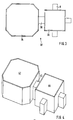
- the shaped stone set 2 shown in FIGS. 1 and 2 consists of an octagonal, first shaped stone 4 in plan view and a second shaped stone 6, which is square in plan view with a rectangular spacing projection 8 on each side of the square.
- the top view octagon of the first shaped block 4 is centrally symmetrical, with longer sides 10 of the octagon alternating with shorter sides 12 of the octagon.
- the sides 14 of the top view square of the second shaped block 6 are essentially the same length as the longer sides 10 of the first shaped block 4.
- first shaped block 4 and the second shaped block 6 in FIGS. 1 and 2 are drawn with a free space between them. It goes without saying that the shaped blocks are laid so close together to cover a floor surface that the end of a spacing projection 8 abuts against the center of a longer side 10 of the first shaped block 4.
- the upper sides 24 of the spacer projections 8 lie below the level of the useful sides 16 and 18 and run parallel to this. Instead of the parallel course, one can in particular also provide that the upper sides 24 are bevelled outward-downward or in alignment with the useful side 18 or that the upper sides 24 are gable roof-shaped with a ridge line running radially outward from the center of the second shaped block 6.
- a possible variant is to also form the second shaped block 6 in plan view with bevelled corners, so that it represents, so to speak, a version of the first shaped block 4 that has a smaller face size. Furthermore, it is alternatively possible to provide the spacing projections 8 on the first shaped stone 4 instead of on the second shaped stone 6. These variants are also possible analogously for the shaped blocks according to FIGS. 3 and 4.
- the variants of the top design of the spacing projections 8 described in connection with the first exemplary embodiment according to FIGS. 1 and 2 also apply here and analogously to the top design of the material bridge 38.
- 3 and 4 is the Material bridge 38 would be less wide than the length of a square side of the second partial shaped block 36. It is alternatively possible to make the material bridge 38 as wide as this side of the square is long. It is also possible to provide a plurality of material bridges 38 next to one another.
- octagonal, larger stone shapes alternate with square, smaller stone shapes regularly, both as they progress along a row 52 horizontally in FIG. 5 and at right angles thereto.
- Each square stone shape is surrounded on its four sides by four octagonal stone shapes; each octagonal stone shape is surrounded on four sides by square stone shapes (except that the shorter sides of the octagon face shorter sides of "diagonally" adjacent octagon stone shapes).
- the joints 50 if one proceeds horizontally or vertically in FIG. 5, jump considerably laterally, so that the Wheels of vehicles, for example passenger cars, do not come into positions where they only rest on joint edges. Rather, adjacent joint areas are offset so far that the wheel in question always rests on the useful stone sides.
- FIG. 6 shows a section of a corner area of a production mold 60, in horizontal section, for producing a plurality of molded blocks 32 according to FIGS. 3 and 4 on the horizontal table 62 of a molded concrete block production machine.
- This manufacturing mold 60 corresponds to the prior art, with the exception of the shape matched to the shaped stones to be produced in the present case.
- a shaped block 32 to be produced is shown at the top left in FIG. 6 and a further shaped block 32 to be produced below it in FIG. 6, the upper shaped block 32 with the first partial shaped block 34 being oriented to the left and the further shaped block 32 with its first Part-shaped block 34 is oriented to the right. Further subsequent shaped block 32 to be produced are shown broken off.
- the production mold 60 is either designed as a welded-together construction or burned out of solid material using a laser beam.
- the inner wall of the mold frame 64 and the inner mold regions 66 are designed such that shaping surfaces 68 are formed in accordance with the shaped stones 32 to be produced.
- the upper sides of the spacer projections 8 and the material bridges 38 as well as the useful sides 42, 44 the shaped block 32 are formed by a not shown, upward and downward movable die, which is pressed from above into the still soft concrete mass.
Landscapes
- Engineering & Computer Science (AREA)
- Architecture (AREA)
- Civil Engineering (AREA)
- Structural Engineering (AREA)
- Road Paving Structures (AREA)
- Road Paving Machines (AREA)
- Floor Finish (AREA)
- Finishing Walls (AREA)
Claims (20)
- Jeu de blocs pour revêtement de sols avec des joints (50) larges entre les blocs, présentant les caractéristiques suivantes :(a) le jeu de blocs comprend des premiers blocs (4) avec une grande surface de dessus et séparés de ceux-ci, des seconds blocs (6) avec une plus petite surface de dessus ;(b) certains de ces blocs (4, 6) étant pourvus sur leur pourtour de plusieurs reliefs d'écartement intégrés ;
caractérisé en ce que,(c) les blocs (4, 6) de l'un des deux types de blocs ne comportent pas de reliefs d'écartement (8) ;(d) seuls les blocs (4, 6) de l'autre des deux types de blocs sont pourvus des reliefs d'écartement (8) afin de définir les joints (50) larges dans le revêtement en blocs. - Jeu de blocs selon la revendication 1, caractérisé en ce que seuls les seconds blocs (6) sont pourvus des reliefs d'écartement (8).
- Jeu de blocs selon les revendications 1 ou 2, caractérisé en ce que la forme des premiers blocs (4) et la forme des seconds blocs (5) sont différentes.
- Jeu de blocs selon l'une des revendications 1 à 3, caractérisé en ce que les premiers blocs (4) vus de dessus sont des octogones, de préférence des octogones à symétrie centrale avec quatre grands côtés et quatre petits côtés.
- Jeu de blocs selon l'une des revendications 1 à 4, caractérisé en ce que les seconds blocs (6) vus de dessus sont carrés.
- Jeu de blocs selon l'une des revendications 2 à 5, caractérisé en ce que les reliefs d'écartement (8) des seconds blocs (6) dépassent de telle sorte que lorsqu'un second bloc (6) se trouve au milieu à côté d'un premier bloc (4), la paire de blocs peut s'inscrire dans un rectangle de contour commun, qui touche le premier bloc (4) sur le pourtour et les extrémités des reliefs d'écartement (8).
- Jeu de blocs selon l'une des revendications 1 à 6, caractérisé en ce que les faces supérieures (24) des reliefs d'écartement (8) se situent plus profondément que la face utile (18) du bloc (6) correspondant.
- Jeu de blocs selon l'une des revendications 1 à 7, caractérisé en ce que les reliefs d'écartement (8) sur leur face supérieure sont parallèles à la face utile (18) du bloc (6) correspondant ou s'étendent chanfreinés vers le bas et vers l'extérieur ou sont en forme de toit à pignon.
- Elément de revêtement pour le revêtement de sols qui-relié par un pont de matière (38) intégré - comporte au moins- un premier bloc partiel (34) avec une grande surface de dessus ; et- un second bloc partiel (36) avec une plus petite surface de dessus,caractérisé en ce que(a) l'élément de revêtement (32), conçu sous la forme d'un bloc (32), comporte sur son pourtour extérieur des reliefs d'écartement (8) intégrés définissant des joints (50) larges par rapport aux blocs (32) voisins ;(b) le bloc partiel (34, 36) de l'un des deux types de bloc partiel ne comporte pas de reliefs d'écartement (8) sur le pourtour extérieur ; et(c) en ce que les reliefs d'écartement (8) ne sont prévus que sur le bloc partiel (34, 36) de l'autre des deux types de bloc partiel.
- Elément de revêtement selon la revendication 9, caractérisé en ce que les reliefs d'écartement (8) ne sont prévus que sur le pourtour du second bloc partiel (36).
- Elément de revêtement selon les revendications 9 ou 10, caractérisé en ce que la forme du premier bloc partiel (34) et la forme du second bloc partiel (36) sont différentes.
- Elément de revêtement selon l'une des revendications 9 à 11, caractérisé en ce que le premier bloc partiel (34) vu de dessus est octogonal, de préférence octogonal avec symétrie centrale avec quatre grands côtés et quatre petits côtés.
- Elément de revêtement selon l'une des revendications 9 à 12, caractérisé en ce que le second bloc partiel (36) vu de dessus est carré.
- Elément de revêtement selon l'une des revendications 10 à 13, caractérisé en ce que l'élément de revêtement (32) est constitué d'un premier bloc partiel (34) et d'un second bloc partiel (36) et en ce que les reliefs d'écartement (8) sur le deuxième bloc (36) dépassent de manière que l'élément de revêtement (32) s'inscrit dans un rectangle de contour qui touche le premier bloc partiel (34) sur le pourtour et les extrémités des reliefs d'écartement (8).
- Elément de revêtement selon l'une des revendications 9 à 14, caractérisé en ce que le pont de matière (38), mesuré dans la direction tangentielle par rapport au milieu du second bloc partiel (36), est moins large que les zones périphériques tournées l'une vers l'autre du premier et du second blocs partiels 34, 36, mais de préférence plus large que la largeur des reliefs d'écartement 8.
- Elément de revêtement selon l'une des revendications 9 à 15, caractérisé en ce que le pont de matière (38), mesuré dans la direction radiale par rapport au milieu du second bloc partiel (36), est sensiblement de même longueur que les reliefs d'écartement (8).
- Elément de revêtement selon l'une des revendications 9 à 16, caractérisé en ce que les faces supérieures des reliefs d'écartement (8) et/ou du pont de matière (38) se situent plus profondément que la face utile de l'élément de revêtement (32).
- Elément de revêtement selon l'une des revendications 9 à 17, caractérisé en ce que les reliefs d'écartement (8) et/ou le pont de matière (38) sur leur face supérieure sont parallèles à la face utile de l'élément de revêtement (32) ou s'étendent chanfreinés vers le bas et l'extérieur ou sont en forme de toit à pignon.
- Moule de fabrication (60) métallique pour la fabrication simultanée de plusieurs blocs en béton sur la table d'une machine de fabrication de blocs en béton, caractérisé(a) en ce que le moule de fabrication (60) présente des surfaces de formage telles qu'il forme des jeux de blocs semblables entre eux selon l'une des revendications 1 à 8 ;(b) ou en ce que le moule de fabrication (60) présente des surfaces de formage telles qu'il forme des éléments de revêtement semblables entre eux selon l'une des revendications 9 à 18.
- Revêtement de sols fait de blocs (4, 6) avec joints (50) larges entre les blocs (4,. 6), qui comporte plusieurs rangées de blocs (4, 6) voisins, caractérisé en ce qu'en progressant dans la direction des rangées comme dans la direction transversale à celle-ci, des premiers blocs (4) et des seconds blocs du jeu de blocs selon l'une des revendications 1 à 8 alternent entre eux.
Applications Claiming Priority (3)
| Application Number | Priority Date | Filing Date | Title |
|---|---|---|---|
| DE3936527 | 1989-11-02 | ||
| DE3936527A DE3936527A1 (de) | 1989-11-02 | 1989-11-02 | Formsteinsatz und formstein zum belegen von bodenflaechen mit breiten fugen |
| SG127094A SG127094G (en) | 1989-11-02 | 1994-08-27 | Set of shaped bricks and shaped brick with broad joints for paving |
Publications (2)
| Publication Number | Publication Date |
|---|---|
| EP0498848A1 EP0498848A1 (fr) | 1992-08-19 |
| EP0498848B1 true EP0498848B1 (fr) | 1994-03-09 |
Family
ID=25886692
Family Applications (1)
| Application Number | Title | Priority Date | Filing Date |
|---|---|---|---|
| EP90917114A Expired - Lifetime EP0498848B1 (fr) | 1989-11-02 | 1990-10-26 | Jeu de briques profilees et brique profilee pour le revetement superficiel de sols a joints larges |
Country Status (14)
| Country | Link |
|---|---|
| US (1) | US5360285A (fr) |
| EP (1) | EP0498848B1 (fr) |
| JP (1) | JPH05504605A (fr) |
| AT (1) | ATE102673T1 (fr) |
| AU (1) | AU633659B2 (fr) |
| CA (1) | CA2072740C (fr) |
| DE (2) | DE3936527A1 (fr) |
| DK (1) | DK0498848T3 (fr) |
| ES (1) | ES2049992T3 (fr) |
| HK (1) | HK111894A (fr) |
| IL (1) | IL96140A0 (fr) |
| SG (1) | SG127094G (fr) |
| WO (1) | WO1991006706A1 (fr) |
| ZA (1) | ZA908769B (fr) |
Families Citing this family (18)
| Publication number | Priority date | Publication date | Assignee | Title |
|---|---|---|---|---|
| DE4341282A1 (de) * | 1993-12-03 | 1995-06-08 | Bkn Karl Boegl Gmbh & Co | Kunststeinsatz aus Kunststeinen unterschiedlicher Gestalt |
| DE4402281A1 (de) * | 1994-01-27 | 1995-08-10 | Sf Koop Gmbh Beton Konzepte | Verfahren und Vorrichtung zum Herstellen von Beton-Pflastersteinen |
| AU129484S (en) * | 1994-09-19 | 1997-03-25 | Uni Int Bausysteme G M B H Co | Paving block |
| US5556228A (en) * | 1995-02-06 | 1996-09-17 | Smith; Lee A. | Block for controlling soil erosion |
| DE19716938A1 (de) * | 1997-04-23 | 1998-10-29 | Sf Koop Gmbh Beton Konzepte | Formstein, Bausatz aus Formsteinen und Verfahren zur Herstellung eines Formsteins |
| USD431305S (en) * | 1997-04-23 | 2000-09-26 | F. Von Langsdorff Licensing Ltd. | Paving stone |
| DE29720206U1 (de) * | 1997-11-14 | 1998-01-02 | Betonwerk Kwade GmbH & Co. KG, 48465 Schüttorf | Formstein aus Beton für Pflasterungen |
| DE19851674A1 (de) * | 1998-11-10 | 2000-05-11 | Karl Weber Betonwerk Gmbh & Co | Baustein und daraus gebildetes Mauerwerk |
| DE10047975A1 (de) * | 2000-09-27 | 2002-05-16 | Karl Weber Betonwerk Gmbh & Co | Bodenbelagelementsatz aus einem grösseren, ersten Bodenbelagelement aus Kunststeinmaterial und einem kleineren, zweiten Bodenbelagelement aus Kunststeinmaterial |
| US20060159517A1 (en) * | 2005-01-18 | 2006-07-20 | Hagerman Joseph W | Core for paver and method |
| USD759843S1 (en) | 2008-12-01 | 2016-06-21 | F. Von Langsdorff Licensing Limited | Paving stone |
| CA130858S (en) | 2008-12-01 | 2010-10-13 | F Von Langsdorff Licensing Ltd | Paving stone |
| US9701046B2 (en) | 2013-06-21 | 2017-07-11 | Pavestone, LLC | Method and apparatus for dry cast facing concrete deposition |
| US10583588B2 (en) | 2013-06-21 | 2020-03-10 | Pavestone, LLC | Manufactured retaining wall block with improved false joint |
| USD791346S1 (en) | 2015-10-21 | 2017-07-04 | Pavestone, LLC | Interlocking paver |
| USD737468S1 (en) | 2014-05-07 | 2015-08-25 | Pavestone, LLC | Front face of a retaining wall block |
| AU2016356749B2 (en) | 2015-11-17 | 2021-12-16 | F. Von Langsdorff Licensing Limited | Paving element having drainage channels and pavement system incorporating same |
| USD1037491S1 (en) | 2021-12-14 | 2024-07-30 | Pavestone, LLC | Wall block |
Family Cites Families (10)
| Publication number | Priority date | Publication date | Assignee | Title |
|---|---|---|---|---|
| DE2732452A1 (de) * | 1977-07-18 | 1979-02-01 | Barth Kg Dr | Belagelement mit durch schwaechungszonen vorgebildeten einzelsteinen |
| DE2841261A1 (de) * | 1978-09-22 | 1980-04-03 | Walter Jaeger | Ornamentpflasterstein-bausatz |
| DE8013891U1 (de) * | 1980-05-23 | 1980-08-28 | Hoetzel-Beton Gmbh, 7514 Eggenstein- Leopoldshafen | Satz aus zwei verbundsteinen |
| DE3303225C2 (de) * | 1983-02-01 | 1987-02-05 | Hermann Dipl.-Ing. 6334 Werdorf Willeck | Betonpflastersteinverband sowie Betonpflasterstein für den Verband |
| DE3303210A1 (de) * | 1983-02-01 | 1984-08-02 | Hugo 8756 Kahl Rosenberger | Verlegeeinheit |
| DE3604760A1 (de) * | 1986-02-14 | 1987-08-20 | Hubert Eirich | Verfahren und vorrichtung zur konditionierung von kraftwerksreststoffen |
| US4834575A (en) * | 1986-09-23 | 1989-05-30 | Barth Guenther | Paving stone |
| DE3722683A1 (de) * | 1987-07-09 | 1989-01-26 | Kraemer Franz Gerd | Formstein aus beton oder aehnlichem material zum belegen von bodenflaechen |
| DE3804760A1 (de) * | 1988-02-16 | 1989-08-24 | Guido Wertebach | Rasenpflasterstein |
| DE8901920U1 (de) * | 1989-01-05 | 1989-06-08 | Sf-Vollverbundstein-Kooperation Gmbh, 2820 Bremen | Bausatz aus (Beton-)Formstein |
-
1989
- 1989-11-02 DE DE3936527A patent/DE3936527A1/de not_active Withdrawn
-
1990
- 1990-10-26 WO PCT/EP1990/001919 patent/WO1991006706A1/fr not_active Ceased
- 1990-10-26 CA CA002072740A patent/CA2072740C/fr not_active Expired - Lifetime
- 1990-10-26 ES ES90917114T patent/ES2049992T3/es not_active Expired - Lifetime
- 1990-10-26 US US07/854,663 patent/US5360285A/en not_active Expired - Lifetime
- 1990-10-26 JP JP3500093A patent/JPH05504605A/ja active Pending
- 1990-10-26 DK DK90917114.2T patent/DK0498848T3/da active
- 1990-10-26 EP EP90917114A patent/EP0498848B1/fr not_active Expired - Lifetime
- 1990-10-26 AU AU67527/90A patent/AU633659B2/en not_active Ceased
- 1990-10-26 DE DE90917114T patent/DE59004954D1/de not_active Expired - Fee Related
- 1990-10-26 AT AT90917114T patent/ATE102673T1/de active
- 1990-10-28 IL IL96140A patent/IL96140A0/xx not_active IP Right Cessation
- 1990-11-01 ZA ZA908769A patent/ZA908769B/xx unknown
-
1994
- 1994-08-27 SG SG127094A patent/SG127094G/en unknown
- 1994-10-12 HK HK111894A patent/HK111894A/xx not_active IP Right Cessation
Also Published As
| Publication number | Publication date |
|---|---|
| US5360285A (en) | 1994-11-01 |
| ATE102673T1 (de) | 1994-03-15 |
| ES2049992T3 (es) | 1994-05-01 |
| AU6752790A (en) | 1991-05-31 |
| CA2072740A1 (fr) | 1991-05-03 |
| SG127094G (en) | 1995-01-13 |
| CA2072740C (fr) | 1996-06-25 |
| JPH05504605A (ja) | 1993-07-15 |
| DE3936527A1 (de) | 1991-05-08 |
| HK111894A (en) | 1994-10-21 |
| AU633659B2 (en) | 1993-02-04 |
| ZA908769B (en) | 1991-08-28 |
| DK0498848T3 (da) | 1994-07-18 |
| EP0498848A1 (fr) | 1992-08-19 |
| WO1991006706A1 (fr) | 1991-05-16 |
| DE59004954D1 (de) | 1994-04-14 |
| IL96140A0 (en) | 1991-07-18 |
Similar Documents
| Publication | Publication Date | Title |
|---|---|---|
| EP0498848B1 (fr) | Jeu de briques profilees et brique profilee pour le revetement superficiel de sols a joints larges | |
| EP0465536B1 (fr) | Pierre angulaire pour consolider une surface | |
| EP1027500B1 (fr) | Pave, jeu de paves et dispositif de production correspondant | |
| EP0648291B1 (fr) | Pave avec elements d'espacement lateraux | |
| EP0377460A1 (fr) | Ensemble de construction constitué par des pavés en béton | |
| WO1997008389A1 (fr) | Pave en beton | |
| DE10149250A1 (de) | Formstein aus Beton und Bausatz aus Formsteinen zur Erstellung von Erdreichabdeckungen | |
| DE4036444A1 (de) | Plattenfoermiger pflasterstein | |
| EP1254285B1 (fr) | Jeu de construction compose de paves ou de plaques de beton | |
| EP0274344B1 (fr) | Jeu de pavés avec dentures perpendiculaires sur chaque côté, procédé de fabrication de tels pavés et application de pavés fabriqués | |
| DE2452475A1 (de) | Belagplatte, insbesondere betonplatte, vorzugsweise fuer strassen-, weg- oder platzdecken, die in mehrere plattenteile brechbar ist | |
| EP1170433B1 (fr) | Palissade en béton | |
| DE2235826A1 (de) | Pflastersteinsatz und verfahren zum verlegen solcher steine | |
| DE3804760A1 (de) | Rasenpflasterstein | |
| DE19521306A1 (de) | Betonpflasterstein samt Vorrichtungen und Verfahren zur Herstellung | |
| EP2331752B1 (fr) | Pavage de sol constitué de blocs moulés | |
| EP1181413B1 (fr) | Pave moule | |
| DE69920548T2 (de) | Verfahren zur Herstellung eines Satzes von Pflastersteinen und durch das Verfahren hergestellte Plastersteine | |
| DE10149230A1 (de) | Formstein aus Beton, Bausatz aus Formsteinen und Form zur Herstellung von Formsteinen | |
| DE19616622A1 (de) | Beton-Formstein, Bausatz aus Beton-Formsteinen sowie eine hieraus hergestellte Stützmauer | |
| DE19517662A1 (de) | Gruppe von Pflastersteinen | |
| DE202025107823U1 (de) | Betonformstein | |
| DE8123755U1 (de) | "verbundstein" | |
| DE29604736U1 (de) | Bodenplatte | |
| DE4446427A1 (de) | Pflasterstein aus Beton und Belag aus derartigen Pflastersteinen |
Legal Events
| Date | Code | Title | Description |
|---|---|---|---|
| PUAI | Public reference made under article 153(3) epc to a published international application that has entered the european phase |
Free format text: ORIGINAL CODE: 0009012 |
|
| 17P | Request for examination filed |
Effective date: 19920504 |
|
| AK | Designated contracting states |
Kind code of ref document: A1 Designated state(s): AT BE CH DE DK ES FR GB LI NL SE |
|
| 17Q | First examination report despatched |
Effective date: 19930622 |
|
| GRAA | (expected) grant |
Free format text: ORIGINAL CODE: 0009210 |
|
| RAP1 | Party data changed (applicant data changed or rights of an application transferred) |
Owner name: UNI-INTERNATIONAL BAUSYSTEME GMBH & CO. |
|
| AK | Designated contracting states |
Kind code of ref document: B1 Designated state(s): AT BE CH DE DK ES FR GB LI NL SE |
|
| REF | Corresponds to: |
Ref document number: 102673 Country of ref document: AT Date of ref document: 19940315 Kind code of ref document: T |
|
| REF | Corresponds to: |
Ref document number: 59004954 Country of ref document: DE Date of ref document: 19940414 |
|
| REG | Reference to a national code |
Ref country code: ES Ref legal event code: FG2A Ref document number: 2049992 Country of ref document: ES Kind code of ref document: T3 |
|
| ET | Fr: translation filed | ||
| GBT | Gb: translation of ep patent filed (gb section 77(6)(a)/1977) |
Effective date: 19940615 |
|
| REG | Reference to a national code |
Ref country code: DK Ref legal event code: T3 |
|
| PGFP | Annual fee paid to national office [announced via postgrant information from national office to epo] |
Ref country code: ES Payment date: 19940929 Year of fee payment: 5 |
|
| PLBE | No opposition filed within time limit |
Free format text: ORIGINAL CODE: 0009261 |
|
| STAA | Information on the status of an ep patent application or granted ep patent |
Free format text: STATUS: NO OPPOSITION FILED WITHIN TIME LIMIT |
|
| EAL | Se: european patent in force in sweden |
Ref document number: 90917114.2 |
|
| 26N | No opposition filed | ||
| PG25 | Lapsed in a contracting state [announced via postgrant information from national office to epo] |
Ref country code: ES Free format text: LAPSE BECAUSE OF EXPIRATION OF PROTECTION Effective date: 19951027 |
|
| PGFP | Annual fee paid to national office [announced via postgrant information from national office to epo] |
Ref country code: BE Payment date: 19981022 Year of fee payment: 9 |
|
| REG | Reference to a national code |
Ref country code: ES Ref legal event code: FD2A Effective date: 19990601 |
|
| PG25 | Lapsed in a contracting state [announced via postgrant information from national office to epo] |
Ref country code: BE Free format text: LAPSE BECAUSE OF NON-PAYMENT OF DUE FEES Effective date: 19991031 |
|
| BERE | Be: lapsed |
Owner name: UNI-INTERNATIONAL BAUSYSTEME G.M.B.H. & CO. Effective date: 19991031 |
|
| PGFP | Annual fee paid to national office [announced via postgrant information from national office to epo] |
Ref country code: GB Payment date: 20001005 Year of fee payment: 11 |
|
| PGFP | Annual fee paid to national office [announced via postgrant information from national office to epo] |
Ref country code: FR Payment date: 20001017 Year of fee payment: 11 |
|
| PGFP | Annual fee paid to national office [announced via postgrant information from national office to epo] |
Ref country code: NL Payment date: 20001020 Year of fee payment: 11 |
|
| PGFP | Annual fee paid to national office [announced via postgrant information from national office to epo] |
Ref country code: SE Payment date: 20001023 Year of fee payment: 11 Ref country code: DK Payment date: 20001023 Year of fee payment: 11 Ref country code: CH Payment date: 20001023 Year of fee payment: 11 Ref country code: AT Payment date: 20001023 Year of fee payment: 11 |
|
| PG25 | Lapsed in a contracting state [announced via postgrant information from national office to epo] |
Ref country code: GB Free format text: LAPSE BECAUSE OF NON-PAYMENT OF DUE FEES Effective date: 20011026 Ref country code: DK Free format text: LAPSE BECAUSE OF NON-PAYMENT OF DUE FEES Effective date: 20011026 Ref country code: AT Free format text: LAPSE BECAUSE OF NON-PAYMENT OF DUE FEES Effective date: 20011026 |
|
| PG25 | Lapsed in a contracting state [announced via postgrant information from national office to epo] |
Ref country code: SE Free format text: LAPSE BECAUSE OF NON-PAYMENT OF DUE FEES Effective date: 20011027 |
|
| PG25 | Lapsed in a contracting state [announced via postgrant information from national office to epo] |
Ref country code: LI Free format text: LAPSE BECAUSE OF NON-PAYMENT OF DUE FEES Effective date: 20011031 Ref country code: CH Free format text: LAPSE BECAUSE OF NON-PAYMENT OF DUE FEES Effective date: 20011031 |
|
| REG | Reference to a national code |
Ref country code: GB Ref legal event code: IF02 |
|
| PG25 | Lapsed in a contracting state [announced via postgrant information from national office to epo] |
Ref country code: NL Free format text: LAPSE BECAUSE OF NON-PAYMENT OF DUE FEES Effective date: 20020501 |
|
| EUG | Se: european patent has lapsed |
Ref document number: 90917114.2 |
|
| REG | Reference to a national code |
Ref country code: CH Ref legal event code: PL |
|
| REG | Reference to a national code |
Ref country code: DK Ref legal event code: EBP |
|
| GBPC | Gb: european patent ceased through non-payment of renewal fee |
Effective date: 20011026 |
|
| PG25 | Lapsed in a contracting state [announced via postgrant information from national office to epo] |
Ref country code: FR Free format text: LAPSE BECAUSE OF NON-PAYMENT OF DUE FEES Effective date: 20020628 |
|
| NLV4 | Nl: lapsed or anulled due to non-payment of the annual fee |
Effective date: 20020501 |
|
| REG | Reference to a national code |
Ref country code: FR Ref legal event code: ST |
|
| PGFP | Annual fee paid to national office [announced via postgrant information from national office to epo] |
Ref country code: DE Payment date: 20021216 Year of fee payment: 13 |
|
| PG25 | Lapsed in a contracting state [announced via postgrant information from national office to epo] |
Ref country code: DE Free format text: LAPSE BECAUSE OF NON-PAYMENT OF DUE FEES Effective date: 20040501 |