EP0498885B1 - Procede de mesure de la pression sanguine a l'aide d'un photoplethysmographe - Google Patents
Procede de mesure de la pression sanguine a l'aide d'un photoplethysmographe Download PDFInfo
- Publication number
- EP0498885B1 EP0498885B1 EP91918602A EP91918602A EP0498885B1 EP 0498885 B1 EP0498885 B1 EP 0498885B1 EP 91918602 A EP91918602 A EP 91918602A EP 91918602 A EP91918602 A EP 91918602A EP 0498885 B1 EP0498885 B1 EP 0498885B1
- Authority
- EP
- European Patent Office
- Prior art keywords
- arterial
- during
- photoplethysmograph
- exp
- value
- Prior art date
- Legal status (The legal status is an assumption and is not a legal conclusion. Google has not performed a legal analysis and makes no representation as to the accuracy of the status listed.)
- Expired - Lifetime
Links
- 238000000034 method Methods 0.000 title claims abstract description 53
- 230000036772 blood pressure Effects 0.000 title claims abstract description 24
- 239000008280 blood Substances 0.000 claims abstract description 31
- 210000004369 blood Anatomy 0.000 claims abstract description 31
- 230000035487 diastolic blood pressure Effects 0.000 claims abstract description 31
- 230000035488 systolic blood pressure Effects 0.000 claims abstract description 28
- 230000004872 arterial blood pressure Effects 0.000 claims abstract description 27
- 238000005259 measurement Methods 0.000 claims abstract description 23
- 210000001367 artery Anatomy 0.000 claims description 16
- 230000000747 cardiac effect Effects 0.000 claims description 16
- 230000003205 diastolic effect Effects 0.000 claims description 12
- 230000035485 pulse pressure Effects 0.000 claims description 10
- 238000006243 chemical reaction Methods 0.000 claims description 6
- 230000004882 diastolic arterial blood pressure Effects 0.000 claims 5
- 230000004873 systolic arterial blood pressure Effects 0.000 claims 5
- 238000010586 diagram Methods 0.000 description 8
- 230000006870 function Effects 0.000 description 7
- 238000012544 monitoring process Methods 0.000 description 4
- 230000005540 biological transmission Effects 0.000 description 3
- 238000009530 blood pressure measurement Methods 0.000 description 3
- 238000004364 calculation method Methods 0.000 description 3
- 239000000463 material Substances 0.000 description 3
- 230000008321 arterial blood flow Effects 0.000 description 2
- 230000001419 dependent effect Effects 0.000 description 2
- 230000000694 effects Effects 0.000 description 2
- 238000010521 absorption reaction Methods 0.000 description 1
- 230000009286 beneficial effect Effects 0.000 description 1
- 230000008033 biological extinction Effects 0.000 description 1
- 230000015572 biosynthetic process Effects 0.000 description 1
- 230000017531 blood circulation Effects 0.000 description 1
- 239000002131 composite material Substances 0.000 description 1
- 238000009795 derivation Methods 0.000 description 1
- 238000011161 development Methods 0.000 description 1
- 238000010348 incorporation Methods 0.000 description 1
- 238000013178 mathematical model Methods 0.000 description 1
- 238000012986 modification Methods 0.000 description 1
- 230000004048 modification Effects 0.000 description 1
- 230000036581 peripheral resistance Effects 0.000 description 1
- 238000005070 sampling Methods 0.000 description 1
- 238000001356 surgical procedure Methods 0.000 description 1
- 238000003786 synthesis reaction Methods 0.000 description 1
Images




Classifications
-
- A—HUMAN NECESSITIES
- A61—MEDICAL OR VETERINARY SCIENCE; HYGIENE
- A61B—DIAGNOSIS; SURGERY; IDENTIFICATION
- A61B5/00—Measuring for diagnostic purposes; Identification of persons
- A61B5/02—Detecting, measuring or recording for evaluating the cardiovascular system, e.g. pulse, heart rate, blood pressure or blood flow
- A61B5/024—Measuring pulse rate or heart rate
- A61B5/02416—Measuring pulse rate or heart rate using photoplethysmograph signals, e.g. generated by infrared radiation
-
- A—HUMAN NECESSITIES
- A61—MEDICAL OR VETERINARY SCIENCE; HYGIENE
- A61B—DIAGNOSIS; SURGERY; IDENTIFICATION
- A61B5/00—Measuring for diagnostic purposes; Identification of persons
- A61B5/02—Detecting, measuring or recording for evaluating the cardiovascular system, e.g. pulse, heart rate, blood pressure or blood flow
- A61B5/021—Measuring pressure in heart or blood vessels
Definitions
- This invention relates generally to blood pressure measurements. More particularly, it relates to a method of non-invasively determining blood pressure using a photoplethysmograph.
- Arterial blood pressure measurements provide valuable information about a patient's condition.
- the heart's cyclical action produces a blood pressure maximum at systole, called systolic pressure, and a minimum pressure at diastole, called diastolic pressure. While the systolic and diastolic pressures are themselves important in gauging the patient's condition, other useful parameters are the mean (average) blood pressure during a heart cycle, and the pulse pressure, which is the arithmetic difference between the systolic and diastolic pressures.
- the importance of arterial blood pressure has spurred the development of numerous methods of determining it.
- the most widely used method is probably the familiar blood pressure cuff, which consists of an expandable ring (1) inflated to stop arterial blood flow and (2) then gradually contracted.
- a stethoscope medical personnel listen to the artery to determine at what pressure blood flow begins, establishing the systolic pressure, and at what pressure flow is unrestricted, establishing the diastolic pressure.
- More advanced blood pressure monitoring systems plot the arterial blood pressure through a complete heart cycle. Typically, these systems use catheters having piezoelectric pressure transducers that produce output signals dependent upon the instantaneous blood pressure. The output signals are monitored and used to determine the arterial blood pressures over a complete heart cycle. These systems are advantageous in that the blood pressure is continuously measured and displayed.
- Cuff-type systems require restricting arterial blood flow and are not suitable for continuous use.
- the piezoelectric-type systems generally require undesirable invasive techniques, costly disposable materials, and time and skill to set-up.
- continuous arterial blood pressure monitoring is highly desirable. Therefore, it would be beneficial to have a method of continuously and non-invasively measuring a patient's blood pressure.
- Photoplethysmographs are well-known instruments which use light for determining and registering variations in a patient's blood volume. They can instantaneously track arterial blood volume changes during the cardiac cycle. Since photoplethysmographs operate non-invasively, much work has gone into using them to determine blood pressure. In 1983, inventor Warner was issued U.S. Patent No. 4,418,700 on a method of determining circulatory parameters, wherein signals from a photoplethysmograph were used to determine arterial blood pressure.
- a non-invasive method for determining heart-related parameters in patients by means of a photoelectric plethysmograph determines pulse pressure, time constant of the arterial system, systolic and diastolic pressure, peripheral resistance, cardiac output and mean arterial blood pressure.
- the object of the present invention is to provide an improved method for a continuously and non-invasively measuring arterial blood pressure.
- a preferred embodiment of the present invention uses a transmitter 2 portion of a photoplethysmograph 4 to cause monochromatic light 6, preferably in the red and IR ranges, to be emitted from a photodiode light source 8.
- the emitted monochromatic light 6 travels through a patient 9, along a light path which includes blood 10 in an artery 12, to a photodiode light detector 14. While artery 12 has been described, and is shown in Figure 1, as a single artery, in all practical cases the light path actually passes through many arteries. These arteries can be lumped together and treated as if only one artery 12 existed.
- the transmitter 2 controls the amount of monochromatic light 6 emitted by varying the amount of current through the light source 8. In the preferred embodiment, the transmitter 2 regulates the monochromatic light 6 at a fixed level.
- the monochromatic light 6 As the monochromatic light 6 travels along its light path it is partially absorbed by the background tissue 16 and the blood 10. A portion of the monochromatic light 6 is not absorbed and impinges on the light detector 14, creating electrical signals which are applied to a receiver 18 of the photoplethysmograph 4. The magnitudes of these electrical signals depend upon the amount of monochromatic light emitted by the light source 8, the path lengths through the background tissue 16 and the blood 10, the amount of light absorbed per unit length by the blood 10 and tissue 16, the conversion efficiency of the light detector 14, and various lumped losses such as poor focusing of the monochromatic light 6.
- the artery 12 Since the artery 12 is pliant, as blood pressure increase so does the volume of blood 10 within the artery 12. As the heart beats, its cyclical action causes the arterial blood pressure to change. This causes the electrical signals to change since the path length through the blood 10 changes, causing the amount of monochromatic light 6 absorbed by the blood 10 to change. Therefore, the electrical signals from the light detector 14 applied to the receiver 18 is a function of the arterial blood pressure.
- the receiver 18 amplifies the electrical signals to a usable level and applies them as analog signals, via a receiver line 22, to an analog-to-digital converter A/D 23.
- the A/D 23 converts the outputs of the receiver 18 to time sampled digital signals which are applied to the computer 24 via a computer bus 25.
- the signals on the receiver line 22 can be represented by the photoplethysmograph output waveform 26, shown in Figure 2 for two cardiac cycles.
- the horizontal axis designates time and, in the present apparatus, the vertical axis designates volts, but current levels would also be suitable. Times t0 and t1, denoting the beginning of each cardiac cycle, are clearly marked.
- the waveform 26 can be described mathematically as a function of time, with the description being f(t).
- the voltage waveform is inverted from the common pressure waveform because the voltage corresponds to transmitted light.
- the highest voltage obtained over a cardiac cycle, V d coincides with the diastolic pressure and the lowest voltage, V s , coincides with the systolic pressure.
- V s and V d are a mean pressure voltage V m , which corresponds to the mean, or average, arterial pressure over a full cardiac cycle.
- the duration of the cardiac cycle, t d is the time between reoccurrences of the diastolic or systolic voltages.
- the particular values for V s , V m , V d , as well as the waveform function f(t) and the area ARC, change with different patients, photoplethysmographs, sensor locations, and photoplethysmograph settings. However, these parameters are functions of the arterial blood pressure.
- the first, shown in block 310, is the calibration of the photoplethysmograph output to the patient.
- the calibration is accomplished by matching the photoplethysmograph output on the computer bus 28 at the time of calibration with the systolic, P s , and diastolic P d , blood pressures from the auxiliary blood pressure instrument 20.
- these blood pressure measurements are entered via a keyboard to the computer 24.
- this information would be entered directly via an instrument bus 28.
- the photoplethysmograph output is compared with the systolic and diastolic pressures, P s and P d , from the auxiliary blood pressure instrument 20 and several constants are determined, as is subsequently discussed.
- the next step is the measurement of the photoplethysmograph outputs during a measurement period to determine various information.
- This information includes the systolic, mean, and diastolic photoplethysmograph voltages V s , V m , and V d , respectively, the cardiac duration t d , and the ARC.
- the final steps, shown in Figure 3, blocks 330 and 340, are the calculations of the systolic and diastolic blood pressures, P s and P d , respectively, using the determined photoplethysmograph information and the constants determined in blocks 320 and 310.
- the information is output to medical personnel on a display 30. If more measurements are desired, decision block 350 causes blocks 320, 330, and 340 to be repeated. However, only one calibration phase 310 is required. These major steps are expanded upon below.
- the principle of the inventive method is derived from the Beer-Lambert law of analytical chemistry.
- the Beer-Lambert law gives the relationship between the absorption of monochromatic light by a concentration of a material in a solution as a function of the path length through the solution.
- V A o exp (-c t e t x t )exp (-c a e a x a )
- a o ZI o .
- This version has separable components, A o exp (-c t e t x t ) which relates to the conversion constant and the background tissues 16, and exp( -c a e a x a ), which relates to the arterial blood 10.
- V V o exp(-b ⁇ 1 ⁇ 2 ), where b is equal to c a e a (4/ ⁇ L) 1 ⁇ 2 , and L is the light path width through the artery 12.
- V s (u)exp((n)exp(-kP s )) for systolic Pressure
- V d (u)exp((n)exp(-kP d )) for diastolic Pressure
- V m (u)exp((n)exp(-kP m )) for mean Pressure
- V inf u
- V inf is the equivalent receiver voltage at infinite pressure and V0 is the equivalent receiver voltage at zero pressure.
- V d /V s exp((n)(exp(-kP d )-exp(-kP s )))
- V d /V m exp((n)(exp(-kP d )-exp(-kP m )))
- the previous section derived various relationships useful in the preferred method as outlined in Figure 3.
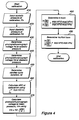
- the step of calibrating the photoplethysmograph outputs to the patient 9, shown in Figure 3, block 310 is shown in expanded detail in Figure 4.
- the first two steps, shown in block 410 and block 420 are the determination and entering of the systolic and diastolic blood pressures, P s and P d , respectively, at calibration into the computer 24.
- these blood pressures are determined by an auxiliary blood pressure instrument 20, preferably an accurate blood pressure cuff having direct inputs to the computer 24 via the instrument bus 28.
- the next two steps, shown in blocks 430 and 440 of Figure 4 are the determination of the photoplethysmograph voltages, V s and V d , from the receiver 18 output at the calibration systolic and diastolic blood pressures, respectively. These photoplethysmograph voltages are readily determined since they are the minimum and maximum output signals, respectively, from the A/D converter 23.
- the duration of the cardiac cycle, t d is determined from the output of the A/D converter 23. This is also readily accomplished by using a counter to determine the time between the diastolic voltages, times t0 and t1 of Figure 2.
- the preferred method requires that the area between the diastolic voltage V d and waveform function f(t), or ARC, be determined.
- ARC is easily performed using a digital computer since the output of the A/D converter 23 is a series of digital representations of the photoplethysmograph signals over time.
- Using the Simpson approximation to determine the integral is particularly expedient because the digital magnitudes can be multiplied by the sampling time between readings, then summed, to arrive at ARC. While ARC is preferably determined using integral equations, other methods of determining it are also acceptable.
- V m V d - (ARC/t d ); where all terms are as previously given.
- the patient's arterial blood pressures can be determined only from the photoplethysmograph output.
- the computer 24 monitors the photoplethysmograph outputs to determine, at the time of measurement, the systolic voltage V s , the diastolic voltage V d , the duration of the cardiac cycle t d and the ARC, as shown in blocks 510, 520, 530 and 540, of Figure 5 respectively.
- systolic and diastolic blood pressures are then available for output to medical personnel as shown in block 640, in a variety of way such as by digital or analog readouts, chart recorders, voice synthesis, or as in the present embodiment on a display monitor 30. If another set of measurements is desired then decision block 650 causes the flow shown in Figures 5 and 6 to be repeated.
- the preferred embodiment described above is useful, can be readily implemented on a digital computer, and provides accurate and rapid measurements of arterial blood pressures non-invasively and in a manner suitable for continuous measurements.
- the preferred method leads to inaccuracies because of time variations in V inf , the equivalent receiver voltage at infinite pressure.
- V inf in the preferred method was part of the ratio V0/V inf determined during calibration and presumed constant.
- the preferred embodiment can be modified to compensate for changes in V inf but at the expense of additional computation difficulty and time.
- the data gathering steps depicted in Figure 5 remain the same.
- the flow diagram of Figure 6 is modified to the procedural steps shown in Figure 8.
- V inf exp ⁇ ln(V s ) - [exp(-kP p )]lnV d ]/[1-exp(-kP p )] ⁇
- V s and V d are also the values at the time of measurement.
- This new V inf is then used in the equation of block 830, along with the previously stored value of V0, to determine the diastolic pressure P d .
- This alternative embodiment reduces the effects of changes in V inf .
- the calculation of the systolic pressure P s , shown in Block 840, and the output of the systolic and diastolic pressures, P d and P s , respectively, as shown in block 850 are performed in the same manner as they were in blocks 630 and 640, respectively, of Figure 6.
- the decision block 860 operates in the same manner as the decision block 650 in Figure 6.
- the apparatus for practicing the present invention uses a modified pulse oximeter-type photoplethysmograph 4 having numerous user controls, such as receiver 18 gain and light source 8 current settings. It outputs an analog voltage representation of the photodiode output to an analog-to-digital converter A/D 23 which digitizes the receiver 18 output and applies it to an IBM-AT type personal computer 24 under the control of software stored in a hard-disk drive.
- the display 30 output is on a computer monitor.
- the required auxiliary blood pressure instrument 20 readings are input by keyboard when directed by software programmed prompts.
- the separate photoplethysmograph 4, A/D converter 23, and computer 24 will probably be replace by similar structures within a single chassis and calibration data will be automatically inputted by an automatic blood pressure cuff.
Landscapes
- Health & Medical Sciences (AREA)
- Life Sciences & Earth Sciences (AREA)
- Cardiology (AREA)
- Engineering & Computer Science (AREA)
- Heart & Thoracic Surgery (AREA)
- Physiology (AREA)
- Biophysics (AREA)
- Pathology (AREA)
- Veterinary Medicine (AREA)
- Biomedical Technology (AREA)
- Physics & Mathematics (AREA)
- Medical Informatics (AREA)
- Molecular Biology (AREA)
- Surgery (AREA)
- Animal Behavior & Ethology (AREA)
- General Health & Medical Sciences (AREA)
- Public Health (AREA)
- Vascular Medicine (AREA)
- Measuring Pulse, Heart Rate, Blood Pressure Or Blood Flow (AREA)
Abstract
Claims (10)
- Procédé de détermination des pressions sanguines artérielles systolique et diastolique utilisant un photopléthysmographe incluant un détenteur photopléthysmographique (8) dans lequel de la lumière passe travers une artère (12) d'un patient (9), le photopléthysmographe produisant un signal de sortie électrique ayant une relation prédéterminée par rapport au volume sanguin dans l'artère (12), le procédé comprenant les étapes suivantes :
étalonner le photopléthysmographe (4) au cours d'une période d'étalonnage (310) en déterminant la pression sanguine artérielle réelle du patient (9) par des moyens (20) autres que le photopléthysmographe (4), caractérisé par la détermination de la valeur d'une première constante artérielle (k) dans une relation prédéterminée
analyser et collecter les données en provenance du signal de sortie du photopléthysmographe pendant une durée de mesure pour déterminer les pressions sanguines artérielles systolique et diastolique correspondant au signal de sortie en accord avec la relation prédéterminée définissant la pression sanguine artérielle (P) en fonction du volume sanguin artériel (Ψ), tel qu'indiqué par la signal de sortie du photopléthysmographe, de la première constante artérielle (k) telle que déterminée à l'étape précédente, et de la constante de conversion (Ψinf) correspondant au volume sanguin artériel à pression infinie. - Procédé selon la revendication 1, dans lequel la constante de conversion (Ψinf) correspondant au volume sanguin artériel à pression infinie est déterminée en examinant la relation entre le volume sanguin artériel et la pression sanguine artérielle, et en déterminant alors le volume sanguin artériel à pression infinie en tant que la valeur asymptotique du volume sanguin artériel dans ladite relation.
- Procédé selon la revendication 1, comprenant en outre les étapes consistant à déterminée à partie du signal de sortie du photopléthysmographe une valeur td correspondant à la durée du cycle cardiaque pendant la durée de mesure, une valeur S correspondant à la pression systolique pendant la période de mesure, une valeur D correspondant à la pression diastolique pendant la période de mesure, et une valeur ARC correspondant à l'intégrale en fonction du temps de la différence entre le signal de sortie du photopléthysmographe dans la période de mesure et une valeur du signal de sortie du photopléthysmographe correspondant à la pression diastolique.
- Procédé selon la revendication 1, dans lequel l'étape d'étalonnage du photopléthysmographe pendant une période d'étalonnage comprend les étapes suivantes :
déterminer les pressions sanguines artérielles réelles systolique et diastolique et la pression moyenne, Ps, Pd et Pm, respectivement, pendant la période d'étalonnage par des moyens autres que la photopléthysmographe ;
déterminer les valeurs Vd et Vs du signal de sortie du photopléthysmographe correspondant aux pressions artérielles respectives diastolique et systolique pendant la période d'étalonnge ;
déterminer la valeur Vm correspondant à la moyenne du signal de sortie du photopléthysmographe pendant la période d'étalonnage ; et
calculer la première constante artérielle k par la relation :
- Procédé selon la revendication 4, dans lequel l'étape de détermination d'une valeur Vm correspondant à la moyenne du signal de sortie du photopléthysmographe pendant la période d'étalonnage est réalisée en calculant Vm par la relation :

- Procédé selon la revendication 1, comprenant en autre l'étape consistant à déterminer à partir du signal de sortie du photopléthysmographe une valeur X correspondant à la pression artérielle impulsionnelle pendant la période de mesure par les étapes suivantes :
déterminer des valeurs Vd et Vs du signal de sortie du photopléthysmographe correspondant aux pressions artérielles respectives diastolique et systolique pendant la période d'étalonnage ;
déterminer une valeur Vm correspondant à la moyenne du signal de sortie due photopléthysmographe pendant la période d'étalonnage ; et
calculer la valeur X correspondant à la pression artérielle impulsionnelle pendant la période de mesure à partir de la relation :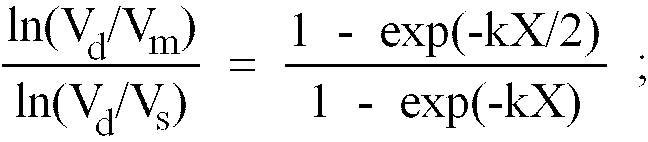
- Procédé selon la revendication 6, dans lequel l'étape d'étalonnage du photopléthysmographe pendant la période d'étalonnage comprend en cutre les étapes suivantes :
déterminer les pressions sanguines artérielles réelles systolique et diastolique Ps et Pd, respectivement, pendant la période d'étalonnage par des moyens autres que le photopléthysmographe ;
calculer le rapport V₀/Vinf pendant la période d'étalonnage par la relation :
- Procédé selon la revendication 7, comprenant en autre l'étape consistant à déterminer à partir du signal de sortie du photopléthysmographe une valeur D correspondant à la pression diastolique pendant la période de mesure en calculant D par la relation :

- Procédé selon la revendication 6, dans lequel l'étape d'étalonnage du photopléthysmographe pendant la période d'étalonnage comprend en autre les étapes suivantes :
déterminer Vinf au moment de la période d'étalonnage par la relation :

- Procédé selon la revendication 9, comprenant en outre l'étape consistant à déterminer à partir du signal de sortie du photopléthysmographe une valeur D correspondant à la pression diastolique pendant la période de mesure en calculant D par la relation :

Applications Claiming Priority (5)
| Application Number | Priority Date | Filing Date | Title |
|---|---|---|---|
| US579159 | 1984-02-10 | ||
| US57915990A | 1990-09-06 | 1990-09-06 | |
| US07/656,021 US5140990A (en) | 1990-09-06 | 1991-02-15 | Method of measuring blood pressure with a photoplethysmograph |
| PCT/US1991/006914 WO1992003967A2 (fr) | 1990-09-06 | 1991-09-06 | Procede de mesure de la pression sanguine a l'aide d'un photoplethysmographe |
| US656021 | 2000-09-06 |
Publications (2)
| Publication Number | Publication Date |
|---|---|
| EP0498885A1 EP0498885A1 (fr) | 1992-08-19 |
| EP0498885B1 true EP0498885B1 (fr) | 1996-05-22 |
Family
ID=27077687
Family Applications (1)
| Application Number | Title | Priority Date | Filing Date |
|---|---|---|---|
| EP91918602A Expired - Lifetime EP0498885B1 (fr) | 1990-09-06 | 1991-09-06 | Procede de mesure de la pression sanguine a l'aide d'un photoplethysmographe |
Country Status (5)
| Country | Link |
|---|---|
| US (1) | US5140990A (fr) |
| EP (1) | EP0498885B1 (fr) |
| CA (1) | CA2073019A1 (fr) |
| DE (1) | DE69119741T2 (fr) |
| WO (1) | WO1992003967A2 (fr) |
Cited By (1)
| Publication number | Priority date | Publication date | Assignee | Title |
|---|---|---|---|---|
| WO2019091517A1 (fr) | 2017-11-13 | 2019-05-16 | Technische Universität Dresden | Procédé de détermination de la pression artérielle en tenant compte d'un paramètre physiologique |
Families Citing this family (119)
| Publication number | Priority date | Publication date | Assignee | Title |
|---|---|---|---|---|
| US5423322A (en) * | 1988-12-29 | 1995-06-13 | Medical Physics, Inc. | Total compliance method and apparatus for noninvasive arterial blood pressure measurement |
| US5269310A (en) * | 1990-09-06 | 1993-12-14 | Spacelabs Medical, Inc. | Method of measuring blood pressure with a plethysmograph |
| US5485848A (en) * | 1991-01-31 | 1996-01-23 | Jackson; Sandra R. | Portable blood pressure measuring device and method of measuring blood pressure |
| DE4226972A1 (de) * | 1992-08-14 | 1994-02-17 | Vladimir Dr Blazek | Verfahren und Meßvorrichtung zur nichtinvasiven Bestimmung der venösen und arteriellen Blutdruckwerte |
| FR2726457B1 (fr) * | 1994-11-08 | 1998-08-28 | Lavoisier Pierre | Procede de mesure concernant la rigidite d'un penis et dispositif pour la mise en oeuvre de ce procede |
| JP3666987B2 (ja) * | 1996-05-02 | 2005-06-29 | コーリンメディカルテクノロジー株式会社 | 血圧監視装置 |
| US5752920A (en) * | 1996-08-01 | 1998-05-19 | Colin Corporation | Blood pressure monitor apparatus |
| US5865755A (en) * | 1996-10-11 | 1999-02-02 | Dxtek, Inc. | Method and apparatus for non-invasive, cuffless, continuous blood pressure determination |
| US5991654A (en) * | 1997-06-06 | 1999-11-23 | Kci New Technologies, Inc. | Apparatus and method for detecting deep vein thrombosis |
| JP2000157499A (ja) * | 1998-11-27 | 2000-06-13 | Nippon Colin Co Ltd | 血圧監視装置 |
| US6331162B1 (en) | 1999-02-01 | 2001-12-18 | Gary F. Mitchell | Pulse wave velocity measuring device |
| GB2356252B (en) * | 1999-11-12 | 2004-02-25 | Micro Medical Ltd | Apparatus for measuring the shape of an arterial pressure pulse in a person |
| US6616613B1 (en) | 2000-04-27 | 2003-09-09 | Vitalsines International, Inc. | Physiological signal monitoring system |
| US6533729B1 (en) | 2000-05-10 | 2003-03-18 | Motorola Inc. | Optical noninvasive blood pressure sensor and method |
| US6475153B1 (en) | 2000-05-10 | 2002-11-05 | Motorola Inc. | Method for obtaining blood pressure data from optical sensor |
| JP2002172095A (ja) * | 2000-12-06 | 2002-06-18 | K & S:Kk | 脈波測定装置 |
| US7473231B2 (en) * | 2002-06-25 | 2009-01-06 | Francis Y. Falck | Method and apparatus for examining an eye |
| CA2505136C (fr) * | 2002-11-06 | 2013-07-23 | Itamar Medical Ltd. | Procede et dispositif d'utilisation de sondes servant a effectuer la detection non invasive d'etats pathologiques corporels |
| US20050148882A1 (en) * | 2004-01-06 | 2005-07-07 | Triage Wireless, Incc. | Vital signs monitor used for conditioning a patient's response |
| US20060142648A1 (en) * | 2003-01-07 | 2006-06-29 | Triage Data Networks | Wireless, internet-based, medical diagnostic system |
| US7435214B2 (en) * | 2004-01-29 | 2008-10-14 | Cannuflow, Inc. | Atraumatic arthroscopic instrument sheath |
| US20050216199A1 (en) * | 2004-03-26 | 2005-09-29 | Triage Data Networks | Cuffless blood-pressure monitor and accompanying web services interface |
| US20050228300A1 (en) * | 2004-04-07 | 2005-10-13 | Triage Data Networks | Cuffless blood-pressure monitor and accompanying wireless mobile device |
| US20050261598A1 (en) * | 2004-04-07 | 2005-11-24 | Triage Wireless, Inc. | Patch sensor system for measuring vital signs |
| US20050228297A1 (en) * | 2004-04-07 | 2005-10-13 | Banet Matthew J | Wrist-worn System for Measuring Blood Pressure |
| US20050228244A1 (en) * | 2004-04-07 | 2005-10-13 | Triage Wireless, Inc. | Small-scale, vital-signs monitoring device, system and method |
| US7004907B2 (en) * | 2004-04-07 | 2006-02-28 | Triage Wireless, Inc. | Blood-pressure monitoring device featuring a calibration-based analysis |
| US20060009698A1 (en) * | 2004-04-07 | 2006-01-12 | Triage Wireless, Inc. | Hand-held monitor for measuring vital signs |
| US7179228B2 (en) * | 2004-04-07 | 2007-02-20 | Triage Wireless, Inc. | Cuffless system for measuring blood pressure |
| US7238159B2 (en) * | 2004-04-07 | 2007-07-03 | Triage Wireless, Inc. | Device, system and method for monitoring vital signs |
| US20060009697A1 (en) * | 2004-04-07 | 2006-01-12 | Triage Wireless, Inc. | Wireless, internet-based system for measuring vital signs from a plurality of patients in a hospital or medical clinic |
| US20060047447A1 (en) * | 2004-08-24 | 2006-03-02 | Impact Sports Technologies, Inc. | System, method and device for monitoring an athlete |
| US9820658B2 (en) | 2006-06-30 | 2017-11-21 | Bao Q. Tran | Systems and methods for providing interoperability among healthcare devices |
| US7502498B2 (en) | 2004-09-10 | 2009-03-10 | Available For Licensing | Patient monitoring apparatus |
| US7887492B1 (en) | 2004-09-28 | 2011-02-15 | Impact Sports Technologies, Inc. | Monitoring device, method and system |
| US20060253010A1 (en) * | 2004-09-28 | 2006-11-09 | Donald Brady | Monitoring device, method and system |
| US20060079794A1 (en) * | 2004-09-28 | 2006-04-13 | Impact Sports Technologies, Inc. | Monitoring device, method and system |
| US7544168B2 (en) * | 2004-09-30 | 2009-06-09 | Jerusalem College Of Technology | Measuring systolic blood pressure by photoplethysmography |
| US20060084878A1 (en) * | 2004-10-18 | 2006-04-20 | Triage Wireless, Inc. | Personal computer-based vital signs monitor |
| US7658716B2 (en) * | 2004-12-07 | 2010-02-09 | Triage Wireless, Inc. | Vital signs monitor using an optical ear-based module |
| US7733224B2 (en) | 2006-06-30 | 2010-06-08 | Bao Tran | Mesh network personal emergency response appliance |
| US7420472B2 (en) | 2005-10-16 | 2008-09-02 | Bao Tran | Patient monitoring apparatus |
| US20070142715A1 (en) * | 2005-12-20 | 2007-06-21 | Triage Wireless, Inc. | Chest strap for measuring vital signs |
| US20070185393A1 (en) * | 2006-02-03 | 2007-08-09 | Triage Wireless, Inc. | System for measuring vital signs using an optical module featuring a green light source |
| RU2309668C1 (ru) * | 2006-02-20 | 2007-11-10 | Александр Сергеевич Парфенов | Способ неинвазивного определения функции эндотелия и устройство для его осуществления |
| US7558622B2 (en) | 2006-05-24 | 2009-07-07 | Bao Tran | Mesh network stroke monitoring appliance |
| US9060683B2 (en) | 2006-05-12 | 2015-06-23 | Bao Tran | Mobile wireless appliance |
| US8968195B2 (en) | 2006-05-12 | 2015-03-03 | Bao Tran | Health monitoring appliance |
| US7539532B2 (en) | 2006-05-12 | 2009-05-26 | Bao Tran | Cuffless blood pressure monitoring appliance |
| US8500636B2 (en) | 2006-05-12 | 2013-08-06 | Bao Tran | Health monitoring appliance |
| US8684922B2 (en) | 2006-05-12 | 2014-04-01 | Bao Tran | Health monitoring system |
| US8323189B2 (en) | 2006-05-12 | 2012-12-04 | Bao Tran | Health monitoring appliance |
| US7539533B2 (en) | 2006-05-16 | 2009-05-26 | Bao Tran | Mesh network monitoring appliance |
| US8684900B2 (en) | 2006-05-16 | 2014-04-01 | Bao Tran | Health monitoring appliance |
| US7993275B2 (en) * | 2006-05-25 | 2011-08-09 | Sotera Wireless, Inc. | Bilateral device, system and method for monitoring vital signs |
| US9149192B2 (en) * | 2006-05-26 | 2015-10-06 | Sotera Wireless, Inc. | System for measuring vital signs using bilateral pulse transit time |
| US8442607B2 (en) * | 2006-09-07 | 2013-05-14 | Sotera Wireless, Inc. | Hand-held vital signs monitor |
| US20080082004A1 (en) * | 2006-09-08 | 2008-04-03 | Triage Wireless, Inc. | Blood pressure monitor |
| US8449469B2 (en) * | 2006-11-10 | 2013-05-28 | Sotera Wireless, Inc. | Two-part patch sensor for monitoring vital signs |
| US20080221399A1 (en) * | 2007-03-05 | 2008-09-11 | Triage Wireless, Inc. | Monitor for measuring vital signs and rendering video images |
| US20080221461A1 (en) * | 2007-03-05 | 2008-09-11 | Triage Wireless, Inc. | Vital sign monitor for cufflessly measuring blood pressure without using an external calibration |
| US7922664B2 (en) * | 2007-04-05 | 2011-04-12 | Coherence Llc | Method and system for improving physiologic status and health via assessment of the dynamic respiratory arterial pressure wave using plethysmographic technique |
| US7884727B2 (en) | 2007-05-24 | 2011-02-08 | Bao Tran | Wireless occupancy and day-light sensing |
| US11607152B2 (en) | 2007-06-12 | 2023-03-21 | Sotera Wireless, Inc. | Optical sensors for use in vital sign monitoring |
| US12245852B2 (en) | 2007-06-12 | 2025-03-11 | Sotera Wireless, Inc. | Optical sensors for use in vital sign monitoring |
| US11330988B2 (en) | 2007-06-12 | 2022-05-17 | Sotera Wireless, Inc. | Body-worn system for measuring continuous non-invasive blood pressure (cNIBP) |
| US8602997B2 (en) * | 2007-06-12 | 2013-12-10 | Sotera Wireless, Inc. | Body-worn system for measuring continuous non-invasive blood pressure (cNIBP) |
| WO2008154643A1 (fr) * | 2007-06-12 | 2008-12-18 | Triage Wireless, Inc. | Moniteur de signaux vitaux pour mesure de tension artérielle en utilisant des formes d'onde optique, électrique et de tension |
| US8398556B2 (en) * | 2008-06-30 | 2013-03-19 | Covidien Lp | Systems and methods for non-invasive continuous blood pressure determination |
| US20090326386A1 (en) * | 2008-06-30 | 2009-12-31 | Nellcor Puritan Bennett Ireland | Systems and Methods for Non-Invasive Blood Pressure Monitoring |
| US20100081946A1 (en) * | 2008-09-26 | 2010-04-01 | Qualcomm Incorporated | Method and apparatus for non-invasive cuff-less blood pressure estimation using pulse arrival time and heart rate with adaptive calibration |
| ES2336997B1 (es) | 2008-10-16 | 2011-06-13 | Sabirmedical,S.L. | Sistema y aparato para la medicion no invasiva de la presion arterial. |
| US8057400B2 (en) | 2009-05-12 | 2011-11-15 | Angiologix, Inc. | System and method of measuring changes in arterial volume of a limb segment |
| US10555676B2 (en) | 2009-05-20 | 2020-02-11 | Sotera Wireless, Inc. | Method for generating alarms/alerts based on a patient's posture and vital signs |
| US11896350B2 (en) | 2009-05-20 | 2024-02-13 | Sotera Wireless, Inc. | Cable system for generating signals for detecting motion and measuring vital signs |
| US8475370B2 (en) * | 2009-05-20 | 2013-07-02 | Sotera Wireless, Inc. | Method for measuring patient motion, activity level, and posture along with PTT-based blood pressure |
| US9775529B2 (en) | 2009-06-17 | 2017-10-03 | Sotera Wireless, Inc. | Body-worn pulse oximeter |
| US12121364B2 (en) | 2009-09-14 | 2024-10-22 | Sotera Wireless, Inc. | Body-worn monitor for measuring respiration rate |
| US11253169B2 (en) | 2009-09-14 | 2022-02-22 | Sotera Wireless, Inc. | Body-worn monitor for measuring respiration rate |
| US8740807B2 (en) * | 2009-09-14 | 2014-06-03 | Sotera Wireless, Inc. | Body-worn monitor for measuring respiration rate |
| US8527038B2 (en) * | 2009-09-15 | 2013-09-03 | Sotera Wireless, Inc. | Body-worn vital sign monitor |
| US12156743B2 (en) | 2009-09-15 | 2024-12-03 | Sotera Wireless, Inc. | Body-worn vital sign monitor |
| US10420476B2 (en) | 2009-09-15 | 2019-09-24 | Sotera Wireless, Inc. | Body-worn vital sign monitor |
| US20110066044A1 (en) | 2009-09-15 | 2011-03-17 | Jim Moon | Body-worn vital sign monitor |
| US8364250B2 (en) * | 2009-09-15 | 2013-01-29 | Sotera Wireless, Inc. | Body-worn vital sign monitor |
| US8321004B2 (en) * | 2009-09-15 | 2012-11-27 | Sotera Wireless, Inc. | Body-worn vital sign monitor |
| US10806351B2 (en) * | 2009-09-15 | 2020-10-20 | Sotera Wireless, Inc. | Body-worn vital sign monitor |
| US20110224500A1 (en) * | 2010-03-10 | 2011-09-15 | Sotera Wireless, Inc. | Body-worn vital sign monitor |
| US9339209B2 (en) | 2010-04-19 | 2016-05-17 | Sotera Wireless, Inc. | Body-worn monitor for measuring respiratory rate |
| US8979765B2 (en) | 2010-04-19 | 2015-03-17 | Sotera Wireless, Inc. | Body-worn monitor for measuring respiratory rate |
| US9173594B2 (en) | 2010-04-19 | 2015-11-03 | Sotera Wireless, Inc. | Body-worn monitor for measuring respiratory rate |
| US8747330B2 (en) | 2010-04-19 | 2014-06-10 | Sotera Wireless, Inc. | Body-worn monitor for measuring respiratory rate |
| US8888700B2 (en) | 2010-04-19 | 2014-11-18 | Sotera Wireless, Inc. | Body-worn monitor for measuring respiratory rate |
| US9173593B2 (en) | 2010-04-19 | 2015-11-03 | Sotera Wireless, Inc. | Body-worn monitor for measuring respiratory rate |
| US10722131B2 (en) | 2010-12-28 | 2020-07-28 | Sotera Wireless, Inc. | Body-worn system for continuous, noninvasive measurement of cardiac output, stroke volume, cardiac power, and blood pressure |
| US8761853B2 (en) | 2011-01-20 | 2014-06-24 | Nitto Denko Corporation | Devices and methods for non-invasive optical physiological measurements |
| EP2675346B1 (fr) | 2011-02-18 | 2024-04-10 | Sotera Wireless, Inc. | Capteur optique pour la mesure de propriétés physiologiques |
| US9439574B2 (en) | 2011-02-18 | 2016-09-13 | Sotera Wireless, Inc. | Modular wrist-worn processor for patient monitoring |
| GB201111138D0 (en) * | 2011-06-30 | 2011-08-17 | Leman Micro Devices Uk Ltd | Personal health data collection |
| WO2013076722A1 (fr) | 2011-11-24 | 2013-05-30 | Itamar Medical Ltd. | Appareil de surveillance des ondes du pouls artériel pour le diagnostic de diverses affections médicales |
| EP2928360B1 (fr) | 2012-12-04 | 2017-01-11 | Koninklijke Philips N.V. | Dispositif et procédé pour obtenir des informations de signes vitaux d'un être vivant |
| US9865176B2 (en) | 2012-12-07 | 2018-01-09 | Koninklijke Philips N.V. | Health monitoring system |
| CN105307568B (zh) | 2013-02-13 | 2018-11-16 | 莱曼微设备有限公司 | 非侵入式血液分析 |
| US20190142286A1 (en) * | 2014-03-31 | 2019-05-16 | Sensogram Technologies, Inc. | Photoplethysmographic wearable blood pressure monitoring system and methods |
| US10117586B1 (en) | 2014-03-31 | 2018-11-06 | Sensogram Technologies, Inc. | Continuous non-invasive wearable blood pressure monitoring system |
| EP3212070B1 (fr) | 2014-10-27 | 2020-02-05 | Vitalsines International Inc. | Système et procédé de surveillance de la vitesse d'ondes de pouls aortique et de la pression artérielle |
| KR101656369B1 (ko) | 2015-04-20 | 2016-09-09 | 연세대학교 산학협력단 | Ppg를 이용한 사지 혈관 진단 및 정확도 상승 피드백 시스템 및 방법 |
| CN111904384B (zh) * | 2015-04-27 | 2024-09-10 | 苹果公司 | 用于ppg信号优化和环境光缓解的动态可配置光阑 |
| US11864874B2 (en) | 2015-06-18 | 2024-01-09 | CSEM Centre Suisse d'Electronique et de Microtechnique SA—Recherche et Développement | Method, apparatus and computer program for determining a blood pressure value |
| US10856743B2 (en) * | 2015-08-28 | 2020-12-08 | Oslermd, Inc. | Methods and apparatuses for measuring multiple vital signs based on arterial pressure waveforms |
| KR102487982B1 (ko) * | 2015-10-02 | 2023-01-11 | 삼성전자주식회사 | 혈압 측정 장치, 및 광원 선택 프로세스를 포함하는 혈압 측정 장치 |
| WO2017086294A1 (fr) * | 2015-11-17 | 2017-05-26 | 国立大学法人東北大学 | Dispositif d'estimation de la pression artérielle, dispositif de traitement d'informations, procédé d'estimation de la pression artérielle et programme d'estimation de la pression artérielle |
| US10694995B2 (en) | 2017-12-05 | 2020-06-30 | Renegade Optophysics, Llc | Diagnostic eye goggle system |
| US12507899B2 (en) * | 2019-12-06 | 2025-12-30 | Savan Patel | Systems and methods for vascular disease prediction, indication, or diagnosis |
| EP3928690B1 (fr) * | 2020-06-26 | 2024-09-11 | Ectosense NV | Procédé et appareil d'évaluation du tonus artériel périphérique |
| US20220328178A1 (en) * | 2021-04-08 | 2022-10-13 | Guy P. Curtis | System and method for correlating pulse oximetry waveform signals with blood pressure |
| CN113706984B (zh) * | 2021-08-06 | 2022-07-12 | 西安交通大学 | 一种血压和反射式光电容积波同步模拟定标装置及方法 |
| CN113670516B (zh) * | 2021-08-12 | 2024-02-09 | 之江实验室 | 基于光体积变化描记成像的按压位置定位和压力测量方法 |
| US20230157555A1 (en) * | 2021-11-25 | 2023-05-25 | Shenzhen GOODIX Technology Co., Ltd. | Blood-volume-based cuff-less non-invasive blood pressure monitoring |
Citations (1)
| Publication number | Priority date | Publication date | Assignee | Title |
|---|---|---|---|---|
| US4418700A (en) * | 1981-03-11 | 1983-12-06 | Sylvia Warner | Method and apparatus for measurement of heart-related parameters |
Family Cites Families (11)
| Publication number | Priority date | Publication date | Assignee | Title |
|---|---|---|---|---|
| US4030485A (en) * | 1974-11-12 | 1977-06-21 | Glenfield Warner | Method and apparatus for continuously monitoring systolic blood pressure |
| US4105021A (en) * | 1976-08-13 | 1978-08-08 | Joseph H. Allen | Method and arrangement for measuring blood pressure |
| US4343314A (en) * | 1980-08-11 | 1982-08-10 | Bohumir Sramek | Non-invasive real time blood pressure measurement system |
| US4437469A (en) * | 1980-09-29 | 1984-03-20 | Rush-Presbyterian-St. Luke's Medical Center | System for determining characteristics of blood flow |
| NL8105381A (nl) * | 1981-11-27 | 1983-06-16 | Tno | Werkwijze en inrichting voor het corrigeren van de manchetdruk bij het meten van de bloeddruk in een lichaamsdeel met behulp van een plethysmograaf. |
| JPS59181129A (ja) * | 1983-03-31 | 1984-10-15 | 株式会社エー・アンド・ディ | 血圧測定装置 |
| US4718428A (en) * | 1984-02-17 | 1988-01-12 | Cortronic Corporation | Method for determining diastolic arterial blood pressure in a subject |
| EP0160994A3 (fr) * | 1984-05-10 | 1987-02-04 | Warner, Sylvia | Appareil de surveillance de paramètres relatifs à la circulation sanguine |
| US4834107A (en) * | 1984-05-10 | 1989-05-30 | Sylvia Warner | Heart-related parameters monitoring apparatus |
| US4819646A (en) * | 1986-08-18 | 1989-04-11 | Physio-Control Corporation | Feedback-controlled method and apparatus for processing signals used in oximetry |
| US4846189A (en) * | 1987-06-29 | 1989-07-11 | Shuxing Sun | Noncontactive arterial blood pressure monitor and measuring method |
-
1991
- 1991-02-15 US US07/656,021 patent/US5140990A/en not_active Expired - Fee Related
- 1991-09-06 DE DE69119741T patent/DE69119741T2/de not_active Expired - Fee Related
- 1991-09-06 EP EP91918602A patent/EP0498885B1/fr not_active Expired - Lifetime
- 1991-09-06 CA CA002073019A patent/CA2073019A1/fr not_active Abandoned
- 1991-09-06 WO PCT/US1991/006914 patent/WO1992003967A2/fr not_active Ceased
Patent Citations (1)
| Publication number | Priority date | Publication date | Assignee | Title |
|---|---|---|---|---|
| US4418700A (en) * | 1981-03-11 | 1983-12-06 | Sylvia Warner | Method and apparatus for measurement of heart-related parameters |
Cited By (1)
| Publication number | Priority date | Publication date | Assignee | Title |
|---|---|---|---|---|
| WO2019091517A1 (fr) | 2017-11-13 | 2019-05-16 | Technische Universität Dresden | Procédé de détermination de la pression artérielle en tenant compte d'un paramètre physiologique |
Also Published As
| Publication number | Publication date |
|---|---|
| WO1992003967A3 (fr) | 1992-04-30 |
| CA2073019A1 (fr) | 1992-03-07 |
| DE69119741T2 (de) | 1996-10-02 |
| DE69119741D1 (de) | 1996-06-27 |
| EP0498885A1 (fr) | 1992-08-19 |
| WO1992003967A2 (fr) | 1992-03-19 |
| US5140990A (en) | 1992-08-25 |
Similar Documents
| Publication | Publication Date | Title |
|---|---|---|
| EP0498885B1 (fr) | Procede de mesure de la pression sanguine a l'aide d'un photoplethysmographe | |
| US5269310A (en) | Method of measuring blood pressure with a plethysmograph | |
| US6022320A (en) | Blood pressure monitor apparatus | |
| US7785263B2 (en) | Pressure-based system and method for determining cardiac stroke volume | |
| US5241966A (en) | Method and apparatus for measuring cardiac output | |
| JP3710823B2 (ja) | 心拍出量の測定のための改良された方法及び装置 | |
| US5865758A (en) | System for obtaining hemodynamic information | |
| US6186954B1 (en) | Blood-pressure monitoring apparatus | |
| EP0997103B1 (fr) | Dispositif de la mesure non-invasive et continue de la pression sanguine | |
| US4418700A (en) | Method and apparatus for measurement of heart-related parameters | |
| KR101286402B1 (ko) | 휴대용 진단 기구 | |
| US4869262A (en) | Device for displaying blood pressure | |
| US11406273B2 (en) | Continuous blood pressure measurement | |
| EP2074942A1 (fr) | Procédé et appareil pour la surveillance continue non invasive et non obstructive de la tension artérielle | |
| EP0615723A1 (fr) | Méthode et dispositif pour mesurer le débit sanguin | |
| JPH0614891A (ja) | 連続無侵襲血圧モニター方法及びその装置 | |
| CN102186411A (zh) | 用于非创伤的测量血压的系统和装置 | |
| JP3107630B2 (ja) | パルスオキシメータ | |
| JPH07327964A (ja) | 酸素飽和度測定装置および血中吸光物質濃度測定装置 | |
| US20200253564A1 (en) | Continuous Blood Pressure Measurement | |
| EP0181067B1 (fr) | Dispositif indicateur de valeurs de la pression sanguine | |
| WO1992006633A1 (fr) | Procede et appareil de mesure du debit cardiaque | |
| JPH05269116A (ja) | 改良された動脈血のモニター装置 | |
| EP1150604B1 (fr) | Procede et dispositif d'analyse en continu d'une activite cardio-vasculaire d'un sujet | |
| JPH06277202A (ja) | 診断装置 |
Legal Events
| Date | Code | Title | Description |
|---|---|---|---|
| PUAI | Public reference made under article 153(3) epc to a published international application that has entered the european phase |
Free format text: ORIGINAL CODE: 0009012 |
|
| 17P | Request for examination filed |
Effective date: 19920506 |
|
| AK | Designated contracting states |
Kind code of ref document: A1 Designated state(s): CH DE FR GB IT LI |
|
| 17Q | First examination report despatched |
Effective date: 19940725 |
|
| GRAH | Despatch of communication of intention to grant a patent |
Free format text: ORIGINAL CODE: EPIDOS IGRA |
|
| GRAA | (expected) grant |
Free format text: ORIGINAL CODE: 0009210 |
|
| RAP1 | Party data changed (applicant data changed or rights of an application transferred) |
Owner name: SPACELABS MEDICAL, INC. |
|
| AK | Designated contracting states |
Kind code of ref document: B1 Designated state(s): CH DE FR GB IT LI |
|
| PG25 | Lapsed in a contracting state [announced via postgrant information from national office to epo] |
Ref country code: LI Effective date: 19960522 Ref country code: CH Effective date: 19960522 |
|
| ITF | It: translation for a ep patent filed | ||
| REF | Corresponds to: |
Ref document number: 69119741 Country of ref document: DE Date of ref document: 19960627 |
|
| ET | Fr: translation filed | ||
| PG25 | Lapsed in a contracting state [announced via postgrant information from national office to epo] |
Ref country code: GB Effective date: 19960906 |
|
| REG | Reference to a national code |
Ref country code: CH Ref legal event code: PL |
|
| PLBE | No opposition filed within time limit |
Free format text: ORIGINAL CODE: 0009261 |
|
| STAA | Information on the status of an ep patent application or granted ep patent |
Free format text: STATUS: NO OPPOSITION FILED WITHIN TIME LIMIT |
|
| GBPC | Gb: european patent ceased through non-payment of renewal fee |
Effective date: 19960906 |
|
| 26N | No opposition filed | ||
| PG25 | Lapsed in a contracting state [announced via postgrant information from national office to epo] |
Ref country code: DE Effective date: 19970603 |
|
| PG25 | Lapsed in a contracting state [announced via postgrant information from national office to epo] |
Ref country code: FR Effective date: 19970630 |
|
| REG | Reference to a national code |
Ref country code: FR Ref legal event code: ST |
|
| REG | Reference to a national code |
Ref country code: FR Ref legal event code: ST |
|
| PG25 | Lapsed in a contracting state [announced via postgrant information from national office to epo] |
Ref country code: IT Free format text: LAPSE BECAUSE OF NON-PAYMENT OF DUE FEES Effective date: 20050906 |