EP0498902A1 - Interféromètre à fibre optique du type sagnac avec modulation digitale de phase pour la mesure de vitesse de rotation - Google Patents
Interféromètre à fibre optique du type sagnac avec modulation digitale de phase pour la mesure de vitesse de rotation Download PDFInfo
- Publication number
- EP0498902A1 EP0498902A1 EP91101872A EP91101872A EP0498902A1 EP 0498902 A1 EP0498902 A1 EP 0498902A1 EP 91101872 A EP91101872 A EP 91101872A EP 91101872 A EP91101872 A EP 91101872A EP 0498902 A1 EP0498902 A1 EP 0498902A1
- Authority
- EP
- European Patent Office
- Prior art keywords
- signal
- component
- value
- zero
- modulation
- Prior art date
- Legal status (The legal status is an assumption and is not a legal conclusion. Google has not performed a legal analysis and makes no representation as to the accuracy of the status listed.)
- Granted
Links
- 239000000835 fiber Substances 0.000 title claims description 23
- 230000001360 synchronised effect Effects 0.000 claims abstract description 13
- 238000000034 method Methods 0.000 claims description 7
- 238000006243 chemical reaction Methods 0.000 claims description 4
- 230000008878 coupling Effects 0.000 abstract description 6
- 238000010168 coupling process Methods 0.000 abstract description 6
- 238000005859 coupling reaction Methods 0.000 abstract description 6
- 238000005259 measurement Methods 0.000 description 5
- 230000010363 phase shift Effects 0.000 description 5
- 230000000712 assembly Effects 0.000 description 3
- 238000000429 assembly Methods 0.000 description 3
- 230000035945 sensitivity Effects 0.000 description 3
- 238000010586 diagram Methods 0.000 description 2
- 230000000694 effects Effects 0.000 description 2
- 230000003287 optical effect Effects 0.000 description 2
- 230000000903 blocking effect Effects 0.000 description 1
- 238000001914 filtration Methods 0.000 description 1
- 238000009434 installation Methods 0.000 description 1
- 230000002452 interceptive effect Effects 0.000 description 1
- 230000001902 propagating effect Effects 0.000 description 1
Images


Classifications
-
- G—PHYSICS
- G01—MEASURING; TESTING
- G01C—MEASURING DISTANCES, LEVELS OR BEARINGS; SURVEYING; NAVIGATION; GYROSCOPIC INSTRUMENTS; PHOTOGRAMMETRY OR VIDEOGRAMMETRY
- G01C19/00—Gyroscopes; Turn-sensitive devices using vibrating masses; Turn-sensitive devices without moving masses; Measuring angular rate using gyroscopic effects
- G01C19/58—Turn-sensitive devices without moving masses
- G01C19/64—Gyrometers using the Sagnac effect, i.e. rotation-induced shifts between counter-rotating electromagnetic beams
- G01C19/72—Gyrometers using the Sagnac effect, i.e. rotation-induced shifts between counter-rotating electromagnetic beams with counter-rotating light beams in a passive ring, e.g. fibre laser gyrometers
Definitions
- the invention relates to a fiber optic Sagnac interferometer for rotation rate measurement, in which two light rays originating from a light source, polarized by a polarizer and generated by beam splitting are irradiated in opposite directions in a fiber coil and then reunited, in which the resulting interference image after passing through the polarizer a detector device is applied, the output signal of which corresponds to the light intensity of the interference image, in which the two light beams are modulated by means of a phase modulator located in the fiber coil, and in which the amplified photodetector output signal is fed to a synchronous demodulator.
- a rotary movement acting on a Sagnac interferometer causes a phase shift between the two oppositely rotating light beams, so that at the location of the Overlaying both beams creates an interference image that depends on the rotational movement.
- FIG. 3 of a Sagnac interferometer (rotation rate sensor) corresponding to the state of the art mentioned with a closed fiber loop shows a light source L; for example a laser, the parallel light beams of which are polarized by a polarizer P and split into two light beams via a beam splitter ST2 and which are radiated into an interferometer fiber coil FS in the opposite direction.
- the fiber spool FS will preferably consist of an optical single-mode fiber.
- the beam splitter ST2 also acts as a mixer for recombining the two light beams after passing through the fiber spool FS.
- the interference signal of the two superimposed light beams After passing through the polarizer P, the interference signal of the two superimposed light beams passes through a second beam splitter ST1 and its output branch AUS to a photodetector PD, which scans the intensity of the interference image.
- the electrical signal VD of the photodetector PD is raised via an impedance converter and amplifier A0, the output signal VD 'of which feeds a synchronous demodulator SYNCD, which is synchronized with the modulation frequency f0.
- the demodulated output signal passes through an amplifier A as signal VA to an output interface S, whose output signal is proportional to the rotation rate and contains the sign information with regard to the direction of rotation.
- the voltage level of the modulation signal VC or VC 'for the phase modulator PM is on the order of several volts.
- the voltage level of the detector signal VD is on the order of a few nanovolts, corresponding to a rotational speed of the apparatus of 1 ° / h.
- Unwanted interfering effects from VC and VC 'on VD lead to falsifications of the measurement signal.
- the output of the signal processing shows apparent rotation rates.
- the zero point or the working point of the measuring arrangement is changed by inherent disturbances. 3, such litter effects are indicated by dashed lines and the coupling factor K.
- circuit groups that generate the frequency modulation magnitude f0 and Circuit parts that carry the rate-sensitive signal of the same frequency are closely related and generally have to be fed from a common power supply device.
- the risk of electromagnetic energy of frequency f0 being scattered into the sensitive signal path (signal VD) is thus obvious.
- Blocking filters for f0 in the signal lines are not possible because the desired signal information is available at precisely this frequency.
- Undesired interferences can z. B. can only be reduced to a certain extent by shielding the amplifier Aul and the synchronous demodulator SYNCD against the rest of the circuit and by filtering its current supply.
- the invention has for its object to avoid falsifying the measurement signal of a fiber optic rotation rate sensor.
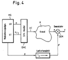
- a modulation signal generator MG generates a modulation signal consisting of bits b0 and b1 with the values ⁇ and ⁇ / 2. After conversion via a digital / analog converter DAC, this modulation signal controls the phase modulator PM (see FIG. 3) as signal PMS and thus, in short, the "gyro" K.
- bit a0 has the significance ⁇ ; all higher-order bits are suppressed, so that a modulo-2 ⁇ operation automatically results in the D / A converter DAC.
- the output signal PMS of the digital / analog converter DAC passes through the interferometer arrangement or the gyro path and reaches the input of a demodulator DEM as a signal e proportional to the received light intensity I.
- the modulation signal generator MG supplies the required demodulation signal d, which reaches the demodulator DEM after a delay compensation T Laufzeit.
- the transit time compensation T0 compensates for the resulting signal transit times, i.e.
- the runtime compensation ensures that the demodulation signal d supplied by the modulation signal generator MG "matches" the received signal e as the runtime-corrected demodulation signal d '.
- the modulation signal generator MG contains a random number generator from which the signals b0, b1 and d are derived.
- permanently stored signal patterns can also be used, which are put together in such a way that the required statistical independence is obtained. The following description is based on the solution with a random number generator, as shown in a block diagram in FIG. 5.
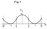
- the reversal points of the slope to be controlled are at odd multiples of ⁇ / 2.
- the interferometer phase consists of the difference between the current modulation phase p (n) and the previous modulator phase p (n-1). So that this difference is always an odd multiple of ⁇ / 2, p (n) must alternately be an even or odd multiple of ⁇ / 2, ie the bit b1 supplied by the modulation signal generator MG with the value ⁇ / 2 must constantly oscillate .
- b1 (n) ⁇ ... 0.1,0,1,0,1,0,1 ... ⁇
- bit b0 supplied by the modulation signal generator MG is initially arbitrary and can be used as a degree of freedom for the selection of points with a positive or negative slope of the interferometer characteristic.
- This sign signal generated in this way (cf. FIG. 5) is used for demodulation of the received signal after it has passed the transit time compensation T0.
- the structure of the modulation signal generator MG that follows from the above equations is shown in FIG. 5.
- the signal d (n) is statistically independent of s (n), although s (n) is used to generate it. When d (n) is formed, however, s (n) is completely scrambled again by multiplying it by the product r (n) ⁇ r (n-1) formed from random numbers.
- d (n) is statistically independent of all signals occurring in the modulation process in the linear sense, so that the requirements set out at the beginning are fulfilled.
- FIG. 6 shows a block diagram structure corresponding to FIG. 3 of a rotation rate sensor in an open-loop configuration, but with statistical generation of the modulation signal for the phase modulator PM according to the invention.
- the assemblies already known from the explanation of FIG. 3 are not described again.
- the oscillator OSC according to FIG. 3 is replaced by the modulation signal generator MG explained with reference to FIGS. 4 and 5.
- the demodulation signal d passes through the runtime compensation LZ and acts as a runtime corrected signal d 'on the synchronous signal input of the synchronous demodulator SYNCD.
- the signals b0 or b1, generated according to the explanations for FIG. 5, reach the D / A converter DA, as described above with reference to FIG. 4.
- the invention provides a modulation method for the control signal of a phase modulator of a fiber-optic ring interferometer for rotation rate measurement, which avoids the bias errors caused by electromagnetic coupling, as occur in the prior art, without increasing the necessary modulation range for the phase modulator.
Landscapes
- Physics & Mathematics (AREA)
- Engineering & Computer Science (AREA)
- Optics & Photonics (AREA)
- Electromagnetism (AREA)
- Power Engineering (AREA)
- General Physics & Mathematics (AREA)
- Radar, Positioning & Navigation (AREA)
- Remote Sensing (AREA)
- Gyroscopes (AREA)
Priority Applications (5)
| Application Number | Priority Date | Filing Date | Title |
|---|---|---|---|
| DE59103693T DE59103693D1 (de) | 1991-02-11 | 1991-02-11 | Faseroptisches Sagnac-Interferometer mit digitaler Phasenmodulation zur Drehratenmessung. |
| EP91101872A EP0498902B1 (fr) | 1991-02-11 | 1991-02-11 | Interféromètre à fibre optique du type sagnac avec modulation digitale de phase pour la mesure de vitesse de rotation |
| CA002059025A CA2059025C (fr) | 1991-02-11 | 1992-01-08 | Interferometre de sagnac a fibre optique a modulation de phase numerique pour mesurer les vitesses de rotation |
| US07/828,722 US5214488A (en) | 1991-02-11 | 1992-01-31 | Fiber optic sagnac interferometer with digital phase modulation for measuring rotation rate |
| JP4023816A JPH0749964B2 (ja) | 1991-02-11 | 1992-02-10 | 回転速度を測定するためのファイバオプティックサニャック干渉計 |
Applications Claiming Priority (1)
| Application Number | Priority Date | Filing Date | Title |
|---|---|---|---|
| EP91101872A EP0498902B1 (fr) | 1991-02-11 | 1991-02-11 | Interféromètre à fibre optique du type sagnac avec modulation digitale de phase pour la mesure de vitesse de rotation |
Publications (2)
| Publication Number | Publication Date |
|---|---|
| EP0498902A1 true EP0498902A1 (fr) | 1992-08-19 |
| EP0498902B1 EP0498902B1 (fr) | 1994-11-30 |
Family
ID=8206396
Family Applications (1)
| Application Number | Title | Priority Date | Filing Date |
|---|---|---|---|
| EP91101872A Expired - Lifetime EP0498902B1 (fr) | 1991-02-11 | 1991-02-11 | Interféromètre à fibre optique du type sagnac avec modulation digitale de phase pour la mesure de vitesse de rotation |
Country Status (5)
| Country | Link |
|---|---|
| US (1) | US5214488A (fr) |
| EP (1) | EP0498902B1 (fr) |
| JP (1) | JPH0749964B2 (fr) |
| CA (1) | CA2059025C (fr) |
| DE (1) | DE59103693D1 (fr) |
Cited By (1)
| Publication number | Priority date | Publication date | Assignee | Title |
|---|---|---|---|---|
| DE19629260C1 (de) * | 1996-07-19 | 1998-02-26 | Litef Gmbh | Elektrooptischer Phasenmodulator mit richtungsunabhängiger Impulsantwort, Anordnung von elektrooptischen Phasenmodulatoren und Verwendung eines elektrooptischen Phasenmodulators |
Families Citing this family (15)
| Publication number | Priority date | Publication date | Assignee | Title |
|---|---|---|---|---|
| US5400142A (en) * | 1994-05-03 | 1995-03-21 | Alliedsignal Inc. | Fiber optic angular rate sensor including digital phase modulation |
| US5530545A (en) * | 1994-07-29 | 1996-06-25 | Litton Systems, Inc. | Method for reducing random walk in fiber optic gyroscopes |
| US5850286A (en) * | 1997-05-12 | 1998-12-15 | Litton Systems, Inc. | Fiber optic gyro with optical intensity spike suppression |
| RU2124185C1 (ru) * | 1997-05-13 | 1998-12-27 | Михаил Афанасьевич Новиков | Оптический гироскоп с пассивным кольцевым резонатором |
| US5883716A (en) * | 1997-07-15 | 1999-03-16 | Litton Systems, Inc. | Rate control loop for fiber optic gyroscope |
| US6002481A (en) * | 1998-04-08 | 1999-12-14 | Honeywell, Inc. | Fiber optic gyro with noise dither circuit for enhancing A/D conversion resolution |
| JP3607862B2 (ja) * | 2000-09-29 | 2005-01-05 | 株式会社日立製作所 | 燃料電池 |
| EP1561768B8 (fr) * | 2002-10-08 | 2010-02-17 | Toyo Boseki Kabushiki Kaisha | Compose de polyarylene ether contenant un groupe acide sulfonique, composition le contenant et procede pour leur fabrication |
| DE102007005108A1 (de) | 2007-02-01 | 2008-08-07 | BSH Bosch und Siemens Hausgeräte GmbH | Zugmittelantrieb für ein Haushaltsgerät |
| CN101246009B (zh) * | 2008-02-29 | 2010-08-18 | 北京航空航天大学 | 基于四态马尔可夫链的数字闭环光纤陀螺随机调制方法 |
| DE102015004039A1 (de) * | 2015-03-27 | 2016-09-29 | Northrop Grumman Litef Gmbh | Mittelwertfrei gesteuerter Phasenmodulator für faseroptische Kreisel und faseroptischer Kreisel |
| US20180356546A1 (en) | 2015-12-10 | 2018-12-13 | Wojskowa Akademia Techniczna Im. Jaroslawa Dabrowskiego | Method of measurement and apparatus for measurement of amplitude ratio of two first harmonics of the signal obtained from sagnac system |
| CN106767937B (zh) * | 2016-11-29 | 2019-06-28 | 武汉理工光科股份有限公司 | 调谐式光纤光栅波长解调仪的实时修正方法 |
| DE102020213286A1 (de) * | 2020-10-21 | 2022-04-21 | Robert Bosch Gesellschaft mit beschränkter Haftung | Verfahren zur Bestimmung einer Phasenlage eines Drehratensignals oder eines Quadratursignals, Verfahren zur Anpassung einer Demodulationsphase und Drehratensensor |
| CN114545018B (zh) * | 2022-02-22 | 2024-01-30 | 中国工程物理研究院总体工程研究所 | 一种光纤破片测速装置及测速方法 |
Citations (1)
| Publication number | Priority date | Publication date | Assignee | Title |
|---|---|---|---|---|
| GB2227833A (en) * | 1988-03-09 | 1990-08-08 | British Aerospace | Fibre-optic gyroscope |
Family Cites Families (1)
| Publication number | Priority date | Publication date | Assignee | Title |
|---|---|---|---|---|
| EP0441998B1 (fr) * | 1990-02-12 | 1993-06-02 | LITEF GmbH | Interféromètre de Sagnac à fibre optique avec annulation numérique de déphasage pour la mesure de la vitesse de rotation |
-
1991
- 1991-02-11 DE DE59103693T patent/DE59103693D1/de not_active Expired - Fee Related
- 1991-02-11 EP EP91101872A patent/EP0498902B1/fr not_active Expired - Lifetime
-
1992
- 1992-01-08 CA CA002059025A patent/CA2059025C/fr not_active Expired - Lifetime
- 1992-01-31 US US07/828,722 patent/US5214488A/en not_active Expired - Lifetime
- 1992-02-10 JP JP4023816A patent/JPH0749964B2/ja not_active Expired - Lifetime
Patent Citations (1)
| Publication number | Priority date | Publication date | Assignee | Title |
|---|---|---|---|---|
| GB2227833A (en) * | 1988-03-09 | 1990-08-08 | British Aerospace | Fibre-optic gyroscope |
Cited By (1)
| Publication number | Priority date | Publication date | Assignee | Title |
|---|---|---|---|---|
| DE19629260C1 (de) * | 1996-07-19 | 1998-02-26 | Litef Gmbh | Elektrooptischer Phasenmodulator mit richtungsunabhängiger Impulsantwort, Anordnung von elektrooptischen Phasenmodulatoren und Verwendung eines elektrooptischen Phasenmodulators |
Also Published As
| Publication number | Publication date |
|---|---|
| US5214488A (en) | 1993-05-25 |
| CA2059025C (fr) | 2001-01-02 |
| JPH0749964B2 (ja) | 1995-05-31 |
| EP0498902B1 (fr) | 1994-11-30 |
| CA2059025A1 (fr) | 1992-08-12 |
| JPH0688834A (ja) | 1994-03-29 |
| DE59103693D1 (de) | 1995-01-12 |
Similar Documents
| Publication | Publication Date | Title |
|---|---|---|
| EP0551537B1 (fr) | Méthode et dispositif pour mesurer vitesse de rotation par un interféromètre à fibre optique du type sagnac | |
| EP0441998B1 (fr) | Interféromètre de Sagnac à fibre optique avec annulation numérique de déphasage pour la mesure de la vitesse de rotation | |
| EP0498902B1 (fr) | Interféromètre à fibre optique du type sagnac avec modulation digitale de phase pour la mesure de vitesse de rotation | |
| DE3326555C2 (fr) | ||
| DE3829731C2 (fr) | ||
| DE69622103T2 (de) | Optisches Abstandsmesssystem mit Triangulation | |
| DE3447721C2 (fr) | ||
| DE3140110C2 (fr) | ||
| CH652245A5 (de) | Ringlaser. | |
| EP3274658B1 (fr) | Modulateur de phase commandé à valeur moyenne nulle pour gyroscopes à fibre optique et gyroscope à fibre optique | |
| DE69624057T2 (de) | Faseroptischer Kreisel | |
| DE69619552T2 (de) | Vorrichtung zur unterdrückung von kohärenten pickupfehlern | |
| DE3220389A1 (de) | Verfahren und einrichtung zur messung der rotationsgeschwindigkeit unter ausnutzung des sagnac-effekts | |
| EP0436052B1 (fr) | nnterféromètre de Sagnac à fibre optique avec rappel numérique de déphasage pour la mesure de la vitesse de rotation | |
| DE2941618C2 (fr) | ||
| DE69010810T2 (de) | Optischer Faserkreisel. | |
| DE1614662B2 (de) | Ringlaser | |
| DE102015106550B3 (de) | Faseroptisches System und Verfahren zur Reduktion von Biasfehlern in einem solchen faseroptischen System | |
| DE19630344A1 (de) | Faseroptischer Kreisel | |
| EP0113889B1 (fr) | Dispositif pour mesurer la vitesse de rotation | |
| DE69009144T2 (de) | Optischer Faserkreisel. | |
| DE3239068A1 (de) | Einrichtung zur messung der rotationsgeschwindigkeit | |
| EP0483501B1 (fr) | Interféromètre de sagnac à fibre optique pour la mesure de la vitesse de rotation | |
| DE69122524T2 (de) | Interferenzsensoren und Verfahren zur Messung einer physikalischen Grösse mit derartigen Sensoren, sowie Kfz Leitsystem. | |
| EP0113890A2 (fr) | Dispositif pour mesurer la vitesse de rotation |
Legal Events
| Date | Code | Title | Description |
|---|---|---|---|
| PUAI | Public reference made under article 153(3) epc to a published international application that has entered the european phase |
Free format text: ORIGINAL CODE: 0009012 |
|
| 17P | Request for examination filed |
Effective date: 19911106 |
|
| AK | Designated contracting states |
Kind code of ref document: A1 Designated state(s): CH DE ES FR GB IT LI |
|
| 17Q | First examination report despatched |
Effective date: 19921202 |
|
| GRAA | (expected) grant |
Free format text: ORIGINAL CODE: 0009210 |
|
| AK | Designated contracting states |
Kind code of ref document: B1 Designated state(s): CH DE ES FR GB IT LI |
|
| PG25 | Lapsed in a contracting state [announced via postgrant information from national office to epo] |
Ref country code: ES Free format text: THE PATENT HAS BEEN ANNULLED BY A DECISION OF A NATIONAL AUTHORITY Effective date: 19941130 |
|
| ITF | It: translation for a ep patent filed | ||
| REF | Corresponds to: |
Ref document number: 59103693 Country of ref document: DE Date of ref document: 19950112 |
|
| GBT | Gb: translation of ep patent filed (gb section 77(6)(a)/1977) |
Effective date: 19950118 |
|
| PG25 | Lapsed in a contracting state [announced via postgrant information from national office to epo] |
Ref country code: CH Effective date: 19950228 Ref country code: LI Effective date: 19950228 |
|
| ET | Fr: translation filed | ||
| PLBE | No opposition filed within time limit |
Free format text: ORIGINAL CODE: 0009261 |
|
| STAA | Information on the status of an ep patent application or granted ep patent |
Free format text: STATUS: NO OPPOSITION FILED WITHIN TIME LIMIT |
|
| 26N | No opposition filed | ||
| REG | Reference to a national code |
Ref country code: GB Ref legal event code: IF02 |
|
| PG25 | Lapsed in a contracting state [announced via postgrant information from national office to epo] |
Ref country code: IT Free format text: LAPSE BECAUSE OF NON-PAYMENT OF DUE FEES;WARNING: LAPSES OF ITALIAN PATENTS WITH EFFECTIVE DATE BEFORE 2007 MAY HAVE OCCURRED AT ANY TIME BEFORE 2007. THE CORRECT EFFECTIVE DATE MAY BE DIFFERENT FROM THE ONE RECORDED. Effective date: 20050211 |
|
| PGFP | Annual fee paid to national office [announced via postgrant information from national office to epo] |
Ref country code: DE Payment date: 20090226 Year of fee payment: 19 |
|
| PGFP | Annual fee paid to national office [announced via postgrant information from national office to epo] |
Ref country code: GB Payment date: 20090223 Year of fee payment: 19 |
|
| PGFP | Annual fee paid to national office [announced via postgrant information from national office to epo] |
Ref country code: FR Payment date: 20090217 Year of fee payment: 19 |
|
| GBPC | Gb: european patent ceased through non-payment of renewal fee |
Effective date: 20100211 |
|
| REG | Reference to a national code |
Ref country code: FR Ref legal event code: ST Effective date: 20101029 |
|
| PG25 | Lapsed in a contracting state [announced via postgrant information from national office to epo] |
Ref country code: FR Free format text: LAPSE BECAUSE OF NON-PAYMENT OF DUE FEES Effective date: 20100301 |
|
| PG25 | Lapsed in a contracting state [announced via postgrant information from national office to epo] |
Ref country code: DE Free format text: LAPSE BECAUSE OF NON-PAYMENT OF DUE FEES Effective date: 20100901 |
|
| PG25 | Lapsed in a contracting state [announced via postgrant information from national office to epo] |
Ref country code: GB Free format text: LAPSE BECAUSE OF NON-PAYMENT OF DUE FEES Effective date: 20100211 |