EP0498961B1 - Dispositif de séchage du bois - Google Patents
Dispositif de séchage du bois Download PDFInfo
- Publication number
- EP0498961B1 EP0498961B1 EP91121843A EP91121843A EP0498961B1 EP 0498961 B1 EP0498961 B1 EP 0498961B1 EP 91121843 A EP91121843 A EP 91121843A EP 91121843 A EP91121843 A EP 91121843A EP 0498961 B1 EP0498961 B1 EP 0498961B1
- Authority
- EP
- European Patent Office
- Prior art keywords
- air
- drying
- circulating
- fans
- wood
- Prior art date
- Legal status (The legal status is an assumption and is not a legal conclusion. Google has not performed a legal analysis and makes no representation as to the accuracy of the status listed.)
- Expired - Lifetime
Links
Images
Classifications
-
- F—MECHANICAL ENGINEERING; LIGHTING; HEATING; WEAPONS; BLASTING
- F26—DRYING
- F26B—DRYING SOLID MATERIALS OR OBJECTS BY REMOVING LIQUID THEREFROM
- F26B21/00—Arrangements for supplying or controlling air or other gases for drying solid materials or objects
- F26B21/20—Circulating air or gases in closed cycles, e.g. wholly within the drying enclosure
-
- F—MECHANICAL ENGINEERING; LIGHTING; HEATING; WEAPONS; BLASTING
- F26—DRYING
- F26B—DRYING SOLID MATERIALS OR OBJECTS BY REMOVING LIQUID THEREFROM
- F26B5/00—Drying solid materials or objects by processes not involving the application of heat
- F26B5/04—Drying solid materials or objects by processes not involving the application of heat by evaporation or sublimation of moisture under reduced pressure, e.g. in a vacuum
-
- F—MECHANICAL ENGINEERING; LIGHTING; HEATING; WEAPONS; BLASTING
- F26—DRYING
- F26B—DRYING SOLID MATERIALS OR OBJECTS BY REMOVING LIQUID THEREFROM
- F26B9/00—Machines or apparatus for drying solid materials or objects at rest or with only local agitation; Domestic airing cupboards
- F26B9/06—Machines or apparatus for drying solid materials or objects at rest or with only local agitation; Domestic airing cupboards in stationary drums or chambers
Definitions
- the invention relates to a device for drying wood or other goods, with an elongated, cylindrical outer housing and a front cover, an elongated cylindrical heating shield arranged coaxially inside the housing, which encloses the actual drying chamber and on the outside with the
- the inner casing of the circulating air duct is limited, as well as with a vacuum device and an air circulation device on the end face opposite the sealing cover.
- Such a device is known from DE-A-35 43 248.
- the air warmed up by the heating shield is blown lengthways through the wood stacked in the drying room enclosed by the heating shield.
- the wood has to be re-stacked from the storage location, since it is usually stored on continuous strips.
- the object of the present invention is to redesign a device known for longitudinal ventilation with simple means in such a way that the introduced wood can be dried more quickly and more uniformly without the wood being stacked for a drying cycle got to.
- the drying space is closed at the end toward the air circulation device with a partition wall covering the end of the heating shield, that the space between the heating shield and the outer housing is divided by radial partition walls into an upper, a lower and two lateral air circulation ducts and that Heating shield in the area of the side air circulation ducts, which are sealed off from the closure cover, has air slots for cross ventilation of the wood stacked in the drying space, and the drying air is returned from the loading end of the drying space to the air circulation device via the upper air circulation duct.
- the heating shield has transverse slots on one side only in the front area of one side air circulation duct and on the other side only in the rear area of the opposite air circulation duct.
- the recirculating air duct located below has an elongated cooling register and can be acted upon parallel to the lateral recirculating air ducts, so that part of the circulated air is always recooled and freed from the water vapor carried by falling below the dew point.
- the air circulation device consists of a plurality of separately controllable fans.
- a method for operating such a drying device has proven particularly expedient, in which, according to the invention, the air is circulated only by a part of the fans in the warm-up phase and by a larger number of fans in the dry phase with the generation of a vacuum.
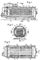
- the drying device has an outer cylindrical housing 1 with an end closure cover 2 as the loading opening and a closed end wall 3, on the inside of which an air circulation device 4 in the form of several fans is arranged.
- An elongated cylindrical heating shield 5 is arranged inside the cylindrical insulated housing 1 and coaxially therewith, which consists of a double jacket with heating pipes in between and which is heated from the outside via a heating boiler.
- the interior of this heating shield 5 forms the actual drying chamber 6, in which, as can be seen from FIG. 2, corresponding long timber 7 is stacked on a carriage 8 and is retracted via the opened closure cover 2.
- the drying chamber 6 or the heating shield 5 is closed on its inner end face opposite the fans 4 with a closed end wall 9. Furthermore, the annular space enclosed by the outer jacket of the heating shield 5 and by the inner surface of the housing 1 - as can be seen in particular from the cross section according to FIG. 2 - is divided by radial partition walls 10, 11, 12, 13, so that an upper air circulation duct 14, two side air ducts 15 and 16 and a lower air duct 17 are formed.
- the side air circulation ducts at the end of the heating shield 5 on the cover side are sealed off via corresponding transverse walls 18 and 19 from the front space 20 between the closure cover 2 and the end of the heating shield 5, while the actual drying space 6 and the upper and lower air circulation ducts 14 and 17 lead to the end space 20 are open.
- the heating shield 5 has air slots 21 and 22 leading radially inwards in the area covered laterally by the air circulation ducts 15 and 16 for transverse ventilation of the wood stack 7. It is included for optimal airflow and swirling Of particular advantage if, for example, starting from the left air circulation duct 15, the air slots 21 are only provided in the front half of the heating shield 5 adjacent to the fans 4, while on the opposite side, starting from the air circulation duct 16, the air slots 22 are only provided in the rear half of the heating shield 5 are provided. This means that the cross-flowing air does not encounter a counterflow, but can extend over the entire width of the stack.
- a vacuum pump 24 is also provided for generating a vacuum in the drying room 6.
- cooling registers 25 are arranged in the lower air circulation duct 17 in order to cool back part of the moisture-laden air and, in doing so, to achieve a precipitation of the water vapor loading by falling below the dew point.
- a part of the circulating air is conveyed by the fans 4 practically in a bypass through the lower circulating air duct 17 to the front space 20, this proportion of air sweeping along the cooling register 25, is cooled there and releases a large part of the absorbed moisture.
Landscapes
- Engineering & Computer Science (AREA)
- Mechanical Engineering (AREA)
- General Engineering & Computer Science (AREA)
- Health & Medical Sciences (AREA)
- Life Sciences & Earth Sciences (AREA)
- Molecular Biology (AREA)
- Drying Of Solid Materials (AREA)
Claims (7)
- Installation de séchage du bois ou d'autres produits, comprenant une enveloppe (1) extérieure, oblongue, cylindrique et un couvercle (2) de fermeture du côté frontal, un bouclier (6) de chauffage qui entoure la chambre de séchage proprement dite et dont la face extérieure délimite, avec la surface latérale intérieure de l'enveloppe, des canaux de circulation de l'air, ainsi qu'un dispositif de mise sous vide et un dispositif (4) de recirculation de l'air sur le côté frontal opposé au couvercle (7) de fermeture, caractérisée en ce que la chambre de séchage (6) est fermée du côté frontal en direction du dispositif (4) de recirculation de l'air par une paroi frontale (6) recouvrant l'extrémité (5) du bouclier thermique, en ce que l'intervalle compris entre le bouclier thermique (5) et l'enveloppe (1) est subdivisé par des cloisons (10,11,12,13) radiales en un canal (14) supérieur, en un canal (17) inférieur et en deux canaux (15,16) latéraux de recirculation de l'air, et en ce que le bouclier thermique (5) comporte, dans la région des canaux (15,16) de recirculation de l'air fermés latéralement en direction du couvercle (2) de fermeture, des fentes (21,22) d'aération transversales du bois (7) empilé dans la chambre (6) de séchage, et l'air de séchage est recyclé de l'extrémité de chargement (20) de la chambre (6) de séchage au dispositif (4) de recirculation de l'air en passant par le canal (14) supérieur de recirculation de l'air.
- Dispositif de séchage suivant la revendication 1, caractérisé en ce que le bouclier (5) thermique comporte des fentes (21,22) transversales d'un côté que dans la partie avant de l'un des canaux (15) latéraux de recirculation de l'air, et de l'autre côté que dans la partie arrière du canal (16) opposé de recirculation de l'air.
- Dispositif de séchage suivant la revendication 2, caractérisé en ce que la surface de passage et le nombre des fentes (21,22) transversales sont réglables.
- Dispositif de séchage suivant la revendication 1, caractérisé en ce que le canal (17) inférieur de recirculation de l'air comporte un registre de refroidissement oblong et peut être alimenté parallèlement aux canaux (15,16) latéraux de recirculation de l'air.
- Dispositif de séchage suivant la revendication 1, caractérisé en ce que le dispositif (4) de recirculation de l'air est constitué de plusieurs ventilateurs pouvant être commandés indépendamment.
- Procédé pour faire fonctionner un dispositif de séchage suivant l'une des revendications 1 à 5, caractérisé en ce qu'il consiste à ne faire recirculer l'air dans la phase de chauffage que par une partie des ventilateurs, et dans la phase de séchage avec production d'un vide par un plus grand nombre de ventilateurs.
- Procédé suivant la revendication 6, caractérisé en ce que le passage de l'air peut passer d'un fonctionnement en aspiration à un fonctionnement en refoulement par inversion des ventilateurs.
Priority Applications (1)
| Application Number | Priority Date | Filing Date | Title |
|---|---|---|---|
| AT91121843T ATE102336T1 (de) | 1991-02-15 | 1991-12-19 | Vorrichtung zum trocknen von holz. |
Applications Claiming Priority (2)
| Application Number | Priority Date | Filing Date | Title |
|---|---|---|---|
| DE4104768 | 1991-02-15 | ||
| DE4104768A DE4104768C1 (fr) | 1991-02-15 | 1991-02-15 |
Publications (2)
| Publication Number | Publication Date |
|---|---|
| EP0498961A1 EP0498961A1 (fr) | 1992-08-19 |
| EP0498961B1 true EP0498961B1 (fr) | 1994-03-02 |
Family
ID=6425167
Family Applications (1)
| Application Number | Title | Priority Date | Filing Date |
|---|---|---|---|
| EP91121843A Expired - Lifetime EP0498961B1 (fr) | 1991-02-15 | 1991-12-19 | Dispositif de séchage du bois |
Country Status (3)
| Country | Link |
|---|---|
| EP (1) | EP0498961B1 (fr) |
| AT (1) | ATE102336T1 (fr) |
| DE (2) | DE4104768C1 (fr) |
Families Citing this family (1)
| Publication number | Priority date | Publication date | Assignee | Title |
|---|---|---|---|---|
| DE19543412A1 (de) * | 1995-11-21 | 1997-05-22 | Waldner Gmbh & Co Hermann | Trockner, insbesondere für die chemische oder pharmazeutische Industrie |
Family Cites Families (9)
| Publication number | Priority date | Publication date | Assignee | Title |
|---|---|---|---|---|
| FR986549A (fr) * | 1949-03-11 | 1951-08-01 | Perfectionnements aux séchoirs à bois | |
| IT1032926B (it) * | 1975-05-19 | 1979-06-20 | Pagnozzi Ernesto Guglielmo | Procedimento a vuoto per essiccare legname massiccio particolarmente per essiccare legname delicato e o facilmente collassabile |
| IT1071276B (it) * | 1976-05-12 | 1985-04-02 | Pagnozzi Ernesto Guglielmo | Perfezionamenti nei procedimenti e negli impianti di essiccazione del legname..particolarmente negli impianti che impiegano il vuoto |
| JPS53103261A (en) * | 1977-02-19 | 1978-09-08 | Kitagawa Iron Works Co | Method of drying wooden products and apparatus therefor |
| ES8604347A1 (es) * | 1984-10-18 | 1986-02-01 | Aranguren Ind Sa | Maquina para el secado de la madera. |
| DE3543248A1 (de) * | 1985-12-06 | 1987-06-11 | Josef Kronseder | Vorrichtung zum trocknen von holz |
| FR2614682A1 (fr) * | 1987-04-30 | 1988-11-04 | Giuliani Lando | Procede et dispositif de sechage d'un corps dans lequel une partie de l'humidite a extraire est retenue dans des cellules fermees |
| DE8812056U1 (de) * | 1988-09-23 | 1989-01-19 | Wolf Stahlbau Gmbh U. Co Kg, 8069 Geisenfeld | Vorrichtung zum Trocknen von Hopfen in Hopfentrocknungsanlagen |
| DE9005827U1 (de) * | 1990-05-22 | 1990-08-23 | Kronseder, Josef, 8313 Vilsbiburg | Vorrichtung zum Trocknen von Holz |
-
1991
- 1991-02-15 DE DE4104768A patent/DE4104768C1/de not_active Expired - Lifetime
- 1991-12-19 EP EP91121843A patent/EP0498961B1/fr not_active Expired - Lifetime
- 1991-12-19 AT AT91121843T patent/ATE102336T1/de not_active IP Right Cessation
- 1991-12-19 DE DE91121843T patent/DE59101105D1/de not_active Expired - Fee Related
Also Published As
| Publication number | Publication date |
|---|---|
| DE4104768C1 (fr) | 1992-03-12 |
| ATE102336T1 (de) | 1994-03-15 |
| DE59101105D1 (de) | 1994-04-07 |
| EP0498961A1 (fr) | 1992-08-19 |
Similar Documents
| Publication | Publication Date | Title |
|---|---|---|
| DE4208913C2 (de) | Vorrichtung zum Trocknen von Schnittholz | |
| DE3027900C2 (de) | Luftgekühlter Wärmetauscher für Haushalt-Wäschetrockner | |
| EP0167899B1 (fr) | Dispositif de séchage, notamment pour le bois de charpente | |
| DE4228699C2 (de) | Vorrichtung zum chargenweisen Trocknen von Schnittholz | |
| DE3543248C2 (fr) | ||
| DE3134506C2 (fr) | ||
| EP0592973B1 (fr) | Dispositif de séchage du bois ou d'autres matériaux solides | |
| EP0498961B1 (fr) | Dispositif de séchage du bois | |
| EP0141227B1 (fr) | Séchoir vertical | |
| EP4056940A1 (fr) | Dispositif et procédé de séchage d'objets et/ou de matières, en particulier de bois | |
| DE3013703A1 (de) | Trockenverfahren mit energierueckgewinnung mittelsn waermepumpe | |
| DE3900074C2 (de) | Wäschetrockner | |
| DE19743378A1 (de) | Hordentrockner | |
| DE1927839A1 (de) | Trockenanlage fuer keramische,insbesondere grobkeramische Erzeugnisse | |
| EP0082358B1 (fr) | Séchoir à tambour | |
| EP0437272A1 (fr) | Séchoir vertical | |
| EP0458219A1 (fr) | Dispositif pour le séchage du bois | |
| DE3714519A1 (de) | Vortrocknungsofen fuer holz | |
| DE69303990T2 (de) | Energiesparender Wäschetrockner | |
| DD207113A3 (de) | Heissmuldenmangel, insbesondere mehrmuldenmangel | |
| DE29611521U1 (de) | Vorrichtung zum Trocknen von Holz | |
| DE3710787A1 (de) | Vorrichtung zur waermebehandlung von textilbahnen und dgl. | |
| DE102024131491A1 (de) | Trockner für eine textile Warenbahn | |
| DE69510042T2 (de) | Verfahren und vorrichtung zum trocknen von holz | |
| DE3616411A1 (de) | Verfahren und vorrichtung zur konvektiven trocknung und kuehlung rieselfaehiger schuettgueter |
Legal Events
| Date | Code | Title | Description |
|---|---|---|---|
| PUAI | Public reference made under article 153(3) epc to a published international application that has entered the european phase |
Free format text: ORIGINAL CODE: 0009012 |
|
| AK | Designated contracting states |
Kind code of ref document: A1 Designated state(s): AT CH DE FR IT LI |
|
| 17P | Request for examination filed |
Effective date: 19920904 |
|
| 17Q | First examination report despatched |
Effective date: 19930426 |
|
| GRAA | (expected) grant |
Free format text: ORIGINAL CODE: 0009210 |
|
| AK | Designated contracting states |
Kind code of ref document: B1 Designated state(s): AT CH DE FR IT LI |
|
| PG25 | Lapsed in a contracting state [announced via postgrant information from national office to epo] |
Ref country code: IT Free format text: LAPSE BECAUSE OF FAILURE TO SUBMIT A TRANSLATION OF THE DESCRIPTION OR TO PAY THE FEE WITHIN THE PRE;WARNING: LAPSES OF ITALIAN PATENTS WITH EFFECTIVE DATE BEFORE 2007 MAY HAVE OCCURRED AT ANY TIME BEFORE 2007. THE CORRECT EFFECTIVE DATE MAY BE DIFFERENT FROM THE ONE RECORDED.SCRIBED TIME-LIMIT Effective date: 19940302 |
|
| REF | Corresponds to: |
Ref document number: 102336 Country of ref document: AT Date of ref document: 19940315 Kind code of ref document: T |
|
| REF | Corresponds to: |
Ref document number: 59101105 Country of ref document: DE Date of ref document: 19940407 |
|
| ET | Fr: translation filed | ||
| PG25 | Lapsed in a contracting state [announced via postgrant information from national office to epo] |
Ref country code: CH Effective date: 19941231 Ref country code: LI Effective date: 19941231 |
|
| PLBE | No opposition filed within time limit |
Free format text: ORIGINAL CODE: 0009261 |
|
| STAA | Information on the status of an ep patent application or granted ep patent |
Free format text: STATUS: NO OPPOSITION FILED WITHIN TIME LIMIT |
|
| 26N | No opposition filed | ||
| REG | Reference to a national code |
Ref country code: CH Ref legal event code: PL |
|
| PGFP | Annual fee paid to national office [announced via postgrant information from national office to epo] |
Ref country code: FR Payment date: 19991217 Year of fee payment: 9 |
|
| PGFP | Annual fee paid to national office [announced via postgrant information from national office to epo] |
Ref country code: AT Payment date: 19991220 Year of fee payment: 9 |
|
| PGFP | Annual fee paid to national office [announced via postgrant information from national office to epo] |
Ref country code: DE Payment date: 20000105 Year of fee payment: 9 |
|
| PG25 | Lapsed in a contracting state [announced via postgrant information from national office to epo] |
Ref country code: AT Free format text: LAPSE BECAUSE OF NON-PAYMENT OF DUE FEES Effective date: 20001219 |
|
| PG25 | Lapsed in a contracting state [announced via postgrant information from national office to epo] |
Ref country code: FR Free format text: LAPSE BECAUSE OF NON-PAYMENT OF DUE FEES Effective date: 20010831 |
|
| REG | Reference to a national code |
Ref country code: FR Ref legal event code: ST |
|
| PG25 | Lapsed in a contracting state [announced via postgrant information from national office to epo] |
Ref country code: DE Free format text: LAPSE BECAUSE OF NON-PAYMENT OF DUE FEES Effective date: 20011002 |