EP0499007A1 - Federbelastetes Lenkrollensystem für schwere Lasten zur Lagerung einer fluidisierten Patientenstützvorrichtung - Google Patents
Federbelastetes Lenkrollensystem für schwere Lasten zur Lagerung einer fluidisierten Patientenstützvorrichtung Download PDFInfo
- Publication number
- EP0499007A1 EP0499007A1 EP91402563A EP91402563A EP0499007A1 EP 0499007 A1 EP0499007 A1 EP 0499007A1 EP 91402563 A EP91402563 A EP 91402563A EP 91402563 A EP91402563 A EP 91402563A EP 0499007 A1 EP0499007 A1 EP 0499007A1
- Authority
- EP
- European Patent Office
- Prior art keywords
- caster
- support system
- casters
- disposed
- sleeve
- Prior art date
- Legal status (The legal status is an assumption and is not a legal conclusion. Google has not performed a legal analysis and makes no representation as to the accuracy of the status listed.)
- Granted
Links
Images

Classifications
-
- B—PERFORMING OPERATIONS; TRANSPORTING
- B60—VEHICLES IN GENERAL
- B60B—VEHICLE WHEELS; CASTORS; AXLES FOR WHEELS OR CASTORS; INCREASING WHEEL ADHESION
- B60B33/00—Castors in general ; Anti-clogging castors
- B60B33/0036—Castors in general ; Anti-clogging castors characterised by type of wheels
- B60B33/0042—Double or twin wheels
-
- A—HUMAN NECESSITIES
- A61—MEDICAL OR VETERINARY SCIENCE; HYGIENE
- A61G—TRANSPORT, PERSONAL CONVEYANCES, OR ACCOMMODATION SPECIALLY ADAPTED FOR PATIENTS OR DISABLED PERSONS; OPERATING TABLES OR CHAIRS; CHAIRS FOR DENTISTRY; FUNERAL DEVICES
- A61G1/00—Stretchers
- A61G1/04—Parts, details or accessories, e.g. head-, foot-, or like rests specially adapted for stretchers
- A61G1/042—Suspension means
-
- A—HUMAN NECESSITIES
- A61—MEDICAL OR VETERINARY SCIENCE; HYGIENE
- A61G—TRANSPORT, PERSONAL CONVEYANCES, OR ACCOMMODATION SPECIALLY ADAPTED FOR PATIENTS OR DISABLED PERSONS; OPERATING TABLES OR CHAIRS; CHAIRS FOR DENTISTRY; FUNERAL DEVICES
- A61G7/00—Beds specially adapted for nursing; Devices for lifting patients or disabled persons
- A61G7/05—Parts, details or accessories of beds
- A61G7/0528—Steering or braking devices for castor wheels
-
- B—PERFORMING OPERATIONS; TRANSPORTING
- B60—VEHICLES IN GENERAL
- B60B—VEHICLE WHEELS; CASTORS; AXLES FOR WHEELS OR CASTORS; INCREASING WHEEL ADHESION
- B60B33/00—Castors in general ; Anti-clogging castors
- B60B33/04—Castors in general ; Anti-clogging castors adjustable, e.g. in height; linearly shifting castors
- B60B33/045—Castors in general ; Anti-clogging castors adjustable, e.g. in height; linearly shifting castors mounted resiliently, by means of dampers
-
- A—HUMAN NECESSITIES
- A61—MEDICAL OR VETERINARY SCIENCE; HYGIENE
- A61G—TRANSPORT, PERSONAL CONVEYANCES, OR ACCOMMODATION SPECIALLY ADAPTED FOR PATIENTS OR DISABLED PERSONS; OPERATING TABLES OR CHAIRS; CHAIRS FOR DENTISTRY; FUNERAL DEVICES
- A61G7/00—Beds specially adapted for nursing; Devices for lifting patients or disabled persons
- A61G7/05—Parts, details or accessories of beds
- A61G7/057—Arrangements for preventing bed-sores or for supporting patients with burns, e.g. mattresses specially adapted therefor
- A61G7/05738—Arrangements for preventing bed-sores or for supporting patients with burns, e.g. mattresses specially adapted therefor with fluid-like particles, e.g. sand, mud, seeds, gel, beads
- A61G7/05746—Arrangements for preventing bed-sores or for supporting patients with burns, e.g. mattresses specially adapted therefor with fluid-like particles, e.g. sand, mud, seeds, gel, beads fluidised by air flow
-
- B—PERFORMING OPERATIONS; TRANSPORTING
- B60—VEHICLES IN GENERAL
- B60B—VEHICLE WHEELS; CASTORS; AXLES FOR WHEELS OR CASTORS; INCREASING WHEEL ADHESION
- B60B2200/00—Type of product being used or applied
- B60B2200/20—Furniture or medical appliances
- B60B2200/24—Beds
- B60B2200/242—Hospital beds
Definitions
- the present invention relates to fluidized patient support systems and more particularly to the rolling undercarriage for same.
- a fluidized patient support system typically weighs in the vicinity of 1,800 to 2,000 pounds when supporting a patient.
- An example of such fluidized patient support system is disclosed in U.S. Patent No. 4,942,635 to Hargest et al , which is hereby incorporated herein by this reference.
- Other examples of fluidized patient support systems are disclosed in U.S. Patent Nos. 3,428,973 to Hargest et al , 3,866,606 to Hargest , 4,483,029 to Paul , 4,564,965 to Goodwin , 4,637,083 to Goodwin , and 4,672,699 to Goodwin , the disclosures of each of the foregoing being hereby incorporated herein by this reference.
- Such systems must be mobile so that they can be moved to different locations within the health care facility as well as to permit their return periodically to a maintenance facility located off-site from the health care facility. Often such fluidized patient support systems must be moved while a patient is occupying the system. Because of the large amount of weight, such systems have relied upon heavy duty axles and wheels to render them mobile. In addition, heavy duty casters have been provided to render such systems mobile.
- an undercarriage system for a fluidized patient support system comprises
- an apparatus for supporting and transporting a fluidized patient support system above and across a floor.
- the undercarriage system apparatus of the present invention can include means for carrying the weight of the fluidized patient support system; means for rendering the weight carrying means sufficiently mobile so that the fluidized patient support system can be moved from place to place by being pushed by an attendant of average strength, manually across the floor and steered manually during such movement; and means for absorbing shock loads to the mobility means during movement of the fluidized support system.
- One embodiment of the weight carrying means can include a base frame that is configured and disposed to carry the weight of the fluidized patient support system.
- the base frame can be covered by a shroud for aesthetic purposes.
- the remaining structural components of the fluidized patient support system are connected directly or indirectly to the base frame.
- the mobility means includes a plurality of heavy duty casters connected to and supporting the weight carrying means.
- the base frame can be constructed with a cylindrical sleeve for receiving the central shaft of each caster.
- a separate sleeve can be provided at a sufficient number of locations so that a sufficient number of casters can be received at a number of different locations appropriate to provide a stable rolling platform for the fluidized patient support system.
- Each caster includes a shoulder portion disposed about the central shaft and configured and structured for carrying the load desired to be carried by the caster.
- Each caster also includes a wheel carriage rotatably mounted to swivel about the central shaft.
- Each caster also can include at least one caster wheel and preferably a pair of caster wheels mounted side-by-side to rotate about the wheel carriage.
- the particular dimensional relationships of the various components of the caster are designed to provide sufficient strength and maneuverability to perform the intended function.
- Needle roller bearings can be provided between the wheel carriage and the central shaft to permit the double wheels to be carried by the wheel carriage close together in a compact configuration that is well suited to facilitating swiveling of the wheels about the central shaft via the wheel carriage.
- Each caster can be provided with a manually actuatable brake.
- the shock absorbing means includes a disk spring, which can be configured in the form of a truncated cone.
- a separate disk spring is provided between the shoulder portion of each caster and the weight carrying means.
- a second disk spring is disposed between each caster and the weight carrying means so that the outermost edges of the pair of disk springs touches one another.
- Each disk spring desirably has a maximum load capacity rated at least 50% above the nominal load which the disk spring must carry.
- a disk spring with a two and one-eighth inch outside diameter and a one and one-eighth inch inside diameter can be provided with a 750 pound maximum load capacity over a maximum deflection distance of one-eighth inch.
- each disk spring has a very high load rating relative to a very small deflection length.
- An embodiment of the shock absorbing means also can include a threaded opening defined to extend radially into the central shaft of each caster.
- the height of the center line of the threaded opening above the shoulder portion of the caster is desirably about 1 inch.
- the shock absorbing means also can include at least one sleeve defined as part of the base frame and configured for receiving the central shaft of a caster.
- the shock absorbing means desirably includes a slot defined through the cylindrical wall of each sleeve and defining an opening configured to elongate in the axial direction of the cylindrical sleeve.
- the edges of the slot define a cam for receiving a cam follower which engages the edges of the slot and constrains the translational movement of the cam follower within the confines of the edges of the slot.
- the shock absorbing means also desirably includes a threaded cylindrical bolt configured to be screwed into the threaded opening of each central shaft of each caster.
- the bolt is configured in the form of a socket head shoulder screw having a threaded portion, a smooth shoulder portion wider than the threaded portion and just wide enough to be received within the slot defined in the cylindrical sleeve, and a head portion wider than the transverse diameter of the smooth portion of the bolt and wider than the width of the slot defined in the cylindrical sleeve.
- the threaded bolt can be inserted into the threaded opening after the central shaft is inserted into the sleeve of the base frame.
- the smooth portion of the bolt rides within the confines of the slot of the sleeve as the disk springs are compressed and uncompressed during shock absorbing events.
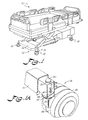
- FIG. 1 A preferred embodiment of the undercarriage system for a fluidized patient support system, which is indicated generally by the numeral 10, is shown in Fig. 1 and is represented generally by the designating numeral 12.
- the weight carrying means can include a base frame 14.
- base frame 14 is configured and disposed to carry the weight of fluidised patient support system 10.
- base frame 14 desirably is formed of heavy gauge steel.
- shroud 16 can be carried by base frame 14 and covers same. The remaining structural components of fluidized patient support system 10 are connected directly or indirectly to base frame 14.
- means are provided for rendering the weight carrying means sufficiently mobile so that the fluidized patient support system can be moved from place to place by being pushed by an attendant of average strength, manually across the floor and steered manually during such movement.
- a primary function of the mobility means is to facilitate movement of the patient support system by the normal personnel that would be available in the health care facility in which the patient support system is being used.
- the mobility means should empower such staffing personnel to maintain the patient support system stationary at a particular location and to render such system mobile so that it can be moved to a different location.
- the mobility means should permit the fluidized patient support system to be moved easily by being pushed and steered across the floor without herculean efforts being expended. Desirably, the mobility means would be connected to the weight carrying means and carry same.
- the mobility means includes a plurality of heavy duty casters 18.
- Each caster 18 is disposed to rotatably carry the weight carrying means, such as base frame 14.
- base frame 14 is constructed so that it can receive a plurality of casters 18 at a sufficient number of locations to provide a stable rolling platform for the fluidized patient support system.
- base frame 14 is configured to permit mounting of four casters 18, one at each corner of a rectangular configuration of base frame 14.
- each caster 18 desirably is provided with a brake that can be manually operated by engaging a lever 19 (shown in Fig. 1 for example, but not in the other Figs. in order to avoid unduly complicating them).
- each caster 18 defines a stem in the form of a central shaft 20.
- a shoulder portion 22 is fixed to and disposed about central shaft 20 and is structured and configured for carrying the load designed to be carried by the caster.
- the height of caster central shaft 20 above the uppermost surface of shoulder portion 22 is about three inches.
- each caster 18 includes a wheel carriage 24 rotatably mounted with suitable bearings to swivel about central shaft 20. Ball bearings can be provided between the underside of shoulder portion 22 and the upper surface of wheel carriage 24 so that shoulder portion 22 can ride on atop wheel carriage 24 as shaft 20 swivels with respect to wheel carriage 24.
- each caster 18 includes at least one caster wheel 26 rotatably mounted to wheel carriage 24.
- each wheel 26 of caster 18 is no more than six inches, and the overall height of the caster from the bottom of wheel 26 to the uppermost surface of shoulder portion 22 of caster 18 desirably measures about six and one-half inches.
- the distance separating the central axis of symmetry of central shaft 20 and the rotational axis of symmetry of caster wheel 26 is desirably about two inches.
- each caster in order to carry the approximately 2,000 pound weight of the patient-occupied fluidized patient support system using only four casters with six inch diameter wheels, it is desirable that each caster have two wheels 26, with each wheel rated at 600 pounds capacity.
- each caster 18 desirably includes a pair of caster wheels 26 mounted side-by-side.
- needle roller bearings (not shown) can be provided between wheel carriage 24 and central shaft 20.
- the needle roller bearings are a desirable means of permitting the double wheels carried by wheel carriage 24 to be mounted close together in a compact configuration.
- the particular configuration of a suitable dual wheel heavy duty caster with appropriate needle roller bearings depends on the number of casters in the particular undercarriage design and on the nominal load capacity of each caster required by the particular design.
- the shock absorbing means desirably is disposed between the weight carrying means and the mobility means.
- the shock absorbing means desirably includes at least one disk spring 28.
- Each disk spring 28 desirably is disposed between the weight carrying means and the mobility means.
- at least one disk spring 28 is provided between each caster shoulder portion 22 and base frame 14.
- a plurality of disk springs 28 comprises the shock absorbing means.
- Each one of the disk springs is disposed between the base frame and a different one of the casters.
- the shock absorbing means desirably includes a second plurality of disk springs 28.
- Each one of the second plurality of disk springs is disposed between base frame 14 and a different one of casters 18 to form a pair of disk springs 28 between each one of the casters and base frame 14.
- each one of disk springs 28 forming each pair of disk springs preferably is disposed with its outermost or widest edge 30 (see Figs. 3 and 4) contacting the widest edge 30 of the other disk spring in the pair of disk springs.
- Each disk spring desirably has a maximum load capacity rated at least 50% above the nominal load which the disk spring must carry. Assuming that the total weight of the fluidized patient support system with a patient occupying same is between 1800 and 2000 pounds, if four casters are provided, each caster need carry no more than 500 pounds. In such a configuration of the undercarriage system of the present invention, each disk spring should be capable of sustaining about 750 pounds before it will compress into a flat disk. Since the total rating of each disk spring is 750 pounds and the weight carried by each caster is no more than 500 pounds, the disk springs are unlikely to be fully deflected when carrying the weight of the fully loaded patient support system.
- Figs. 2B and 2C illustrate the condition of disk springs 28 in the unshocked condition prior to engaging a bump.
- Fig. 2C illustrates the compressed condition of disk springs 28 when absorbing the shock of the bump.
- each such disk spring 28 is formed from spring steel in a truncated conical shape, which appears trapezoidal when viewed in plan from the side as shown in Fig. 2A for example.
- each disk spring 28 can be configured with an annular circular symmetry, and in its uncompressed state can have about a two and one-eighth inch outside diameter at its outermost edge 30 and a one and one-eighth inch inside diameter at its innermost edge 32.
- the height of each such disk spring is about one-eighth inch in its uncompressed condition shown in Fig. 2A for example.
- each disk spring 28 has a very high load rating relative to a very small deflection length.
- Two disk springs are preferably superimposed one atop the other with their outermost edges 30 touching in order to have a 1500 pound maximum load capacity over a slightly larger deflection distance of one-quarter inch.
- the shock absorbing means desirably includes a circularly cylindrical threaded opening 34 defined to extend radially into central shaft 20 of each caster 18.
- threaded opening 34 defines a quarter inch diameter, twenty threads per inch tapped hole.
- the height of the center line of threaded opening 34 above shoulder portion 22 of caster 18 is desirably about one inch.
- the shock absorbing means desirably includes at least one sleeve 36 defined as part of base frame 14 and configured for receiving central shaft 20 of caster 18.
- sleeve 36 can define an annular steel member having cylindrical inner and outer surfaces. Each cylindrical surface defines a concentric circular transverse cross-sectional perimeter.
- the shock absorbing means desirably includes a slot 38 defined through the cylindrical wall of each sleeve 36.
- Each slot 38 is defined as an opening having a configuration that elongates in the axial direction of the cylindrical sleeve.
- the edges of slot 38 define a cam for receiving a cam follower which engages the edges of slot 38 and constrains the translational movement of the cam follower within the confines of the edges of slot 38.
- Typical dimensions for slot 38 are three eighths inch wide and one half inch long.
- the shock absorbing means desirably includes a partially threaded cylindrical bolt 40 (size is exaggerated in Fig. 4 for the sake of clarity) configured to be screwed into threaded opening 34 of central shaft 20 of caster 18.
- each threaded bolt (generally designated 40) is desirably formed as a socket head shoulder screw and is configured with a smooth circularly cylindrical shoulder portion 41 that is wider than the transverse diameter of the elongated cylindrical threaded portion 39 of bolt 40.
- the diameter of shoulder portion 41 is configured to be about the same size as the width of slot 38.
- Each bolt 40 desirably defines a head portion 42. The diameter of head portion 42 is wider than the diameter of shoulder portion 41.
- a shoulder portion diameter of about three eighths inch will desirably have a head portion with a diameter of about one-half inch or nine-sixteenths inch.
- Each head portion 42 defines a polygonal socket 43 along the central axis of bolt 40.
- the polygonal socket 43 is configured to receive a tool such as an Allen type wrench so that, as indicated by the dashed zig-zag line in Fig.4, bolt 40 can be screwed into threaded opening 34 after central shaft 20 is inserted into sleeve 36 of base frame 14.
- Shoulder portion 41 of bolt 40 rides within the confines of slot 38 of sleeve 36.
- central shaft 20 of caster 18 carries a cam follower in the form of bolt 40 for engaging slot 38 of sleeve 36 when caster 18 is received by sleeve 36.
- bolt 40 (shown without head portion 42 for the sake of clarity) travels vertically to the opposite end of slot 38 during the deflection that is absorbed by the pair of disk springs 28 as caster 18 traverses the threshold (schematically represented by dashed horizontal line 44 above solid horizontal line 46, the latter schematically representing the floor).
- shoulder bolt 40 moves vertically in slot 38 in sleeve 36 of base frame 14 over a deflection distance that is determined by the amount of compression applied to disk springs 28 by the shock.
- the length of slot 38 typically about one half inch, serves as a further limit to the maximum deflection which can be caused by sudden shocks to the undercarriage system of the present invention.
- the shocks encountered by the fluidized support system while traversing the floor are absorbed by the disk spring rather than being applied to any of the caster mechanism that might be subject to damage.
- the shock absorbing mechanism of the present invention also permits the fluidized patient support system to be moved in a larger number of instances while occupied by a patient, because the patient is less likely to experience sudden harsh vertical movements that might discomfort or harm the patient.
Landscapes
- Health & Medical Sciences (AREA)
- Engineering & Computer Science (AREA)
- Mechanical Engineering (AREA)
- Life Sciences & Earth Sciences (AREA)
- Animal Behavior & Ethology (AREA)
- General Health & Medical Sciences (AREA)
- Public Health (AREA)
- Veterinary Medicine (AREA)
- Nursing (AREA)
- Invalid Beds And Related Equipment (AREA)
- Handcart (AREA)
Applications Claiming Priority (2)
| Application Number | Priority Date | Filing Date | Title |
|---|---|---|---|
| US07/640,230 US5165141A (en) | 1991-01-11 | 1991-01-11 | Spring loaded heavy duty caster system for supporting a fluidized patient support system |
| US640230 | 1991-01-11 |
Publications (2)
| Publication Number | Publication Date |
|---|---|
| EP0499007A1 true EP0499007A1 (de) | 1992-08-19 |
| EP0499007B1 EP0499007B1 (de) | 1995-09-06 |
Family
ID=24567380
Family Applications (1)
| Application Number | Title | Priority Date | Filing Date |
|---|---|---|---|
| EP91402563A Expired - Lifetime EP0499007B1 (de) | 1991-01-11 | 1991-09-25 | Federbelastetes Lenkrollensystem für schwere Lasten zur Lagerung einer fluidisierten Patientenstützvorrichtung |
Country Status (4)
| Country | Link |
|---|---|
| US (1) | US5165141A (de) |
| EP (1) | EP0499007B1 (de) |
| CA (1) | CA2051805C (de) |
| DE (1) | DE69112804T2 (de) |
Families Citing this family (20)
| Publication number | Priority date | Publication date | Assignee | Title |
|---|---|---|---|---|
| US5419347A (en) * | 1992-11-16 | 1995-05-30 | Ssi Medical Services, Inc. | Automated flushing module |
| US5355550A (en) * | 1993-10-19 | 1994-10-18 | Yang Su Hua | Pivoting castor |
| US5537715A (en) * | 1994-11-03 | 1996-07-23 | Yang; Su-Hua | Twin caster of crib and the like |
| AU1118799A (en) * | 1997-10-24 | 1999-05-17 | Hill-Rom, Inc. | Mattress having air fluidized sections |
| US6073289A (en) * | 1997-12-18 | 2000-06-13 | Hill-Rom, Inc. | Air fluidized bed |
| US6158070A (en) * | 1999-08-27 | 2000-12-12 | Hill-Rom, Inc. | Coverlet for an air bed |
| ATE297845T1 (de) | 2001-09-05 | 2005-07-15 | Hill Rom Services Inc | Krankenbett- lenkrollen- vorrichtung |
| US7065827B2 (en) * | 2002-12-04 | 2006-06-27 | Te-Hsin Hsiao | Shock absorber structure of a castor wheel |
| EP1624841B1 (de) * | 2003-05-21 | 2010-01-27 | Hill-Rom Services, Inc. | Krankenhausbett |
| US7140055B2 (en) * | 2003-07-18 | 2006-11-28 | Joseph Bishop | Lightweight mobile lift-assisted patient transport device |
| EP1616718A3 (de) * | 2004-07-15 | 2006-01-25 | Hill-Rom, Inc. | Rolle mit fernbetätigter Bremse |
| US7003829B2 (en) * | 2004-07-26 | 2006-02-28 | Byung Ki Choi | Stretcher with gear mechanism for adjustable height |
| US20070113344A1 (en) * | 2005-11-23 | 2007-05-24 | Hurwitz Jodie L | Movable bed with an independent wheel suspension system |
| FR2913865B1 (fr) * | 2007-03-19 | 2009-07-03 | Hill Rom Soc Par Actions Simpl | Pied de lit a roulette |
| EP2819629B1 (de) * | 2012-03-02 | 2016-12-28 | Stryker Corporation | Patientenliege |
| US9060908B2 (en) | 2013-01-21 | 2015-06-23 | Hill-Rom Services, Inc. | Varying depth fluidized bed |
| US9603764B2 (en) | 2014-02-11 | 2017-03-28 | Medline Industries, Inc. | Method and apparatus for a locking caster |
| CN105946457A (zh) * | 2016-06-14 | 2016-09-21 | 广西大学 | 一种用螺纹副精确实现纵横向行走的万向底盘 |
| US12325513B1 (en) | 2024-07-19 | 2025-06-10 | Daniel W. Garrett | Notched hydroplane surface for aircraft floats |
| US12330775B1 (en) | 2024-07-19 | 2025-06-17 | Daniel W. Garrett | Swivel nose caster for aircraft floats |
Citations (4)
| Publication number | Priority date | Publication date | Assignee | Title |
|---|---|---|---|---|
| US1409150A (en) * | 1919-07-23 | 1922-03-14 | Jewel Phonoparts Company | Caster |
| GB852772A (en) * | 1958-01-29 | 1960-11-02 | Payne And Holloway Ltd | Improvements relating to the mounting of wheels |
| US3032805A (en) * | 1959-11-20 | 1962-05-08 | Faultless Caster Corp | Caster construction |
| US4942635A (en) * | 1988-12-20 | 1990-07-24 | Ssi Medical Services, Inc. | Dual mode patient support system |
Family Cites Families (15)
| Publication number | Priority date | Publication date | Assignee | Title |
|---|---|---|---|---|
| US1099075A (en) * | 1913-12-02 | 1914-06-02 | James A Smith | Spring-caster. |
| US2294807A (en) * | 1941-07-05 | 1942-09-01 | Nagel Chase Mfg Co | Caster |
| GB678471A (en) * | 1950-04-25 | 1952-09-03 | Homa Engineering Co Cosby Ltd | Improvements in or relating to castors |
| US3337230A (en) * | 1965-10-21 | 1967-08-22 | Aeon Ind Inc | Walker with combination swiveling and bouncing casters |
| US3428973A (en) * | 1966-03-17 | 1969-02-25 | Thomas S Hargest | Fluidized supporting apparatus |
| US3866606A (en) * | 1973-09-04 | 1975-02-18 | Thomas S Hargest | Cyclically produced contoured support |
| US3997938A (en) * | 1975-08-25 | 1976-12-21 | Bliss & Laughlin Ind., Inc. | Dual wheel caster assembly |
| US4483029A (en) * | 1981-08-10 | 1984-11-20 | Support Systems International, Inc. | Fluidized supporting apparatus |
| US4564965A (en) * | 1984-01-17 | 1986-01-21 | Support Systems International, Inc. | Fluidized patient support system |
| US4672699A (en) * | 1984-01-17 | 1987-06-16 | Support Systems International, Inc. | Fluidized patient support system with side rail assembly |
| US4572533A (en) * | 1984-05-29 | 1986-02-25 | Laura Ellis | Wheelchair shock absorbing apparatus |
| JPS6124602A (ja) * | 1984-07-12 | 1986-02-03 | Fuji Xerox Co Ltd | 複写機等の防振装置 |
| US4637083A (en) * | 1985-03-13 | 1987-01-20 | Support Systems International, Inc. | Fluidized patient support apparatus |
| DE3513068A1 (de) * | 1985-04-12 | 1986-10-23 | Tente-Rollen Gmbh & Co, 5632 Wermelskirchen | Fahrbares gestell mit lenkrollen |
| DE3900889A1 (de) * | 1989-01-13 | 1990-07-19 | Arnolf Schulte | Feststellbare lenkrolle |
-
1991
- 1991-01-11 US US07/640,230 patent/US5165141A/en not_active Expired - Lifetime
- 1991-09-19 CA CA002051805A patent/CA2051805C/en not_active Expired - Fee Related
- 1991-09-25 EP EP91402563A patent/EP0499007B1/de not_active Expired - Lifetime
- 1991-09-25 DE DE69112804T patent/DE69112804T2/de not_active Expired - Fee Related
Patent Citations (4)
| Publication number | Priority date | Publication date | Assignee | Title |
|---|---|---|---|---|
| US1409150A (en) * | 1919-07-23 | 1922-03-14 | Jewel Phonoparts Company | Caster |
| GB852772A (en) * | 1958-01-29 | 1960-11-02 | Payne And Holloway Ltd | Improvements relating to the mounting of wheels |
| US3032805A (en) * | 1959-11-20 | 1962-05-08 | Faultless Caster Corp | Caster construction |
| US4942635A (en) * | 1988-12-20 | 1990-07-24 | Ssi Medical Services, Inc. | Dual mode patient support system |
Also Published As
| Publication number | Publication date |
|---|---|
| US5165141A (en) | 1992-11-24 |
| DE69112804T2 (de) | 1996-02-29 |
| DE69112804D1 (de) | 1995-10-12 |
| CA2051805A1 (en) | 1992-07-12 |
| EP0499007B1 (de) | 1995-09-06 |
| CA2051805C (en) | 1995-07-18 |
Similar Documents
| Publication | Publication Date | Title |
|---|---|---|
| US5165141A (en) | Spring loaded heavy duty caster system for supporting a fluidized patient support system | |
| US4559669A (en) | Shock resistant caster having pressure plates and centering projections | |
| US7065827B2 (en) | Shock absorber structure of a castor wheel | |
| US5001808A (en) | Shielded castor with spring | |
| US20020074747A1 (en) | Walker and wheel assembly therefor | |
| US20060112514A1 (en) | Roller/foot device castor | |
| WO2004037563A1 (en) | A castor | |
| US20060196007A1 (en) | Quad-caster carriage with forklift attachment | |
| US20200163820A1 (en) | Low profile rolling support assembly | |
| US20020189050A1 (en) | Caster assembly | |
| CN2496686Y (zh) | 可伸缩万向脚轮 | |
| US4342134A (en) | Caster assembly | |
| WO1987007830A1 (en) | Steering device for a bed | |
| CN207015068U (zh) | 悬空复位脚轮 | |
| CN110116581A (zh) | 一种滚轮装置 | |
| JP3635458B2 (ja) | 旋回式キャスター | |
| US5743836A (en) | Structure of baby walker | |
| EP1886841A1 (de) | Radvorrichtung für einen Rahmen | |
| GB2599643A (en) | Rolling goal frame | |
| CN219256937U (zh) | 一种轻重载结合的脚轮 | |
| CN2167869Y (zh) | 双轮式万向脚轮 | |
| CN224060776U (zh) | 一种具有更强转向能力的万向轮结构 | |
| CN222475180U (zh) | 一种仓储机器人 | |
| JPH0235016Y2 (de) | ||
| CN2170863Y (zh) | 两用可调万向脚轮 |
Legal Events
| Date | Code | Title | Description |
|---|---|---|---|
| PUAI | Public reference made under article 153(3) epc to a published international application that has entered the european phase |
Free format text: ORIGINAL CODE: 0009012 |
|
| AK | Designated contracting states |
Kind code of ref document: A1 Designated state(s): DE FR GB IT NL |
|
| 17P | Request for examination filed |
Effective date: 19920827 |
|
| 17Q | First examination report despatched |
Effective date: 19940506 |
|
| GRAA | (expected) grant |
Free format text: ORIGINAL CODE: 0009210 |
|
| AK | Designated contracting states |
Kind code of ref document: B1 Designated state(s): DE FR GB IT NL |
|
| PG25 | Lapsed in a contracting state [announced via postgrant information from national office to epo] |
Ref country code: NL Free format text: LAPSE BECAUSE OF NON-PAYMENT OF DUE FEES Effective date: 19950906 Ref country code: IT Free format text: LAPSE BECAUSE OF FAILURE TO SUBMIT A TRANSLATION OF THE DESCRIPTION OR TO PAY THE FEE WITHIN THE PRE;WARNING: LAPSES OF ITALIAN PATENTS WITH EFFECTIVE DATE BEFORE 2007 MAY HAVE OCCURRED AT ANY TIME BEFORE 2007. THE CORRECT EFFECTIVE DATE MAY BE DIFFERENT FROM THE ONE RECORDED.SCRIBED TIME-LIMIT Effective date: 19950906 |
|
| ET | Fr: translation filed | ||
| REF | Corresponds to: |
Ref document number: 69112804 Country of ref document: DE Date of ref document: 19951012 |
|
| NLV1 | Nl: lapsed or annulled due to failure to fulfill the requirements of art. 29p and 29m of the patents act | ||
| RAP2 | Party data changed (patent owner data changed or rights of a patent transferred) |
Owner name: HILL-ROM COMPANY, INC. |
|
| PLBE | No opposition filed within time limit |
Free format text: ORIGINAL CODE: 0009261 |
|
| STAA | Information on the status of an ep patent application or granted ep patent |
Free format text: STATUS: NO OPPOSITION FILED WITHIN TIME LIMIT |
|
| 26N | No opposition filed | ||
| REG | Reference to a national code |
Ref country code: GB Ref legal event code: IF02 |
|
| PGFP | Annual fee paid to national office [announced via postgrant information from national office to epo] |
Ref country code: FR Payment date: 20040920 Year of fee payment: 14 |
|
| PGFP | Annual fee paid to national office [announced via postgrant information from national office to epo] |
Ref country code: GB Payment date: 20040922 Year of fee payment: 14 |
|
| PGFP | Annual fee paid to national office [announced via postgrant information from national office to epo] |
Ref country code: DE Payment date: 20041102 Year of fee payment: 14 |
|
| PG25 | Lapsed in a contracting state [announced via postgrant information from national office to epo] |
Ref country code: GB Free format text: LAPSE BECAUSE OF NON-PAYMENT OF DUE FEES Effective date: 20050925 |
|
| PG25 | Lapsed in a contracting state [announced via postgrant information from national office to epo] |
Ref country code: DE Free format text: LAPSE BECAUSE OF NON-PAYMENT OF DUE FEES Effective date: 20060401 |
|
| GBPC | Gb: european patent ceased through non-payment of renewal fee |
Effective date: 20050925 |
|
| PG25 | Lapsed in a contracting state [announced via postgrant information from national office to epo] |
Ref country code: FR Free format text: LAPSE BECAUSE OF NON-PAYMENT OF DUE FEES Effective date: 20060531 |
|
| REG | Reference to a national code |
Ref country code: FR Ref legal event code: ST Effective date: 20060531 |