EP0499027A2 - Vierradlenkvorrichtung - Google Patents
Vierradlenkvorrichtung Download PDFInfo
- Publication number
- EP0499027A2 EP0499027A2 EP19920100354 EP92100354A EP0499027A2 EP 0499027 A2 EP0499027 A2 EP 0499027A2 EP 19920100354 EP19920100354 EP 19920100354 EP 92100354 A EP92100354 A EP 92100354A EP 0499027 A2 EP0499027 A2 EP 0499027A2
- Authority
- EP
- European Patent Office
- Prior art keywords
- aforesaid
- steering
- rear wheels
- given
- output shaft
- Prior art date
- Legal status (The legal status is an assumption and is not a legal conclusion. Google has not performed a legal analysis and makes no representation as to the accuracy of the status listed.)
- Withdrawn
Links
Images




Classifications
-
- B—PERFORMING OPERATIONS; TRANSPORTING
- B62—LAND VEHICLES FOR TRAVELLING OTHERWISE THAN ON RAILS
- B62D—MOTOR VEHICLES; TRAILERS
- B62D7/00—Steering linkage; Stub axles or their mountings
- B62D7/06—Steering linkage; Stub axles or their mountings for individually-pivoted wheels, e.g. on king-pins
- B62D7/14—Steering linkage; Stub axles or their mountings for individually-pivoted wheels, e.g. on king-pins the pivotal axes being situated in more than one plane transverse to the longitudinal centre line of the vehicle, e.g. all-wheel steering
- B62D7/15—Steering linkage; Stub axles or their mountings for individually-pivoted wheels, e.g. on king-pins the pivotal axes being situated in more than one plane transverse to the longitudinal centre line of the vehicle, e.g. all-wheel steering characterised by means varying the ratio between the steering angles of the steered wheels
- B62D7/159—Steering linkage; Stub axles or their mountings for individually-pivoted wheels, e.g. on king-pins the pivotal axes being situated in more than one plane transverse to the longitudinal centre line of the vehicle, e.g. all-wheel steering characterised by means varying the ratio between the steering angles of the steered wheels characterised by computing methods or stabilisation processes or systems, e.g. responding to yaw rate, lateral wind, load, road condition
-
- B—PERFORMING OPERATIONS; TRANSPORTING
- B62—LAND VEHICLES FOR TRAVELLING OTHERWISE THAN ON RAILS
- B62D—MOTOR VEHICLES; TRAILERS
- B62D7/00—Steering linkage; Stub axles or their mountings
- B62D7/06—Steering linkage; Stub axles or their mountings for individually-pivoted wheels, e.g. on king-pins
- B62D7/14—Steering linkage; Stub axles or their mountings for individually-pivoted wheels, e.g. on king-pins the pivotal axes being situated in more than one plane transverse to the longitudinal centre line of the vehicle, e.g. all-wheel steering
- B62D7/15—Steering linkage; Stub axles or their mountings for individually-pivoted wheels, e.g. on king-pins the pivotal axes being situated in more than one plane transverse to the longitudinal centre line of the vehicle, e.g. all-wheel steering characterised by means varying the ratio between the steering angles of the steered wheels
- B62D7/1581—Steering linkage; Stub axles or their mountings for individually-pivoted wheels, e.g. on king-pins the pivotal axes being situated in more than one plane transverse to the longitudinal centre line of the vehicle, e.g. all-wheel steering characterised by means varying the ratio between the steering angles of the steered wheels characterised by comprising an electrical interconnecting system between the steering control means of the different axles
Definitions
- the present invention relates to a four-wheel steering apparatus which is utilized as a steering apparatus for an automobile to make its turning radius smaller or to maintain its traveling stability by changing not only the direction of the front wheel, but also the direction of the rear wheel when the automobile changes its driving lane or turns.
- a front wheel steering angle detecting sensor for detecting steering angles given to the front wheels
- a vehicle speed sensor for detecting vehicle speeds
- a rear wheel output shaft for giving steering angles to the rear wheels by displacing itself in the axial direction
- a rear wheel steering angle detecting sensor for detecting the rear wheel steering angles on the basis of the displacement of the rear wheel output shaft
- an electric motor for causing the aforesaid rear wheel output shaft to be displaced over the axial direction
- a controller for controlling the energizing of this motor in response to the signals from each of the aforesaid sensors.
- the controller When steering angles are given to the rear wheels, the controller gains the steering angles to be given to the steering angles on the basis of the signals form the front wheel steering angle sensor and the vehicle speed sensor and at the same time, energizes the aforesaid electric motor to cause the rear wheel output shaft to be displaced over the axial direction, thus giving the required steering angles to the rear wheels.
- the steering angles thus given to the rear wheels are detected by the aforesaid rear wheel steering angle sensor. Then, the signals carrying the rear wheel angles are transmitted to the aforesaid controller.
- the controller controls the energizing of the electric motor so that the aforesaid rear wheel output shaft is stopped as it is while maintaining the state where the steering angles given to the rear wheels have reached the desired value.
- the aforesaid controller utilizes the signals from the rear wheel steering angle sensor as feedback signals to perform the so-called closed control of the aforesaid electric motor.
- a steering angle is given to the rear wheels with respect to a steering angle to the front wheels irrespective of the capacity of a battery when the steering angle is given to the front wheels.
- a four-wheel steering apparatus is provided with a front wheel steering angle sensor for detecting steering angles given to the front wheels, a vehicle speed sensor for detecting vehicle speeds, a rear wheel output shaft for giving steering angles to the rear wheels by displacing itself in the axial direction, a centering spring having resiliency to enable the rear wheel output shaft to be returned to the neutral position, an electric motor for causing the aforesaid rear wheel output shaft to be displaced over the axial direction against the resiliency of the centering spring, and a controller for controlling the energizing of the aforesaid electric motor in response to the signals from the aforesaid front wheel steering angle sensor and vehicle speed sensor, and this controller adjusts the output torque of the electric motor to a desired value on the basis of the signals transmitted thereto form the front wheel steering angle sensor and vehicle speed sensor to perform an open control so that the aforesaid rear wheel output shaft is controlled to displace it by a desired amount.
- the controller gains the degree of a steering angle to be given to the rear wheels on the basis of the signals from the front wheel steering angle sensor and vehicle speed sensor when a steering angle is given to the rear wheels and then, gains the output torque of the electric motor required for displacing the rear wheel output shaft against the resiliency of the centering spring in accordance with the amount of the displacement of the rear wheel output shaft required for giving the gained steering angle to the rear wheels, thus allowing a desired amount of current to be flown into the electric motor for the provision of the desired steering angle to the rear wheels.
- a four-wheel steering apparatus is provided with a front wheel steering angle sensor for detecting steering angles given to the front wheels, a vehicle speed sensor for detecting vehicle speeds, a rear wheel output shaft for giving steering angles to the rear wheels by displacing itself in the axial direction, a centering spring having resiliency to enable the rear wheel output shaft to be returned to the neutral position, an electric motor for causing the aforesaid rear wheel output shaft to be displaced over the axial direction against the resiliency of the centering spring, and a controller for controlling the energizing of the aforesaid electric motor in response to the signals from the aforesaid front wheel steering angle sensor and vehicle speed sensor, and this controller calculates the target value of a steering angle to be given to the rear wheels on the basis of the signals from the front wheel steering angle sensor and vehicle speed sensor and adjusts the output torque of the electric motor to a desired value in order to control the rear wheel output shaft with the open control to displace it by a desired amount for providing the rear
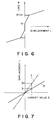
- the spring characteristic of the aforesaid centering spring is made non-linear so that the spring constant of this centering spring is large in a region where the resilient deformation thereof is small whereas the spring constant is small in a region where the resilient deformation is large.
- the four-wheel steering apparatus of the present invention also comprises a front wheel steering angle sensor for detecting the steering angles given to the front wheels, a controller for calculating the steering angles to be given to the rear wheels on the basis of the signals from this front wheel steering angle sensor to output instruction signals in accordance with the result of the calculation thus performed, and an electrically driven actuator for giving the steering angles to the rear wheels in response to the instruction signals.
- a vehicle speed sensor is provided to input the detecting signals from this vehicle speed sensor into the aforesaid controller. Then, the controller stops giving any steering angles to the rear wheels without regard to the detected value of the aforesaid front wheel steering sensor in a case where the vehicle is judged to be at rest on the basis of the signals from the aforesaid vehicle speed sensor, and is characterized by having a function to provide the rear wheels with the steering angles to be calculated on the basis of the signals transmitted from the aforesaid front wheel steering sensor by giving the steering angles to the rear wheels gradually when the vehicle is judged to be in motion again in accordance with the signals from the four-wheel steering sensor after the provision of the steering angles have been once suspended.
- the steering angles are gradually given to the rear wheels when the driving is resumed (the steering angles are not given abruptly as the driving is again started), thus avoiding any sense of incompatibility to be given to the driver.
- An electric four-wheel steering apparatus comprises as in the case of the aforesaid conventional electric four-wheel steering apparatus a front wheel steering angle sensor for detecting the steering angles given to the front wheels, a controller for calculating the steering angles to be given to the rear wheels on the basis of the signals transmitted thereto from the front wheel steering sensor and for outputting the instruction signals in accordance with the result of such calculation, an electric actuator for giving the steering angles to the rear wheels in response to the instruction signals, and a battery for energizing the electric actuator.
- source voltage detecting means for detecting the voltage of the aforesaid battery to input the detected signals by this source voltage detecting means into the aforesaid controller. Then, this controller makes it possible to provide the rear wheels with a large steering angle if the voltage is high according to the signal transmitted from the aforesaid source voltage detecting means, which indicates the voltage of the above-mentioned battery, and to provide the rear wheels only with a small angle when the aforesaid voltage is low. Then, the controller is characterized by having a function to disable the provision of steering angles to the rear wheels when the aforesaid voltage is low.
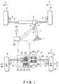
- the operation of the steering wheel 1 provided with facing to the driver's seat is transmitted to a steering gear 3 through a steering shaft 2 to displace the front wheel output shaft 4 in the axial direction (to the left and right directions in Fig. 1), thus giving a desired steering angle to the front wheels 6 and 6 through a pair of the knuckle arms 5 and 5 each on the left and right side connected respectively to the both ends of this front output shaft 4.
- the front wheel steering angle sensors 8 and 8 are supported, and by the rotational angles detected by this front wheel steering angle sensors 8 and 8, the steering angles given to the front wheels 6 and 6 are freely detected.
- the reason why the two front wheel steering sensors 8 and 8 are provided is that even if one of the front wheel steering sensor 8 should be damaged, desired controls are steel possible by the other sensor, thus attaining the fail-safe.
- a housing 10 for accommodating a mechanism for giving steering angles to the rear wheels 9 and 9 is supported in such a manner that any displacement over the width direction of the vehicle (to the left and right directions in Fig. 1 and Fig. 2) is disabled. Then, through the inner side of this housing 10, the rear wheel output shaft 11 penetrates in the left and right directions (width direction of the vehicle). Along with the displacement in the axial direction (the left and right directions), this rear wheel output shaft 11 gives steering angles to the aforesaid rear wheels 9 and 9, and the both ends on the left and right sides of the rear wheel output shaft 11 and each of the rear wheels 9 and 9 are connected through knucle arms 13 and 13.
- each of the rear wheels 9 and 9 is rocked with the steering centers 14 and 14 as the center of rocking so that the steering angle corresponding to the displacement amount of the aforesaid rear wheel output shaft 11 is given to each of the rear wheels 9 and 9.
- the steering centers 14 and 14 of the rear wheels 9 and 9 are positioned backwards (downwards in Fig. 1) in the traveling direction of the vehicle (upwards in Fig. 1) from the points of application force 12 and 12 (the center of contact area between the bottom face and ground) of the aforesaid rear wheels 9 and 9 by a distance 1.
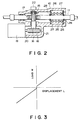
- a rack 15 is fixedly provided in a portion of the intermediate portion of the aforesaid rear wheel output shaft 11 located inside the aforesaid housing 10.
- a pinion 17 is fixedly provided at one end portion (upper end in Fig. 1 and Fig. 2) of the transmission shaft 16 which is rotatively supported in helically positional relationship with the aforesaid rear wheel output shaft 11 in the inner side of the aforesaid housing 10, and this pinion 17 is allowed to engage with the rack 15.
- a worm wheel 18 is fixedly provided at the other end (lower end in Fig. 1 and Fig. 2) of the aforesaid transmission shaft 16.
- a worm 21 is fixedly mounted, and a speed reducing mechanism is constructed by allowing this worm 21 to engage with the worm wheel 18 to displace the aforesaid rear wheel output shaft 11 in the axial direction by the rotation of the aforesaid output shaft 20.
- This speed reducing mechanism should have reversibility in the power transmission direction, and accompanying the rotation of the aforesaid output shaft 20, this mechanism causes not only the rear wheel output shaft to be displaced in the axial direction, but accompanying the displacement of the rear wheel output shaft 11 in the axial direction, it causes the aforesaid output shaft 20 to be rotated.
- the restraining the reversibility factor of the speed reducing mechanism low, the load given by the compression of the centering spring 25 which will be described later is not added to the aforesaid electric motor 19 as it is.
- a displacement sensor 22 is provided to freely detect the displacement amount of the aforesaid rear wheel output shaft 11 through the transmission shaft 16.
- the detecting signals being transmitted from this displacement sensor 22 are inputted into a controller 24 which controls the energizing of the aforesaid electric motor 19 together with the detecting signals from the aforesaid front wheel sensors 8 and 8 as well as the detecting signals from the vehicle speed sensor 23 which detects the speeds of the vehicle.
- the reason why the aforesaid displacement sensor 22 is provided is that when the displacement amount of the rear wheel output shaft 11 should be deviated from a desired value due to a trouble or the like occurring in the aforesaid controller 24, the fail-safe is attained by the function of this sensor.
- the aforesaid rear wheel output shaft 11 is supported with a slight displacing freedom in the axial direction (the left and right directions in Fig. 1 and Fig. 2) and also resiliently with respect to the aforesaid housing 10.
- a pair of washer plates 26 and 26 are attached to the rear wheel output shaft 11 at intervals with fitted thereto as well as with a slight displacing freedom in the axial direction of the aforesaid rear wheel output shaft 11 and at the same time, there is provided between the inner faces of the both washer plates 26 and 26 the centering spring 25 having resiliency strong enough to cause the aforesaid rear wheel output shaft 11 to be returned to the neutral position when the aforesaid electric motor 19 should be in trouble.
- a pair of staged portions 27 and 27 are formed at intervals with each other, and the external peripheral portions of the outer side faces of the aforesaid pair of washer plates 26 and 26 are arranged to face the staged portions 27 and 27 respectively.
- a pair of stop rings 28 and 28 are fixedly provided at positions sandwiching the aforesaid pair of washer plates 26 and 26 on the outer periphery of the intermediate portion of the aforesaid rear wheel output shaft 11 to restrict the movement of the each of the washer plates 26 and 26 with respect to the rear wheel output shaft 11.
- the aforesaid rear wheel output shaft 11 is returned to the neutral position by the resiliency of the aforesaid centering spring 25 unless an outer force such as given by the aforesaid electric motor 19 being energized.
- the aforesaid controller 24 adjusts the output torque of the aforesaid electric motor 19 to a desired value in response to the signals being transmitted from the aforesaid front wheel steering sensors 8 and 8 as well as from the vehicle speed sensor 23, and performs the controlling to displace the aforesaid rear wheel output shaft 11 by open control for the desired value.
- arithmetic processing unit of the aforesaid controller 24 there is incorporated a function capable of adjusting the energizing amount for the electric motor 19 on the basis of the relationship represented in the aforesaid Fig. 4. Then, on the basis of the signals being transmitted from the aforesaid front wheel steering angle sensors 8 and 8 and vehicle speed sensor 23, a desired current is given to the aforesaid electric motor 19 in accordance with the relationship represented in Fig. 4 when it is determined that a steering angle should be given to the aforesaid rear wheels 9 and 9 to displace the aforesaid rear wheel output shaft 11 only by the desired amount.
- the aforesaid controller 24 obtains on the basis of the signals from the front wheel steering angle sensors 8 and 8 and vehicle speed sensor 23 and, further on the basis of the signals, if required, from a lateral acceleration sensor or yaw rate sensor (not shown), the size of the steering angle to be given to the rear wheels 9 and 9 on the basis of the signals from the aforesaid front wheel steering angle sensors 8 and 8 and vehicle speed sensor 23 as well as the displacement amount L of the rear wheel output shaft 11 which is required to obtain the aforesaid steering angle.
- the displacement amount L given to the rear wheel output shaft 11 on the basis of the energizing of the electric motor 19 is detected by the displacement sensor 22 mounted on the end portion of the transmission shaft 16, and is inputted into the aforesaid controller 24.
- the signal from the aforesaid displacement sensor 22 is only used for the so-called fail-safe in determining whether or not the displacement amount L of the rear wheel output shaft 11 has been provided as desired.
- the controller 24 performs the open control which is not related to the signals from the displacement sensor 22 to displace the rear wheel output shaft 11 and does not perform any closed control utilizing the signals from the displacement sensor 22. Therefore, if the reliability of the composite devices is sufficiently high, the aforesaid displacement sensor 22 can be omitted.
- the provision of the steering angles to the rear wheels 9 and 9 on the basis of the energizing of the electric motor 19 as set forth above is executed only when the vehicle is driven at comparatively low speeds (for example, 40 km/h or less) in consideration of safety in a case where the system should be troubled. Then, in the embodiment shown in Fig. 1 and Fig. 2, if the vehicle is driven at speeds exceeding the aforesaid predetermined speed (40 km/h), the controller 24 does not perform any longer the control of the steering angles given to the rear wheels 9 and 9 irrespective of the signals from the front wheel steering sensors 8 and 8 and vehicle speed sensor 23.
- the controller when a vehicle is driven at speeds exceeding a predetermined speeds, the controller will never cause the electric motor 19 to be energized. However, the output shaft 20 of the electric motor 19 is not locked even when the electric motor is not energized, and the shaft is freely rotatable by an external force.
- This force F is given to the contacting area between the rear wheels 9 and 9 and the ground, that is, the perpendicular area including the points of application force 12 and 12 of each of the rear wheels 9 and 9. Meanwhile, since the steering centers 14 and 14 on each of the rear wheels 9 and 9 are positioned backwards in the traveling direction of the vehicle from the aforesaid points of application force 12 and 12 by a distance l, each of the rear wheels 9 and 9 are steered in the direction indicated by arrow ⁇ in Fig. 1 by a moment F ⁇ l.
- the steering angles given to the rear wheels 9 and 9 are always in the same phase as the front wheels 6 and 6. Also, in this case, the size of the steering angles given to the rear wheels 9 and 9 is determined by the strength of the lateral force F added to the rear wheels 9 and 9 resulting from the centrifugal force generated accompanying the changes in the driving lane by the vehicle, and there is no direct relationship (though greatly related indirectly) to the vehicle speeds or the size of the steering angles given to the front wheels 6 and 6.
- the speed reducing mechanism provided between the electric motor 19 and the rear wheel output shaft 11 comprises the worm 21 and worm wheel 18 so that the reverse efficiency is restrained to be low. Consequently, when the steering angles are given to the rear wheels 9 and 9 by the electric motor 19 in driving at low to medium speeds and such condition is kept, any great load to the aforesaid electric motor 19 is not caused to remain as it is because of the working resiliency of the aforesaid centering spring 25.
- the four-wheel steering apparatus of the present invention is structured to operate as set forth above, there are no need for providing any complicated circuitry and hydraulic or pneumatic pipings, making it possible to provide the four-wheel steering apparatus at comparatively low costs.
- the spring characteristic of the aforesaid centering spring is linear (displacement amount and resiliency change linearly) and the resiliency variation of the aforesaid centering spring 25 is also small when the steering angles are given to the rear wheels 9 and 9.
- the so-called open control whereby only the value E of the current given to the aforesaid electric motor 19 is controlled.
- Fig. 5 and Fig. 6 illustrate another embodiment of an electric four-wheel steering apparatus according to the present invention.
- the rear wheel output shaft 11, which gives the steering angles to the rear wheels 9 and 9 (Fig. 1) by displacing it in the axial directions, is supported with a slight freedom of displacement in the axial direction (the left and right directions in Fig. 5) as well as resiliency with respect to the housing 10 supported on the floor face and others of the vehicle.
- a pair of washer plates 26 and 26 are attached to the rear wheel output shaft 11 at intervals with fitted thereto with a freedom of displacement in the axial direction of the rear wheel output shaft 11 and at the same time, a first centering spring 29, having a resiliency just enough to cause the aforesaid rear wheel output shaft 11 to be also returned to the neutral position in a case of the aforesaid electric motor 19 being in trouble, between the inner faces of the both washer plates 26 and 26 themselves.
- the inner circumferences of the aforesaid pair of washer plates 26 and 26 face respectively the staged portions 30 and 30 (by stop springs or the like can be used instead) provided on the outer circumference of the intermediate portion of the aforesaid rear wheel output shaft 11 so that while the distance of both washer plates 26 and 26 can be reduced but should not be expanded over a certain extent. Then, the space between the aforesaid staged portions 30 and 30 are defined so that the aforesaid first centering spring 29 is caused to remain in a state where a certain value of preliminary pressure f1 is given as it is even when the distance between both washer plates 26 and 26 is maximized as shown in Fig. 6.
- a pair of staged portions 27 and 27 are formed at intervales with each other, and a pair of stop rings 28 and 28 are fixedly provided at portions sandwiching the aforesaid pair of washer plates 26 and 26 on the outer periphery of the intermediate portion of the aforesaid rear wheel output shaft 11.
- the second centering springs 31 and 31 which are disc springs respectively are sandwiched between both stop rings 28 and 28 and staged portions 27 and 27, and the aforesaid pair of washer plates 26 and 26.
- the spring constant of these centering springs 31 and 31 is made greater than that of the first centering spring 29.
- the preliminary pressure f1 given by sandwiching the aforesaid first centering spring 29 with the aforesaid pair of washer plates 26 and 26 should be substantially equal to the resiliency F1 (f1 ⁇ F1) occurring to each of the second centering springs 31 and 31 when the second centering springs 31 and 31 are compressed to the maximum.
- a certain preliminary pressure f2 (which is smaller than the preliminary pressure f1 given to the first centering spring 29, ( ⁇ f1) is exerted between the aforesaid pair of washer plates 26 and 26 and staged portions 27 and 27, and stop rings 28 and 28.
- the aforesaid rear wheel output shaft 11 is caused to be returned to the neutral position by the resiliency of the aforesaid first and second centering springs 29 and 31 arranged in series with each other. Both centering springs 29 and 31 are provided with the preliminary pressures to compress the aforesaid pair of stop rings 28 and 28 with certain forces even when the aforesaid rear wheel output shaft 11 is at the neutral position (displacement 0) as shown in Fig. 5. As a result, the aforesaid rear wheel output shaft 11 is held at the neutral position securely and the aforesaid rear wheels 9 and 9 do not fluctuate.
- the electric four-wheel steering apparatus of the present invention is structured and operated as described above and there are no need of providing any complicated circuitry and hydraulic or pneumatic pipings, thus making it possible to perform fine adjustment of the steering angles given to the rear wheels at comparatively low costs without increasing the consumption of electric power unnecessarily.
- An electric four-wheel steering apparatus is provided with front wheel steering sensors 8 and 8 for detecting the steering angles given to the front wheels 6 and 6 as shown in Fig. 1 and 2, a vehicle speed sensor 23 for detecting the vehicle speed, a rear wheel output shaft 11 for giving steering angles to the rear wheels by displacing it in the axial direction, a centering spring 25 having resiliency in the direction that this rear wheel output shaft 11 is returned to the neutral position, an electric motor 19 for causing the aforesaid rear wheel output shaft 11 to be displaced in the axial direction against the resiliency of this centering spring 25, and a controller 24 for controlling the energizing of the aforesaid electric motor 19 on the basis of signals from the aforesaid front wheel steering angle sensors 8 and 8 and vehicle speed sensor 23.
- this controller 24 calculates the target amount of a steering angle to be given to the rear wheels 9 and 9 on the basis of the signals from the aforesaid front wheel steering sensors 8 and 8 and vehicle speed sensor 23 and controls the aforesaid rear wheel output shaft 11 by the open control so that it can be displaced by a desired amount in order to give the steering angle which matches the target amount to the aforesaid rear wheels 9 and 9 by adjusting the output torque of the aforesaid electric motor 19 by adjusting the current i to be given to this electric motor 19, for example.
- a displacement sensor for example, the sensor 22 in Fig. 1 for detecting the displacement amount of the aforesaid rear wheel output shaft 11 is provided and at the same time, the output from this displacement sensor 22 is inputted into the aforesaid controller 24. Then, this controller 24 is provided with a function whereby to compare the output from the displacement sensor 22 and the aforesaid target amount and if there is a difference between these output and target amount, then the required correction value in the direction (positive or negative) to offset such a difference is added with respect to the output torque of this electric motor 19 by decreasing or increasing the current i to be given to the aforesaid electric motor 19.
- the controller 24 obtains the difference with the target amount to add a correction value to the output torque of the electric motor 19, thus making it possible to give the steering angle, which is equal to the target amount, to the rear wheels 9 and 9 irrespective of the aforesaid degradation of the centering spring 25 due to the elapsed time or the changed hysteresis loop.
- the aforesaid controller 24 performs a correction to make the current i given to the electric motor 19 smaller on the basis of the signals from the aforesaid displacement sensor 22.
- the corrected current value i is given to the aforesaid electric motor 19 to perform the provision of the steering angle matching the target amount to the rear wheels 9 and 9.
- a correction such as this is made each time a steering angle is given to the rear wheels 9 and 9. In practice, therefore, there occurs almost no difference which creates any problem in actual use between the steering angle given to the rear wheels 9 and 9 and the target amount.
- the value i of the current to be given to the aforesaid electric motor 19 is corrected so that the provision of the steering angle matching the target amount to the rear wheels 9 and 9 is performed.
- the four-wheel steering apparatus of the present invention is structured to operate as set forth above, there are no need for providing any complicated circuitry and hydraulic or pneumatic pipings, making it possible to provide the four-wheel steering apparatus which is comparatively inexpensive, yet capable of performing the provision of the steering angle as a target amount to the rear wheels.
- Fig. 11 illustrates another embodiment of the electric four-wheel steering apparatus according to the present invention.
- This electric four-wheel steering apparatus operates the provision of the steering angles to the rear wheels by an electric motor only when the driving speed of the vehicle is comparatively low, and when the driving lanes are changed at a high speed driving, the steering angles are given to the rear wheels on the basis of the centrifugal forces; the provision of the steering angles to the rear wheels is performed by the so-called compliance steering mechanism thereon.
- the operation of a steering wheel 101 provided with facing to the driver's seat is transmitted to the steering gear 103 through the steering shaft 102 to displace the front wheel output shaft 104 in the axial direction (the left and right directions in Fig. 11), and a desired steering angle is given to the front wheels 106 and 106 through a pair of left and right knuckle arms 105 and 105 coupled to the both ends of the aforesaid front wheel output shaft 104 respectively.
- the steering angle sensors 108 and 108 are supported to freely detect the steering angles given to the front wheels 106 and 106 by the rotational angles of the steering shaft 102 detected by this steering angle sensors 108 and 108.
- the reason why two steering angle sensors 108 and 108 are provided is that even if one of the steering angle sensors 108 fails, a desired control should be executed by the other sensor thereby implementing the required fail-safe.
- a housing 110 is supported to accommodate the mechanism to give steering angles to the rear wheels 109 and 109 in such a manner that the housing cannot be displaced in the width direction of the vehicle (in the left and right directions in Fig. 11). Then, through the inside of this housing 110 the rear wheel output shaft 111 is provided in the left and right directions (the width direction of the vehicle).
- This rear wheel output shaft 111 provides steering angles for the rear wheels 109 and 109 by displacing itself in the axial direction (the left and right directions in Fig. 11), and each of the rear wheels 109 and 109 and the left and right side ends of the rear wheel output shaft 111 is coupled respectively by the knuckle arms 112 and 112.
- each of the rear wheels 109 and 109 is rocked as each of the steering centers 113 and 113 as its center, so that a steering angle corresponding to the displacement amount of the aforesaid rear wheel output shaft 111 is given to each of the rear wheels 109 and 109.
- the steering centers 113 and 113 of the rear wheels 109 and 109 are positioned backward (downward direction in Fig. 11) from the point of application forces applied 114 and 114 (the center of the contact face between the bottom of tire and the ground) by a distance l in the longitudianl direction (the upward direction in Fig. 11).
- a rack 115 is fixed on the intermediate section of the aforesaid rear wheel shaft 111, which is located in the aforesaid housing 110.
- a pinion gear 117 is fixed to the one end of the transmission shaft 116 (the upper end in Fig. 11) which is rotatively supported in the aforesaid housing 110 with a helically positional relationship to the aforesaid rear wheel output shaft 111, and this pinion gear 117 is arranged to engage with the aforesaid rack 115.
- a worm wheel 118 is fixed on the other end of the aforesaid transmission shaft 116 (the lower end in Fig. 11)
- an electric motor 119 is supportable fixed on the outer face of the aforesaid housing 110. Then a worm 122 is fixed to the output shaft 121 driven by the rotational shaft (not shown) of the electric motor 119 through an electromagnetic clutch 120, and by the engagement of this worm 122 with the aforesaid worm wheel 118, a speed reducing mechanism is constructed to displace the aforesaid rear wheel output shaft 111 in the axial direction by the rotation of the aforesaid output shaft 121.
- This speed reducing mechanism should have the reversibility in the power transmission direction, and accompanying the rotation of the aforesaid output shaft 121, this mechanism not only displaces the rear wheel output shaft 111 in the axial direction but causes the aforesaid output shaft 121 to rotate following the displacement of the rear wheel output shaft 111 in the axial direction.
- this mechanism by restraining the reversibility factor of the aforesaid speed reducing mechanism low so as not to allow the load given by the centering spring 123, which will be described later, to be exerted on the aforesaid motor as it is when the steering angles are given to each of the aforesaid rear wheels 109 and 109.
- a rotational angle sensor 124 is additionally provided to freely detect the rotational amount of the electric motor 119, and this amount is inputted into the controller 125 which will subsequently be described.
- two displacement sensors 126 and 126 are provided to freely detect the displacement amount of the aforesaid rear wheel output shaft 111 through the transmission shaft 116.
- the detection signals transmitted from these two displacement sensors 126 and 126 are inputted into the controller 125 to control the energizing of the aforesaid motor 119 together with the detection signals form the aforesaid front wheel steering angle sensors 108 and 108 and the detection signals from a vehicle velocity sensor 127 for detecting the vehicle speed.
- the reason why two of the aforesaid displacement sensors 126 and 126 are provided is also to implement the fail-safe.
- the aforesaid controller 125 serves to connect the aforesaid electromagnetic clutch 120 only when the vehicle speed detected by the aforesaid vehicle speed sensor 127 is lower than a predetermined value (for example, 40 km/h), and to perform the provision of the steering angle to the rear wheels 109 and 109 by the aforesaid electric motor 119 on the basis of the signals form the aforesaid steering angle sensors 108 and 108 and vehicle speed sensor 127.
- the controller controls the energizing of the aforesaid electric motor 119 on the basis of the signals form the rotational angle sensor 124.
- the displacement sensors 126 and 126 mounted at the one end of the transmission shaft 116 detect the steering angle actually given to the rear wheels 109 and 109 and input the detected value into the aforesaid controller 125.
- the aforesaid rear wheel output shaft 111 is resiliently supported with a slight freedom of displacement in the axial direction with respect to the housing 110 fixed on the vehicle body.
- a pair of washer plates 128 and 128 are fitted from the outside apart from each other on the intermediate section of the aforesaid rear wheel output shaft 111 and supported to be freely displaceable in the axial direction of the rear wheel output shaft 111 and at the same time, there is provided in the space between the inner faces of the washer plates 128 and 128, the centering spring 123 having a resiliency just enough to enable the aforesaid rear wheel shaft 111 to be returned to the neutral position even when the aforesaid electric motor 119 is in trouble.
- a pair of staged portions 129 and 129 are formed at intervals with each other, and the outer circumferential portions of the outer peripheries of the aforesaid pair of washer plates 128 and 128 are arranged to face the staged portions 129 and 129 respectively.
- a pair of stop rings 130 and 130 are fixedly mounted to restrain the shifting of each of the washer plates 128 and 128 with respect to the rear wheel output shaft 111.
- disc springs 131 and 131 are provided between the external faces of the aforesaid pair of washer plates 128 and 128, staged portions 129 and 129, and stop rings 130 and 130.
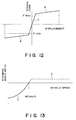
- the resiliency required to flatten the disc springs 131 and 131 completely is smaller than the resiliency when the aforesaid centering spring 123 begins to compressed, and when the rear wheel output shaft 111 is displaced with respect to the housing 110, the disc springs 131 and 131 are first displaced (flattened) as represented by a straight line a in Fig. 12. Then, the arrangement is made so that subsequent to either one of the disc springs 131 (on the leading end side of the displacement direction) having been completely flattened, the aforesaid centering spring 123 begins to be compressed between the pair of the washer plates 128 and 128 as represented by a straight line b in Fig. 12.
- the spring load when each of the disc spring 131 and 131 is completely compressed, is slightly larger than the estimated maximum lateral load F MAX exerted on the rear wheel output shaft 111 on the basis of centrifugal forces generated in the expected driving conditions.
- the controller 125 controls the energizing of the electric motor 119 on the basis of the signals from the front wheel steering angle sensors 108 and 108 and vehicle speed sensor 127 and provides the rear wheels 109 and 109 with desired steering angles as required.
- the electromagnetic clutch 120 is energized so that this electromagnetic clutch 120 remains in its connected condition.
- the steering angles given to the rear wheels 109 and 109 are made smaller as the vehicle speeds become faster as represented by a solid line c in Fig. 13.
- the steering angles given to the rear wheels 109 and 109 are detected by the displacement sensors 126 and 126 mounted at the one end of the transmission shaft 116, and the detected values are inputted into the controller 125 to implement fail-safe.
- the steering angle ratio represented by the axis of ordinate in Fig. 13 is the ratio between a steering angle ⁇ R given to the rear wheels and a steering angle ⁇ F given to the front wheels ( ⁇ R / ⁇ F ), showing that the larger the absolute value is, the greater is the steering angle given to the rear wheels. Also, in the region above the axis of abscissa, the steering angles of the rear and front wheels are in the same phase, and in the region below, in the reverse phase.
- the energizing of the aforesaid electromagnetic clutch 120 is suspended to disconnect the electromagnetic clutch 120.
- the controller 125 is not allowed to control the provision of steering angles to the rear wheels 109 and 109 any more irrespective of the signals from the steering angle sensors 108 and 108 and vehicle speed sensor 127.
- the energizing of the electric motor 119 is suspended, if required.
- the rear wheels 109 and 109 are swung to the right side in Fig. 11 by the centrifugal forces accompanying the changes in the vehicle's driving lanes, and the lateral force F is given to each of the rear wheels 109 and 109 as indicated by arrow ⁇ in Fig. 11 by the friction between the ground and each of the rear wheels 109 and 109.
- This force F is exerted on the contacting faces between the rear wheels 109 and 109 and the ground, i.e., the vertical plane including the point of application force for each of the rear wheels 109 and 109.
- each of the rear wheels 109 and 109 is steered in the direction indicated by arrow ⁇ in the Fig. 11 by a momentum F ⁇ l.
- the steering angles given to the rear wheels 109 and 109 are always in the same phase as those given to the front wheels 106 and 106 as represented by a dashed line d in Fig. 13.
- the size of the steering angles given to the rear wheels 109 and 109 is defined only by the intensity of the lateral force F exerted on the rear wheels 109 and 109 by the centrifugal forces accompanying the changes in the vehicle's driving lanes, and is not directly related to the vehicle speed and the steering angles given to the front wheels 106 and 106 (although indirectly related thereto significantly).
- the allowable range of compression given to the disc springs 131 and 131 is limited. Accordingly, there is no possibility that any excessively large steering angle is given to the rear wheels 109 and 109. Thus, the provision of steerring angles to the rear wheels 109 and 109 by the electric motor 119 is not performed at all when the vehicle travels at high speeds, and only by physical force, the provision of steering angles to the rear wheels 109 and 109 is performed.
- the mechanism for deenergizing the electromagnetic clutch 120 and the electric motor 119 can be a simple one, and it is possible to obtain a sufficient reliability of such mechanism as well as to make the accompanying fail-safe mechanism added to this portion of such mechanism also simple and highly reliable.
- Fig. 9 and Fig. 10 illustrate an example of a controlling conditions when the electric four-wheel apparatus of the present invention performs the provision of steering angles to the rear wheels.
- the electric four-wheel steering apparatus inputs the detected signals from the vehicle speed sensor 127 for detecting the driving speeds of the vehicle into the controller 125 through the conducting line 132 as shown in Fig. 11 as in the case of the aforesaid electric four-wheel steering apparatus.
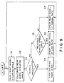
- this controller 125 makes the judgments and instructions as shown in Fig. 9 in order to perform the provisions of steering angles to the rear wheels 109 and 109 (Fig. 11) as shown in Fig. 10, for example, in accordance with changes in the vehicle speed.
- step S1 the detected signals transmitted from the front wheel steering sensors 108 and 108 (Fig. 11) are read into the controller 125. Then, in step S2, the steering angle to be given to the rear wheels 109 and 109 is calculated on the basis of the detected signals, and subsequently, in step S3, the signals form the vehicle speed sensor 127 are examined. If the vehicle speed is judged to be zero, the electrical actuator for the electric motor 119 (Fig. 11) and others are not energized. In other words, as represented in step S4, no steering angles are given to the rear wheels 109 and 109 as far as the vehicle speed is zero.
- step S5 If the vehicle speed is not determined to be zero, whether or not the previous vehicle speed determined before a predetermined time (a second or a period less than that) is examined in step S5.
- the provision of steering angles to the rear wheels 109 and 109 is performed gradually as in the step S6 if the previous vehicle speed is zero.
- the driver does not feel any unnaturalness immediately after the vehicle's driving has begun, and an appropriate provision of the steering angles to the rear wheels 109 and 109 can be performed.
- the steering angles are given to the rear wheels 109 and 109 in amounts corresponding to those given to the front wheels as in the step S7. Then, as the provision of the steering angles to the rear wheels 109 and 109 is performed in synchronization with the operation of the steering wheel 101 (Fig. 11), any unnatural feeling will be given to the driver.
- the aforesaid judgment is performed repeatedly at intervals of the aforesaid predetermined period.
- Fig. 10 shows a state where the provision of the steering angle to the rear wheels 109 and 109 is performed in such a manner that the steering angle given to the front wheels 106 and 106 is being made smaller to make the steering angle to the front wheels 106 and 106 zero at a time T1 and then, at a time T2, the vehicle is brought to a stop, and subsequently, at a time T3, the steering wheel 1 is operated to perform the provision of a steering angle while the vehicle is at reset (the so-called stationary swing), subsequent to which, the vehicle is started at a time T4.
- solid line a indicates the steering angles to be given to the rear wheels 109 and 109 calculated in accordance with the front wheel steering angles in the aforesaid step 2
- broken line b indicates the steering angles actually given to the rear wheels 109 and 109 on the basis of signals from the controller 125, respectively.
- the electric four-wheel steering apparatus of the present invention is applicable to any types of structure if only the steering angles are given to the rear wheels on the basis of the energizing of an electric motor.
- an electric four-wheel steering apparatus to which the present invention is not necessarily of the type having the compliance steering mechanism incorporated as in the case of the aforesaid electric four-wheel steering apparatus.
- the electric four-wheel steering apparatus of the present invention is structured and operated as described above. Therefore, even when the vehicle speed sensor is in trouble or the conductive wiring should be cut, it is possible to secure a highly sound safety by preventing the steering angles in the opposite direction to the front wheels from being given to the rear wheels.
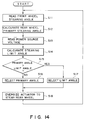
- Fig. 14 shows an example of the controlling state where the electric four-wheel steering apparatus of the present invention performs the provision of steering angles to the rear wheels.
- the electric four-wheel steering apparatus of the present invention detects the voltage of a battery (not shown) by a source voltage detecting means such as a voltmeter (not shown, either) and inputs the detected signals from this source voltage detecting means into a controller 125 (Fig. 11).
- this controller 125 performs the provision of steering angles to the rear wheels 109 and 109 (Fig. 11) in accordance with changes in the vehicle speed by executing the judgments and instructions as shown in Fig. 14.
- step S11 the signals being transmitted from the front wheel steering angle sensors 108 and 108 (Fig. 11) are read to the controller 125.
- step S12 the steering angle (rear wheel primary steering angle) to be given to the rear wheels 109 and 109 is calculated if the battery is assumed to provide a sufficient voltage.
- step S13 the detected signals from the source voltage detecting means are read and in step S14, the maximum value of a steering angle (steering angle limiting value) which can be given to the rear wheels is calculated.
- a load applicable to the battery is considered in accordance with the current voltage of the battery and the aforesaid steering angle limiting value is obtained.
- This steering angle limiting value is defined within the scope where the performance of the battery is not paralyzed even if this limiting steering value should be given to the rear wheels.
- the rear wheel primary steering angle is calculated in step S12, and as the steering angle limiting value is obtained subsequently in step S14 (the order in which the rear wheel primary steering angle and steering angle limiting value may be reversed), the sizes of these rear wheel primary steering angle and steering angle limiting value are examined in step S15 and the smaller value is given to the rear wheels.
- the rear wheel primary steering angle is adopted as a steering angle to be given to the rear wheels as shown in step S16, and if the steering angle limiting value is smaller than the rear wheel primary steering angle, then the steering angle limiting value is adopted as a steering angle to be given to the rear wheels as shown in step S17.
- step S18 the electric actuator is energized to provide the rear wheels with the rear wheel primary steering angle or the steering angle limiting value adopted in the aforesaid step S16 or S17.
- steps S11 through S18 are repeated for each predetermined time (a second or a short period less than a second) in accordance with the signals and others form the pulse oscillator incorporated in the aforesaid controller 125 as far as the vehicle is in traveling.
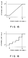
- Fig. 15 and Fig. 16 show the relationship between the battery voltage and the steering limiting value.
- the aforesaid steering angle limiting value is obtained on the basis of the relationship such as shown in Fig. 15 and Fig. 16, and the value thus obtained is transferred to the aforesaid step S15.
- the aforesaid steering angle limiting value is defined as a maximum steering value (7° in the case represented in Fig. 15 and Fig. 16) which can be given to the rear wheels.
- the function of the battery may be paralyzed by energizing the aforesaid electric actuator and the aforesaid steering angle limiting value is made zero so that no provision of steering angles to the rear wheels is performed at all. Then, in a case where the voltage of the battery is between 8 V and 12 V, the aforesaid steering angle limiting value is varied continuously (in the case represented in Fig. 15) or at steps (in the case represented in Fig. 16).
- the electric four-wheel steering apparatus of the present invention is applicable to any types of structure if only the steering angles are given to the rear wheels on the basis of the energizing of an electric motor.
- an electric four-wheel steering apparatus to which the present invention is not necessarily of the type having the compliance steering mechanism incorporated as in the case of the aforesaid electric four-wheel steering apparatus.
- the electric four-wheel steering apparatus of the present invention is structured and operated as described above. Therefore, there is no possibility that the driving of the vehicle is in trouble or the rear wheels remain in such a state that the provision of the steering angle thereto is left intact due to the complete consumption of the battery.
Landscapes
- Engineering & Computer Science (AREA)
- Chemical & Material Sciences (AREA)
- Combustion & Propulsion (AREA)
- Transportation (AREA)
- Mechanical Engineering (AREA)
- Physics & Mathematics (AREA)
- Mathematical Physics (AREA)
- Theoretical Computer Science (AREA)
- Steering-Linkage Mechanisms And Four-Wheel Steering (AREA)
Applications Claiming Priority (10)
| Application Number | Priority Date | Filing Date | Title |
|---|---|---|---|
| JP332191U JPH0495566U (de) | 1991-01-10 | 1991-01-10 | |
| JP3321/91U | 1991-01-10 | ||
| JP62202/91U | 1991-07-12 | ||
| JP6220291U JPH055663U (ja) | 1991-07-12 | 1991-07-12 | 電動式四輪操舵装置 |
| JP6220191U JPH055662U (ja) | 1991-07-12 | 1991-07-12 | 電動式四輪操舵装置 |
| JP62201/91U | 1991-07-12 | ||
| JP1991062469U JP2580083Y2 (ja) | 1991-07-15 | 1991-07-15 | 電動式四輪操舵装置 |
| JP62468/91U | 1991-07-15 | ||
| JP62469/91U | 1991-07-15 | ||
| JP6246891U JPH057577U (ja) | 1991-07-15 | 1991-07-15 | 電動式四輪操舵装置 |
Publications (2)
| Publication Number | Publication Date |
|---|---|
| EP0499027A2 true EP0499027A2 (de) | 1992-08-19 |
| EP0499027A3 EP0499027A3 (en) | 1993-03-17 |
Family
ID=27518343
Family Applications (1)
| Application Number | Title | Priority Date | Filing Date |
|---|---|---|---|
| EP19920100354 Withdrawn EP0499027A3 (en) | 1991-01-10 | 1992-01-10 | Four-wheel steering apparatus |
Country Status (2)
| Country | Link |
|---|---|
| US (1) | US5508921A (de) |
| EP (1) | EP0499027A3 (de) |
Cited By (1)
| Publication number | Priority date | Publication date | Assignee | Title |
|---|---|---|---|---|
| CN1051969C (zh) * | 1992-12-10 | 2000-05-03 | 马自达汽车株式会社 | 用于车辆的四轮操纵系统 |
Families Citing this family (28)
| Publication number | Priority date | Publication date | Assignee | Title |
|---|---|---|---|---|
| KR100231572B1 (ko) * | 1996-04-09 | 1999-12-01 | 류정열 | 자동차의 스티어링 샤프트 각도 감지 센서 |
| DE19716201B4 (de) * | 1997-04-18 | 2012-11-15 | Claas Kgaa Mbh | Mehrachslenkung |
| US6640171B2 (en) * | 1999-12-15 | 2003-10-28 | Delphi Technologies, Inc. | Motor vehicle with supplemental rear steering having open and closed loop modes |
| JP3740970B2 (ja) * | 2000-09-21 | 2006-02-01 | 日産自動車株式会社 | 車両の前後輪舵角制御装置 |
| US6488113B1 (en) * | 2001-06-07 | 2002-12-03 | General Motors Corporation | Disable control for four wheel steer vehicle |
| US6640172B2 (en) * | 2001-08-01 | 2003-10-28 | Delphi Technologies, Inc. | Dual gain algorithm for four wheel steering system |
| US6560524B2 (en) | 2001-09-26 | 2003-05-06 | General Motors Corporation | Integration of rear wheel steering with vehicle stability enhancement system |
| US7401677B2 (en) * | 2002-02-13 | 2008-07-22 | Trw Inc. | Self-centering steering system |
| US6813552B2 (en) | 2002-11-18 | 2004-11-02 | General Motors Corporation | Method and apparatus for vehicle stability enhancement system |
| JP2004170185A (ja) * | 2002-11-19 | 2004-06-17 | Koyo Seiko Co Ltd | 操舵角補正装置 |
| US6865468B2 (en) * | 2002-11-26 | 2005-03-08 | General Motors Corporation | Method and apparatus for vehicle stability enhancement system |
| US6819998B2 (en) * | 2002-11-26 | 2004-11-16 | General Motors Corporation | Method and apparatus for vehicle stability enhancement system |
| US6879898B2 (en) * | 2003-01-03 | 2005-04-12 | General Motors Corporation | Method and apparatus for vehicle integrated chassis control system |
| US6968261B2 (en) * | 2003-01-03 | 2005-11-22 | General Motors Corporation | Method and apparatus for vehicle stability enhancement system |
| US7316288B1 (en) | 2003-01-27 | 2008-01-08 | Polaris Industries Inc. | All terrain vehicle with multiple steering modes |
| US7278511B1 (en) | 2003-01-27 | 2007-10-09 | Polaris Industries Inc. | Controller for steering a vehicle |
| US7073620B2 (en) | 2003-06-06 | 2006-07-11 | Oshkosh Truck Corporation | Vehicle steering system having a rear steering control mechanism |
| US6949901B1 (en) * | 2004-08-30 | 2005-09-27 | Delphi Technologies, Inc. | System and method for controlling a steering position of rear vehicle wheels |
| DE102008026651B4 (de) * | 2007-06-04 | 2020-03-05 | Continental Teves Ag & Co. Ohg | Lenkvorrichtung zum Einstellen eines Radeinschlagwinkels |
| JP4640473B2 (ja) * | 2008-08-21 | 2011-03-02 | トヨタ自動車株式会社 | 車両の操舵装置 |
| JP6252759B2 (ja) * | 2013-08-26 | 2017-12-27 | 株式会社ジェイテクト | 電動パワーステアリング装置 |
| KR102202752B1 (ko) * | 2017-06-30 | 2021-01-14 | 현대모비스 주식회사 | 차량의 후륜 조향 제어 방법 및 장치 |
| JP7192605B2 (ja) * | 2019-03-25 | 2022-12-20 | 株式会社アドヴィックス | 車両の走行制御装置 |
| DE102021201141A1 (de) * | 2021-02-08 | 2022-08-11 | Continental Automotive Gmbh | Regelungseinrichtung und Verfahren zur Lenkwinkelregelung eines Fahrzeugs |
| JP7602956B2 (ja) * | 2021-04-06 | 2024-12-19 | 株式会社ジェイテクト | 操舵制御装置 |
| CN113954956A (zh) * | 2021-11-19 | 2022-01-21 | 扬州动源车用泵业有限公司 | 一种线控主动四轮转向控制装置及其控制方法与控制模式 |
| GB2618548A (en) * | 2022-05-09 | 2023-11-15 | Jaguar Land Rover Ltd | Vehicle controller and control method |
| US20260192852A1 (en) * | 2025-01-06 | 2026-07-09 | GM Global Technology Operations LLC | Active rear steering power consumption management |
Family Cites Families (23)
| Publication number | Priority date | Publication date | Assignee | Title |
|---|---|---|---|---|
| JPS5799470A (en) * | 1980-12-11 | 1982-06-21 | Nissan Motor Co Ltd | Apparatus for controlling compliance steerage |
| JPS58214469A (ja) * | 1982-06-07 | 1983-12-13 | Nissan Motor Co Ltd | 後輪操舵装置 |
| JPS58214470A (ja) * | 1982-06-07 | 1983-12-13 | Nissan Motor Co Ltd | 後輪操舵装置 |
| DE3338702A1 (de) * | 1982-10-28 | 1984-05-03 | Toyo Kogyo Co. Ltd., Hiroshima | Vierrad-lenkung fuer fahrzeuge |
| US4527316A (en) * | 1983-03-21 | 1985-07-09 | Joanne Murphy | Jewelry chain-stay |
| JPS60259571A (ja) * | 1984-06-06 | 1985-12-21 | Mazda Motor Corp | 車両の4輪操舵装置 |
| JPS6175056A (ja) * | 1984-09-17 | 1986-04-17 | Mazda Motor Corp | 車両の4輪操舵装置 |
| JPS63273038A (ja) * | 1987-05-01 | 1988-11-10 | Mazda Motor Corp | 車載制御機器の電源異常検出装置 |
| US4741409A (en) * | 1987-06-25 | 1988-05-03 | General Motors Corporation | Electric steering system for automobiles |
| JPH0696391B2 (ja) * | 1987-11-20 | 1994-11-30 | マツダ株式会社 | 車両の後輪操舵装置 |
| JPH0615342B2 (ja) * | 1988-02-10 | 1994-03-02 | 富士重工業株式会社 | 自動車の後輪操舵装置 |
| DE3807101C1 (de) * | 1988-03-04 | 1989-06-29 | Bayerische Motoren Werke Ag, 8000 Muenchen, De | |
| JP2689335B2 (ja) * | 1988-05-18 | 1997-12-10 | 自動車機器株式会社 | 4輪操舵システム駆動系のセルフチエツク方法 |
| JPH07468B2 (ja) * | 1988-07-04 | 1995-01-11 | マツダ株式会社 | 車両の後輪操舵装置 |
| JPH0218169A (ja) * | 1988-07-05 | 1990-01-22 | Nissan Motor Co Ltd | 4輪操舵車両のフェイルセーフ機構 |
| JP2731917B2 (ja) * | 1988-09-07 | 1998-03-25 | カヤバ工業株式会社 | 後輪操舵装置 |
| FR2639599B1 (fr) * | 1988-11-29 | 1993-09-03 | Renault | Dispositif auxiliaire du traitement des defaillances d'un systeme d'actionnement d'un verin electrique lineaire |
| GB2228460B (en) * | 1988-12-22 | 1993-01-06 | Fuji Heavy Ind Ltd | Rear-wheel steering system for four-wheel steering vehicle |
| JP2514248B2 (ja) * | 1989-05-16 | 1996-07-10 | 日産自動車株式会社 | 車両動特性制御装置 |
| EP0398381B1 (de) * | 1989-05-19 | 1993-12-15 | Nissan Motor Co., Ltd. | Vorrichtung zur Fehlerfeststellung in einem Steuersystem für den Betrieb einer Last |
| JPH0338469A (ja) * | 1989-07-04 | 1991-02-19 | Honda Motor Co Ltd | 前後輪操舵車両における後輪操舵方法 |
| JP2680451B2 (ja) * | 1989-11-22 | 1997-11-19 | 本田技研工業株式会社 | 4輪操舵装置 |
| JPH0764262B2 (ja) * | 1989-11-22 | 1995-07-12 | マツダ株式会社 | 車両の後輪操舵装置 |
-
1992
- 1992-01-10 EP EP19920100354 patent/EP0499027A3/en not_active Withdrawn
-
1995
- 1995-06-07 US US08/470,572 patent/US5508921A/en not_active Expired - Fee Related
Cited By (1)
| Publication number | Priority date | Publication date | Assignee | Title |
|---|---|---|---|---|
| CN1051969C (zh) * | 1992-12-10 | 2000-05-03 | 马自达汽车株式会社 | 用于车辆的四轮操纵系统 |
Also Published As
| Publication number | Publication date |
|---|---|
| EP0499027A3 (en) | 1993-03-17 |
| US5508921A (en) | 1996-04-16 |
Similar Documents
| Publication | Publication Date | Title |
|---|---|---|
| US5508921A (en) | Four wheel steering apparatus | |
| US7322439B2 (en) | Steering apparatus for steerable vehicle | |
| US7065436B2 (en) | Variable ratio steering system | |
| US6213246B1 (en) | Electrically actuated vehicle steering system | |
| US4753310A (en) | Electric power steering device | |
| US7971678B2 (en) | Vehicle steering device and control method for vehicle steering device | |
| US7575092B2 (en) | Vehicle steering control device | |
| EP1325857B1 (de) | Lenksystem mit variabler Übersetzung | |
| US5295550A (en) | Four-wheel steering apparatus | |
| US5487007A (en) | Control system and control method for controlling power steering apparatus | |
| JP3899739B2 (ja) | 車両用操舵装置 | |
| JPS62125907A (ja) | 可変サスペンシヨンジオメトリ装置 | |
| JP3401336B2 (ja) | 車両の操舵補助装置 | |
| JP4680788B2 (ja) | サスペンション装置 | |
| JPH0747991B2 (ja) | 電磁バルブ駆動制御装置 | |
| JPH057577U (ja) | 電動式四輪操舵装置 | |
| JP2580083Y2 (ja) | 電動式四輪操舵装置 | |
| JPH0678069B2 (ja) | ステアリング制御器 | |
| KR100215477B1 (ko) | 변위센서 부착형 유압선형 액튜에이터를 이용한 차량용 능동률 제어장치 | |
| JPH04230472A (ja) | 電子制御パワーステアリング装置 | |
| JPH0825479B2 (ja) | 自動車用後輪操舵装置 | |
| JP2522903Y2 (ja) | 四輪操舵装置 | |
| JPH06278639A (ja) | 車両の制御装置 | |
| JP2004149068A (ja) | 車両用操舵装置 | |
| JP2019151327A (ja) | アクチュエータ制御装置 |
Legal Events
| Date | Code | Title | Description |
|---|---|---|---|
| PUAI | Public reference made under article 153(3) epc to a published international application that has entered the european phase |
Free format text: ORIGINAL CODE: 0009012 |
|
| AK | Designated contracting states |
Kind code of ref document: A2 Designated state(s): DE FR IT |
|
| RIN1 | Information on inventor provided before grant (corrected) |
Inventor name: CHIKUMA, ISAMU Inventor name: KANOU, HIROYUKI Inventor name: KIYONO, KAORU Inventor name: EDA, HIROSHI Inventor name: ANDO, NOBUYASU |
|
| PUAL | Search report despatched |
Free format text: ORIGINAL CODE: 0009013 |
|
| AK | Designated contracting states |
Kind code of ref document: A3 Designated state(s): DE FR IT |
|
| STAA | Information on the status of an ep patent application or granted ep patent |
Free format text: STATUS: THE APPLICATION IS DEEMED TO BE WITHDRAWN |
|
| 18D | Application deemed to be withdrawn |
Effective date: 19930918 |