EP0499097B1 - Antikollisionssicherheitsvorrichtung für Gabelstapler und dergleichen - Google Patents
Antikollisionssicherheitsvorrichtung für Gabelstapler und dergleichen Download PDFInfo
- Publication number
- EP0499097B1 EP0499097B1 EP19920101518 EP92101518A EP0499097B1 EP 0499097 B1 EP0499097 B1 EP 0499097B1 EP 19920101518 EP19920101518 EP 19920101518 EP 92101518 A EP92101518 A EP 92101518A EP 0499097 B1 EP0499097 B1 EP 0499097B1
- Authority
- EP
- European Patent Office
- Prior art keywords
- safety device
- vehicle
- cam
- accordance
- fitted
- Prior art date
- Legal status (The legal status is an assumption and is not a legal conclusion. Google has not performed a legal analysis and makes no representation as to the accuracy of the status listed.)
- Expired - Lifetime
Links
- 230000000284 resting effect Effects 0.000 description 2
- 230000003213 activating effect Effects 0.000 description 1
- 238000010276 construction Methods 0.000 description 1
- 238000010586 diagram Methods 0.000 description 1
- 238000009408 flooring Methods 0.000 description 1
- 230000001105 regulatory effect Effects 0.000 description 1
- 230000011664 signaling Effects 0.000 description 1
Images

Classifications
-
- B—PERFORMING OPERATIONS; TRANSPORTING
- B66—HOISTING; LIFTING; HAULING
- B66F—HOISTING, LIFTING, HAULING OR PUSHING, NOT OTHERWISE PROVIDED FOR, e.g. DEVICES WHICH APPLY A LIFTING OR PUSHING FORCE DIRECTLY TO THE SURFACE OF A LOAD
- B66F17/00—Safety devices, e.g. for limiting or indicating lifting force
- B66F17/003—Safety devices, e.g. for limiting or indicating lifting force for fork-lift trucks
Definitions
- This invention relates to an anti-collision safety device designed in particular for fork-lift trucks and similar vehicles. More specifically, the invention relates to a device consisting of a bar or bumper, fitted to a telescopic support able to traverse and rotate slightly in relation to the truck, which activates suitable alarm and/or stop devices when it collides with an obstacle.
- the invention is characterised by the special configuration of the parts, which is designed to improve and increase the practicality of the safety devices currently fitted to elevators, automatic-drive trucks, etc.
- Safety devices designed to avoid or limit the damage deriving from collisions between the vehicle and an obstacle are already known, being generally fitted to trucks, elevators and vehicles designed for use in factories, construction sites and other workplaces.
- These devices usually consist of bumpers, feelers or the like fitted to the truck which can counteract the force exerted by elastic elements to perform limited movements and which activate an alarm device or stop the movement of the vehicle in the event of a collision.
- US-A-3,023,829 shows a safety device for fork-lift trucks comprising a bumper mounted on a pair of sleeve housings.
- the sleeve housings are secured to the frame of the vehicle and the bumper can slide with respect to each one or both said housings.
- This movements of the bumper with respect to the housings activate means for stopping the vehicle when the movements of the said bumper exceeds a pre-set value.
- FR-A-2 633 571 shows a safety device comprising a bumper mounted on an extensible support and comprising telescopically extensible, rearwards directed wings.
- the invention relates to a safety device for fork-lift trucks, wherein a bumper is mounted on a pair of pistons sliding into corresponding cylinders which can rotate with respect to the chassis of the vehicle, so providing a simple safety apparatus.
- a useful feature would be safety devices designed to detect obstacles at the sides of the truck when it is turning corners.
- this invention proposes an anti-collision safety device for vehicles, in particular fork-lift trucks, which comprises a telescopic support to the front of which is fitted a bumper, preferably also telescopic, which can be extended further forward than the load on the forks and which is connected to the vehicle control equipment.
- This telescopic support can slide and rotate slightly in relation to a pair of guides built into the truck chassis; during these movements it activates a set of microswitches connected to equipment designed to stop the vehicle.
- the safety device assembly in accordance with the invention is indicated by the number 3.
- these devices basically consist of a pair of telescopic supports 4 to the end of which is fitted a bumper 5 equipped with a pair of lateral telescopic arms 6, each of which has the end 7 facing backwards.
- the bumper width and its distance from the truck can therefore be suitably adjusted so that load 8 resting on the forks is surrounded at the front, and the bumper is kept at the most appropriate distance from the load.
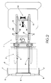
- Telescopic supports 4 comprise a pair of hydraulic cylinders 9, rigidly connected one to another by crosspieces 10, which run inside a pair of guides 11 consisting of two C-sections fixed to the vehicle chassis.
- Each of guides 11 (fig. 3) is fitted with a pair of horizontal-axis rollers 12 and a vertical-axis roller 13, which project slightly from the contour of the guide.
- Cylinders 9 can perform limited movements along guides 11 and, resting against rollers 12 and 13 which keep them at a given distance from the said guides, can also rotate slightly around the point of contact with the rollers.
- the said structure of the telescopic support activates a pair of devices like the one illustrated in fig. 4 and indicated as a whole by the number 14, which are able to activate the vehicle control devices in the event that the bumper collides with an obstacle along the route.
- control devices comprise a shaft 15, built into one of crosspieces 10, for example, along which a pair of cam elements 16, kept apart by a helical spring 17 or the like, can run against a pair of travel limit elements 18 built into the vehicle chassis.
- a pair of adjustable retainers 19 limits the movements of the cams along shaft 15.
- Two microswitches 20 connected to the vehicle control panel or to devices able to stop the vehicle are placed between cam elements 16 and at a distance from them.
- telescopic support 4 is regulated to bring bumper 5 to the desired distance from the load on the forks; the bumper width is also adjusted in relation to the size of both the load and the vehicle.
- the telescopic support assembly retracts or rotates slightly in relation to guides 11 to which it is fitted, moving with it shaft 15 which causes one of cams 16 to engage the corresponding microswitch 20, thereby stopping the movement of the vehicle or signalling the presence of the obstacle to the driver.
- Microswitches 20 will not be placed directly in contact with cams 16 but at a distance from them to prevent the safety devices from being activated, for example, by vibrations transmitted to the structure while the vehicle is moving as a result of uneven flooring and the like.
- the cam device shown in fig. 4 can also be configured differently, for example as illustrated in fig. 5, where a cam element 21, kept mid-way between two fixed supports 23 by a pair of springs 22, can run along shaft 15.
- the cam presents a flat section of a certain length to allow the telescopic support a minimum of free travel without the microswitch's being engaged, to prevent small movements caused by vibrations from activating the device.
Landscapes
- Life Sciences & Earth Sciences (AREA)
- Engineering & Computer Science (AREA)
- Geology (AREA)
- Mechanical Engineering (AREA)
- Structural Engineering (AREA)
- Forklifts And Lifting Vehicles (AREA)
- Vehicle Step Arrangements And Article Storage (AREA)
Claims (6)
- Sicherheitsvorrichtung für Gabelstapler,
umfassend
einen Stoßfänger (5), der an den Kolben eines teleskopartigen Trägers (4) angebracht ist, dessen Zylinder (9) im Fahrzeugchassis untergebracht sind,
dadurch gekennzeichnet,
daß der Stoßfänger sich im Einsatz weiter nach vorne erstreckt als die auf der Gabel befindliche Last, und daß die Zylinder (9) derart im Chassis der Hubgabel untergebracht sind, daß sie bis zu einem begrenzten Ausmaß relativ zu dem Chassis sich verschieben und drehen können, wobei sie mit einer Einrichtung verbunden sind, die dazu ausgelegt ist, Vorrichtungen (14) zu aktivieren, die das Fahrzeug anhalten, wenn die Bewegungen und/oder Verdrehungen der Zylinder einen vorbestimmten Wert überschreiten. - Sicherheitsvorrichtung nach Anspruch 1,
dadurch gekennzeichnet,
daß der teleskopartige Träger (4) aus einem Paar von hydraulischen Kolben besteht, die in Zylindern (9) gleiten, die innerhalb von C-förmigen Führungen (11) angeordnet sind, wobei leerlaufende Rollen (12) in den Führungen angebracht sind, und etwas aus diesen vorstehen, so daß sie die Zylinder in einem geringen Abstand von den Seiten der Führung halten und ermöglichen, daß diese sich bis zu einem begrenzten Ausmaß verschieben und/oder drehen können. - Sicherheitsvorrichtung nach den vorhergehenden Ansprüchen,
wobei der Träger (4) während seiner Bewegungen einen Nocken (16,28) beaufschlagt, der dazu ausgelegt ist, Mikroschalter (20) zu betägigen, die an die Fahrzeugsteuervorrichtungen angeschlossen sind. - Sicherheitsvorrichtung nach Anspruch 3,
wobei der Nocken (16,21) sich frei bis zu einem gewissen Ausmaß bewegen kann, bevor die Mikroschalter (20) beaufschlagt werden. - Sicherheitsvorrichtung nach Anspruch 3 und 4,
wobei die Vorrichtungen (14) einen Schaft (15) aufweisen, an dem ein Paar von Nocken (16), die durch elastische Elemente (17) in einem Abstand voneinander gehalten werden, sich bewegen kann, wobei Wegbegrenzungselemente (18), die mit den Nocken in Eingriff treten, in das Fahrzeugchassis eingebaut sind und Mikroschalter (20), die mit den Fahrzeugsteuereinrichtungen in Verbindung stehen, in dem Abstand zwischen diesen Nocken angeordnet sind. - Sicherheitsvorrichtung nach Anspruch 3 und 4,
dadurch gekennzeichnet,
daß diese Nockeneinrichtungen (14) einen in den teleskopartigen Träger eingebauten Schaft aufweisen, an dem ein mit einem flachen mittigen Abschnitt versehener Nocken (21) angebracht ist, wobei ein Mikrokschalter 20, der mit den Fahrzeugsteuereinrichtungen verbunden ist, mit dem flachen mittigen Abschnitt dieses Nockens (21) in Eingriff tritt, wenn der teleskopartige Träger (4) mit dem Fahrzeug ausgerichtet ist.
Applications Claiming Priority (2)
| Application Number | Priority Date | Filing Date | Title |
|---|---|---|---|
| ITPC910003U | 1991-02-12 | ||
| IT91PC000003U IT225709Y1 (it) | 1991-02-12 | 1991-02-12 | Dispositivo di sicurezza antiurto per carrelli elevatori o simili. |
Publications (3)
| Publication Number | Publication Date |
|---|---|
| EP0499097A2 EP0499097A2 (de) | 1992-08-19 |
| EP0499097A3 EP0499097A3 (en) | 1993-03-10 |
| EP0499097B1 true EP0499097B1 (de) | 1996-11-06 |
Family
ID=11388942
Family Applications (1)
| Application Number | Title | Priority Date | Filing Date |
|---|---|---|---|
| EP19920101518 Expired - Lifetime EP0499097B1 (de) | 1991-02-12 | 1992-01-30 | Antikollisionssicherheitsvorrichtung für Gabelstapler und dergleichen |
Country Status (5)
| Country | Link |
|---|---|
| EP (1) | EP0499097B1 (de) |
| JP (1) | JPH05147482A (de) |
| DE (1) | DE69214971T2 (de) |
| ES (1) | ES2093119T3 (de) |
| IT (1) | IT225709Y1 (de) |
Families Citing this family (6)
| Publication number | Priority date | Publication date | Assignee | Title |
|---|---|---|---|---|
| SE503915C2 (sv) * | 1995-01-27 | 1996-09-30 | Andersson Hakan | Påkörningsskydd |
| CN100360347C (zh) * | 2005-04-12 | 2008-01-09 | 赵铁生 | 可自由伸缩式、缓冲、吸能汽车防撞保险杠 |
| CN102069768A (zh) * | 2009-11-25 | 2011-05-25 | 凌建军 | 一种机动车安全防撞装置及带有该防撞装置的机动车底盘 |
| CN102582550B (zh) * | 2012-02-29 | 2014-10-01 | 长城汽车股份有限公司 | 一种溃缩防撞梁系统 |
| CN104859440A (zh) * | 2015-06-12 | 2015-08-26 | 邓莉莉 | 滑移式agv导航小车 |
| CN114873509A (zh) * | 2022-06-06 | 2022-08-09 | 中科微至科技股份有限公司 | Agv用旋转举升装置 |
Family Cites Families (10)
| Publication number | Priority date | Publication date | Assignee | Title |
|---|---|---|---|---|
| US1922570A (en) * | 1932-04-30 | 1933-08-15 | Shano Ray J De | Automatic safety brake |
| US3023829A (en) * | 1960-06-10 | 1962-03-06 | Brake And Bearing Service Co I | Obstruction operated brake setting mechanism for road vehicle |
| US3744588A (en) * | 1971-12-28 | 1973-07-10 | M Nave | Vehicular brake actuating device |
| FR2499536B1 (fr) * | 1981-02-06 | 1985-07-05 | Constr Telephoniques | Dispositif de protection pour chariot de manutention |
| US4397372A (en) * | 1981-03-09 | 1983-08-09 | Bell & Howell Company | Pendulum suspended bumper assembly |
| DE3213957C2 (de) * | 1982-04-16 | 1987-04-02 | Mannesmann AG, 4000 Düsseldorf | Auffahrabschaltung für ein Fahrzeug |
| US4496274A (en) * | 1982-08-11 | 1985-01-29 | Eaton Corporation | Material handling vehicle |
| CH662992A5 (fr) * | 1985-03-01 | 1987-11-13 | Jd Technologie Ag | Dispositif de protection contre les tamponnements pour vehicules de transport au sol. |
| DE3732724A1 (de) * | 1987-09-29 | 1989-04-13 | Jungheinrich Kg | Sicherheitseinrichtung fuer gabelfahrzeuge |
| FR2633571B1 (fr) * | 1988-06-30 | 1992-01-10 | Axter Sa | Bouclier de protection a deux positions |
-
1991
- 1991-02-12 IT IT91PC000003U patent/IT225709Y1/it active IP Right Grant
-
1992
- 1992-01-30 EP EP19920101518 patent/EP0499097B1/de not_active Expired - Lifetime
- 1992-01-30 ES ES92101518T patent/ES2093119T3/es not_active Expired - Lifetime
- 1992-01-30 DE DE1992614971 patent/DE69214971T2/de not_active Expired - Fee Related
- 1992-02-12 JP JP2488492A patent/JPH05147482A/ja active Pending
Also Published As
| Publication number | Publication date |
|---|---|
| IT225709Y1 (it) | 1997-01-13 |
| JPH05147482A (ja) | 1993-06-15 |
| ITPC910003V0 (it) | 1991-02-12 |
| EP0499097A2 (de) | 1992-08-19 |
| ITPC910003U1 (it) | 1992-08-12 |
| DE69214971T2 (de) | 1997-03-06 |
| DE69214971D1 (de) | 1996-12-12 |
| ES2093119T3 (es) | 1996-12-16 |
| EP0499097A3 (en) | 1993-03-10 |
Similar Documents
| Publication | Publication Date | Title |
|---|---|---|
| US5213383A (en) | Anti-collision safety device for forklift trucks and the like | |
| EP3377274B1 (de) | Ankoppeleinrichtung und ankoppelverfahren | |
| US5064022A (en) | Ladder apparatus and method for large mobile equipment | |
| EP1456061B1 (de) | Unterfahrschutzvorrichtung | |
| US6109675A (en) | Hinged member for a rear impact guard | |
| US4635982A (en) | Collision protection device for industrial vehicles, especially industrial trucks | |
| US7165776B2 (en) | Pivotable tray for a pallet truck | |
| US4763939A (en) | Protective roller device for car | |
| CN112207842A (zh) | 智能安防巡逻机器人 | |
| EP0499097A2 (de) | Antikollisionssicherheitsvorrichtung für Gabelstapler und dergleichen | |
| DE19749900A1 (de) | Fahrerloses, z. B. frei navigierendes Transportfahrzeug zum Handhaben von Lasten | |
| EP1221001B1 (de) | Zahnstange und zahnrad getriebe | |
| DE3732724C2 (de) | ||
| CN211168781U (zh) | 滚床活动挡块机构以及输送设备 | |
| JPH0755793B2 (ja) | 前載式荷物取扱い用トラック | |
| US2931531A (en) | Lift truck attachment | |
| US20080025827A1 (en) | Basket apparatus for mounting wheel to vehicle | |
| CN220842452U (zh) | 一种压缩式垃圾车的侧防护装置 | |
| US5482134A (en) | Anticollision device for driverless industrial trucks | |
| CN214330212U (zh) | 一种公路工程施工用道路防护装置 | |
| CN215798328U (zh) | 曲臂车防撞设施 | |
| US3899935A (en) | Transmission control apparatus for a vehicle or the like | |
| US5368331A (en) | Safety steering wheel device for a motor car | |
| KR101262209B1 (ko) | 안전장치를 가지는 운반차 | |
| KR940007724Y1 (ko) | 코일카(Coil Car)의 코일전도 방지장치 |
Legal Events
| Date | Code | Title | Description |
|---|---|---|---|
| PUAI | Public reference made under article 153(3) epc to a published international application that has entered the european phase |
Free format text: ORIGINAL CODE: 0009012 |
|
| AK | Designated contracting states |
Kind code of ref document: A2 Designated state(s): DE ES FR GB |
|
| PUAL | Search report despatched |
Free format text: ORIGINAL CODE: 0009013 |
|
| AK | Designated contracting states |
Kind code of ref document: A3 Designated state(s): DE ES FR GB |
|
| 17P | Request for examination filed |
Effective date: 19930723 |
|
| D17P | Request for examination filed (deleted) | ||
| R17P | Request for examination filed (corrected) |
Effective date: 19930727 |
|
| 17Q | First examination report despatched |
Effective date: 19950222 |
|
| GRAH | Despatch of communication of intention to grant a patent |
Free format text: ORIGINAL CODE: EPIDOS IGRA |
|
| GRAH | Despatch of communication of intention to grant a patent |
Free format text: ORIGINAL CODE: EPIDOS IGRA |
|
| GRAA | (expected) grant |
Free format text: ORIGINAL CODE: 0009210 |
|
| AK | Designated contracting states |
Kind code of ref document: B1 Designated state(s): DE ES FR GB |
|
| REF | Corresponds to: |
Ref document number: 69214971 Country of ref document: DE Date of ref document: 19961212 |
|
| REG | Reference to a national code |
Ref country code: ES Ref legal event code: FG2A Ref document number: 2093119 Country of ref document: ES Kind code of ref document: T3 |
|
| ET | Fr: translation filed | ||
| PLBE | No opposition filed within time limit |
Free format text: ORIGINAL CODE: 0009261 |
|
| STAA | Information on the status of an ep patent application or granted ep patent |
Free format text: STATUS: NO OPPOSITION FILED WITHIN TIME LIMIT |
|
| 26N | No opposition filed | ||
| PGFP | Annual fee paid to national office [announced via postgrant information from national office to epo] |
Ref country code: GB Payment date: 19971030 Year of fee payment: 7 |
|
| PGFP | Annual fee paid to national office [announced via postgrant information from national office to epo] |
Ref country code: FR Payment date: 19971031 Year of fee payment: 7 |
|
| PGFP | Annual fee paid to national office [announced via postgrant information from national office to epo] |
Ref country code: ES Payment date: 19980102 Year of fee payment: 7 |
|
| PGFP | Annual fee paid to national office [announced via postgrant information from national office to epo] |
Ref country code: DE Payment date: 19980227 Year of fee payment: 7 |
|
| PG25 | Lapsed in a contracting state [announced via postgrant information from national office to epo] |
Ref country code: GB Free format text: LAPSE BECAUSE OF NON-PAYMENT OF DUE FEES Effective date: 19990130 |
|
| PG25 | Lapsed in a contracting state [announced via postgrant information from national office to epo] |
Ref country code: ES Free format text: LAPSE BECAUSE OF NON-PAYMENT OF DUE FEES Effective date: 19990201 |
|
| GBPC | Gb: european patent ceased through non-payment of renewal fee |
Effective date: 19990130 |
|
| PG25 | Lapsed in a contracting state [announced via postgrant information from national office to epo] |
Ref country code: FR Free format text: LAPSE BECAUSE OF NON-PAYMENT OF DUE FEES Effective date: 19990930 |
|
| PG25 | Lapsed in a contracting state [announced via postgrant information from national office to epo] |
Ref country code: DE Free format text: LAPSE BECAUSE OF NON-PAYMENT OF DUE FEES Effective date: 19991103 |
|
| REG | Reference to a national code |
Ref country code: FR Ref legal event code: ST |
|
| REG | Reference to a national code |
Ref country code: ES Ref legal event code: FD2A Effective date: 20010503 |