EP0499159B1 - Flüssigkristallvorrichtung und Anzeigevorrichtung - Google Patents
Flüssigkristallvorrichtung und Anzeigevorrichtung Download PDFInfo
- Publication number
- EP0499159B1 EP0499159B1 EP92102070A EP92102070A EP0499159B1 EP 0499159 B1 EP0499159 B1 EP 0499159B1 EP 92102070 A EP92102070 A EP 92102070A EP 92102070 A EP92102070 A EP 92102070A EP 0499159 B1 EP0499159 B1 EP 0499159B1
- Authority
- EP
- European Patent Office
- Prior art keywords
- liquid crystal
- alignment
- substrates
- phenyl
- para
- Prior art date
- Legal status (The legal status is an assumption and is not a legal conclusion. Google has not performed a legal analysis and makes no representation as to the accuracy of the status listed.)
- Expired - Lifetime
Links
- 239000004973 liquid crystal related substance Substances 0.000 title claims abstract description 94
- 239000000758 substrate Substances 0.000 claims abstract description 35
- 239000004990 Smectic liquid crystal Substances 0.000 claims abstract description 31
- 239000002253 acid Substances 0.000 claims abstract description 19
- 150000004985 diamines Chemical class 0.000 claims abstract description 19
- 239000004952 Polyamide Substances 0.000 claims abstract description 13
- 229920002647 polyamide Polymers 0.000 claims abstract description 13
- MZYHMUONCNKCHE-UHFFFAOYSA-N naphthalene-1,2,3,4-tetracarboxylic acid Chemical compound C1=CC=CC2=C(C(O)=O)C(C(=O)O)=C(C(O)=O)C(C(O)=O)=C21 MZYHMUONCNKCHE-UHFFFAOYSA-N 0.000 claims abstract description 9
- 239000007795 chemical reaction product Substances 0.000 claims abstract description 4
- 238000007363 ring formation reaction Methods 0.000 claims abstract description 4
- 229920001721 polyimide Polymers 0.000 claims description 23
- 239000004642 Polyimide Substances 0.000 claims description 14
- GTDPSWPPOUPBNX-UHFFFAOYSA-N ac1mqpva Chemical compound CC12C(=O)OC(=O)C1(C)C1(C)C2(C)C(=O)OC1=O GTDPSWPPOUPBNX-UHFFFAOYSA-N 0.000 claims description 12
- 125000003277 amino group Chemical group 0.000 claims description 8
- 229910052731 fluorine Inorganic materials 0.000 claims description 6
- 125000005647 linker group Chemical group 0.000 claims description 6
- 150000000000 tetracarboxylic acids Chemical class 0.000 claims description 4
- YTVNOVQHSGMMOV-UHFFFAOYSA-N naphthalenetetracarboxylic dianhydride Chemical compound C1=CC(C(=O)OC2=O)=C3C2=CC=C2C(=O)OC(=O)C1=C32 YTVNOVQHSGMMOV-UHFFFAOYSA-N 0.000 claims description 3
- DOBFTMLCEYUAQC-UHFFFAOYSA-N naphthalene-2,3,6,7-tetracarboxylic acid Chemical compound OC(=O)C1=C(C(O)=O)C=C2C=C(C(O)=O)C(C(=O)O)=CC2=C1 DOBFTMLCEYUAQC-UHFFFAOYSA-N 0.000 claims description 2
- 230000001154 acute effect Effects 0.000 claims 1
- IPZJQDSFZGZEOY-UHFFFAOYSA-N dimethylmethylene Chemical compound C[C]C IPZJQDSFZGZEOY-UHFFFAOYSA-N 0.000 claims 1
- 125000001424 substituent group Chemical group 0.000 claims 1
- 206010047571 Visual impairment Diseases 0.000 abstract description 14
- 239000000047 product Substances 0.000 abstract description 4
- 230000004043 responsiveness Effects 0.000 abstract description 3
- 230000005684 electric field Effects 0.000 description 29
- -1 3,3',4,4'-tetracarboxybiphenyl dianhydride Chemical compound 0.000 description 24
- 239000005262 ferroelectric liquid crystals (FLCs) Substances 0.000 description 22
- 125000001997 phenyl group Chemical group [H]C1=C([H])C([H])=C(*)C([H])=C1[H] 0.000 description 22
- 230000003287 optical effect Effects 0.000 description 18
- 239000010410 layer Substances 0.000 description 16
- 210000004027 cell Anatomy 0.000 description 15
- 230000004044 response Effects 0.000 description 15
- SECXISVLQFMRJM-UHFFFAOYSA-N N-Methylpyrrolidone Chemical compound CN1CCCC1=O SECXISVLQFMRJM-UHFFFAOYSA-N 0.000 description 12
- 210000002858 crystal cell Anatomy 0.000 description 11
- ATUOYWHBWRKTHZ-UHFFFAOYSA-N Propane Chemical compound CCC ATUOYWHBWRKTHZ-UHFFFAOYSA-N 0.000 description 10
- 230000002441 reversible effect Effects 0.000 description 10
- 238000002834 transmittance Methods 0.000 description 9
- 230000007704 transition Effects 0.000 description 8
- 230000008859 change Effects 0.000 description 7
- 238000006243 chemical reaction Methods 0.000 description 7
- 239000011521 glass Substances 0.000 description 7
- 239000000463 material Substances 0.000 description 7
- 239000000203 mixture Substances 0.000 description 7
- XEKOWRVHYACXOJ-UHFFFAOYSA-N Ethyl acetate Chemical compound CCOC(C)=O XEKOWRVHYACXOJ-UHFFFAOYSA-N 0.000 description 6
- ZMXDDKWLCZADIW-UHFFFAOYSA-N N,N-Dimethylformamide Chemical compound CN(C)C=O ZMXDDKWLCZADIW-UHFFFAOYSA-N 0.000 description 6
- YXFVVABEGXRONW-UHFFFAOYSA-N Toluene Chemical compound CC1=CC=CC=C1 YXFVVABEGXRONW-UHFFFAOYSA-N 0.000 description 6
- 230000015572 biosynthetic process Effects 0.000 description 6
- 239000001294 propane Substances 0.000 description 6
- 238000009826 distribution Methods 0.000 description 5
- 238000003786 synthesis reaction Methods 0.000 description 5
- OKTJSMMVPCPJKN-UHFFFAOYSA-N Carbon Chemical compound [C] OKTJSMMVPCPJKN-UHFFFAOYSA-N 0.000 description 4
- VYPSYNLAJGMNEJ-UHFFFAOYSA-N Silicium dioxide Chemical compound O=[Si]=O VYPSYNLAJGMNEJ-UHFFFAOYSA-N 0.000 description 4
- 230000008901 benefit Effects 0.000 description 4
- 230000003098 cholesteric effect Effects 0.000 description 4
- 238000000034 method Methods 0.000 description 4
- 230000010287 polarization Effects 0.000 description 4
- 239000002243 precursor Substances 0.000 description 4
- 230000002269 spontaneous effect Effects 0.000 description 4
- XLYOFNOQVPJJNP-UHFFFAOYSA-N water Substances O XLYOFNOQVPJJNP-UHFFFAOYSA-N 0.000 description 4
- PDYQWKUIJVOAON-UHFFFAOYSA-N 4-[4-[2-[4-[4-amino-3-(trifluoromethyl)phenoxy]phenyl]-1,1,1,3,3,3-hexafluoropropan-2-yl]phenoxy]-2-(trifluoromethyl)aniline Chemical compound C1=C(C(F)(F)F)C(N)=CC=C1OC1=CC=C(C(C=2C=CC(OC=3C=C(C(N)=CC=3)C(F)(F)F)=CC=2)(C(F)(F)F)C(F)(F)F)C=C1 PDYQWKUIJVOAON-UHFFFAOYSA-N 0.000 description 3
- 230000008033 biological extinction Effects 0.000 description 3
- 239000011248 coating agent Substances 0.000 description 3
- 238000000576 coating method Methods 0.000 description 3
- 238000004891 communication Methods 0.000 description 3
- 238000010586 diagram Methods 0.000 description 3
- 238000002474 experimental method Methods 0.000 description 3
- 230000006870 function Effects 0.000 description 3
- 238000005227 gel permeation chromatography Methods 0.000 description 3
- VLKZOEOYAKHREP-UHFFFAOYSA-N n-Hexane Chemical compound CCCCCC VLKZOEOYAKHREP-UHFFFAOYSA-N 0.000 description 3
- 239000002904 solvent Substances 0.000 description 3
- 0 *C(CC(CC1)N)(*2CNCC2)/C=C/C1N Chemical compound *C(CC(CC1)N)(*2CNCC2)/C=C/C1N 0.000 description 2
- POAOYUHQDCAZBD-UHFFFAOYSA-N 2-butoxyethanol Chemical compound CCCCOCCO POAOYUHQDCAZBD-UHFFFAOYSA-N 0.000 description 2
- RTZKZFJDLAIYFH-UHFFFAOYSA-N Diethyl ether Chemical compound CCOCC RTZKZFJDLAIYFH-UHFFFAOYSA-N 0.000 description 2
- IAZDPXIOMUYVGZ-UHFFFAOYSA-N Dimethylsulphoxide Chemical compound CS(C)=O IAZDPXIOMUYVGZ-UHFFFAOYSA-N 0.000 description 2
- LFQSCWFLJHTTHZ-UHFFFAOYSA-N Ethanol Chemical compound CCO LFQSCWFLJHTTHZ-UHFFFAOYSA-N 0.000 description 2
- 239000004988 Nematic liquid crystal Substances 0.000 description 2
- CDBYLPFSWZWCQE-UHFFFAOYSA-L Sodium Carbonate Chemical compound [Na+].[Na+].[O-]C([O-])=O CDBYLPFSWZWCQE-UHFFFAOYSA-L 0.000 description 2
- PMZURENOXWZQFD-UHFFFAOYSA-L Sodium Sulfate Chemical compound [Na+].[Na+].[O-]S([O-])(=O)=O PMZURENOXWZQFD-UHFFFAOYSA-L 0.000 description 2
- GWEVSGVZZGPLCZ-UHFFFAOYSA-N Titan oxide Chemical compound O=[Ti]=O GWEVSGVZZGPLCZ-UHFFFAOYSA-N 0.000 description 2
- 150000007513 acids Chemical class 0.000 description 2
- PNEYBMLMFCGWSK-UHFFFAOYSA-N aluminium oxide Inorganic materials [O-2].[O-2].[O-2].[Al+3].[Al+3] PNEYBMLMFCGWSK-UHFFFAOYSA-N 0.000 description 2
- 239000011324 bead Substances 0.000 description 2
- 230000000052 comparative effect Effects 0.000 description 2
- 230000007547 defect Effects 0.000 description 2
- 239000000539 dimer Substances 0.000 description 2
- 239000003480 eluent Substances 0.000 description 2
- 239000004744 fabric Substances 0.000 description 2
- 238000001914 filtration Methods 0.000 description 2
- 238000010438 heat treatment Methods 0.000 description 2
- IKDUDTNKRLTJSI-UHFFFAOYSA-N hydrazine hydrate Chemical compound O.NN IKDUDTNKRLTJSI-UHFFFAOYSA-N 0.000 description 2
- PJXISJQVUVHSOJ-UHFFFAOYSA-N indium(III) oxide Inorganic materials [O-2].[O-2].[O-2].[In+3].[In+3] PJXISJQVUVHSOJ-UHFFFAOYSA-N 0.000 description 2
- AMGQUBHHOARCQH-UHFFFAOYSA-N indium;oxotin Chemical compound [In].[Sn]=O AMGQUBHHOARCQH-UHFFFAOYSA-N 0.000 description 2
- 238000004519 manufacturing process Methods 0.000 description 2
- 239000002052 molecular layer Substances 0.000 description 2
- 238000006116 polymerization reaction Methods 0.000 description 2
- 230000000717 retained effect Effects 0.000 description 2
- 238000010898 silica gel chromatography Methods 0.000 description 2
- 239000000377 silicon dioxide Substances 0.000 description 2
- XOLBLPGZBRYERU-UHFFFAOYSA-N tin dioxide Chemical compound O=[Sn]=O XOLBLPGZBRYERU-UHFFFAOYSA-N 0.000 description 2
- 239000013638 trimer Substances 0.000 description 2
- WZCQRUWWHSTZEM-UHFFFAOYSA-N 1,3-phenylenediamine Chemical compound NC1=CC=CC(N)=C1 WZCQRUWWHSTZEM-UHFFFAOYSA-N 0.000 description 1
- CBCKQZAAMUWICA-UHFFFAOYSA-N 1,4-phenylenediamine Chemical compound NC1=CC=C(N)C=C1 CBCKQZAAMUWICA-UHFFFAOYSA-N 0.000 description 1
- NUIURNJTPRWVAP-UHFFFAOYSA-N 3,3'-Dimethylbenzidine Chemical compound C1=C(N)C(C)=CC(C=2C=C(C)C(N)=CC=2)=C1 NUIURNJTPRWVAP-UHFFFAOYSA-N 0.000 description 1
- JXMTULYAQORCGH-UHFFFAOYSA-N 3-(3,4-dicarboxybenzoyl)phthalic acid Chemical compound C1=C(C(O)=O)C(C(=O)O)=CC=C1C(=O)C1=CC=CC(C(O)=O)=C1C(O)=O JXMTULYAQORCGH-UHFFFAOYSA-N 0.000 description 1
- LXJLFVRAWOOQDR-UHFFFAOYSA-N 3-(3-aminophenoxy)aniline Chemical compound NC1=CC=CC(OC=2C=C(N)C=CC=2)=C1 LXJLFVRAWOOQDR-UHFFFAOYSA-N 0.000 description 1
- LJGHYPLBDBRCRZ-UHFFFAOYSA-N 3-(3-aminophenyl)sulfonylaniline Chemical compound NC1=CC=CC(S(=O)(=O)C=2C=C(N)C=CC=2)=C1 LJGHYPLBDBRCRZ-UHFFFAOYSA-N 0.000 description 1
- CKOFBUUFHALZGK-UHFFFAOYSA-N 3-[(3-aminophenyl)methyl]aniline Chemical compound NC1=CC=CC(CC=2C=C(N)C=CC=2)=C1 CKOFBUUFHALZGK-UHFFFAOYSA-N 0.000 description 1
- UVUCUHVQYAPMEU-UHFFFAOYSA-N 3-[2-(3-aminophenyl)-1,1,1,3,3,3-hexafluoropropan-2-yl]aniline Chemical compound NC1=CC=CC(C(C=2C=C(N)C=CC=2)(C(F)(F)F)C(F)(F)F)=C1 UVUCUHVQYAPMEU-UHFFFAOYSA-N 0.000 description 1
- DVXYMCJCMDTSQA-UHFFFAOYSA-N 3-[2-(3-aminophenyl)propan-2-yl]aniline Chemical compound C=1C=CC(N)=CC=1C(C)(C)C1=CC=CC(N)=C1 DVXYMCJCMDTSQA-UHFFFAOYSA-N 0.000 description 1
- HZTSBUOUMPJHAP-UHFFFAOYSA-N 3-[2-[2-[2-(4-aminophenoxy)phenyl]-1,1,1,3,3,3-hexafluoropropan-2-yl]phenoxy]aniline Chemical compound C1=CC(N)=CC=C1OC1=CC=CC=C1C(C(F)(F)F)(C(F)(F)F)C1=CC=CC=C1OC1=CC=CC(N)=C1 HZTSBUOUMPJHAP-UHFFFAOYSA-N 0.000 description 1
- LBPVOEHZEWAJKQ-UHFFFAOYSA-N 3-[4-(3-aminophenoxy)phenoxy]aniline Chemical compound NC1=CC=CC(OC=2C=CC(OC=3C=C(N)C=CC=3)=CC=2)=C1 LBPVOEHZEWAJKQ-UHFFFAOYSA-N 0.000 description 1
- WECDUOXQLAIPQW-UHFFFAOYSA-N 4,4'-Methylene bis(2-methylaniline) Chemical compound C1=C(N)C(C)=CC(CC=2C=C(C)C(N)=CC=2)=C1 WECDUOXQLAIPQW-UHFFFAOYSA-N 0.000 description 1
- YBRVSVVVWCFQMG-UHFFFAOYSA-N 4,4'-diaminodiphenylmethane Chemical compound C1=CC(N)=CC=C1CC1=CC=C(N)C=C1 YBRVSVVVWCFQMG-UHFFFAOYSA-N 0.000 description 1
- LFBALUPVVFCEPA-UHFFFAOYSA-N 4-(3,4-dicarboxyphenyl)phthalic acid Chemical group C1=C(C(O)=O)C(C(=O)O)=CC=C1C1=CC=C(C(O)=O)C(C(O)=O)=C1 LFBALUPVVFCEPA-UHFFFAOYSA-N 0.000 description 1
- HLBLWEWZXPIGSM-UHFFFAOYSA-N 4-Aminophenyl ether Chemical compound C1=CC(N)=CC=C1OC1=CC=C(N)C=C1 HLBLWEWZXPIGSM-UHFFFAOYSA-N 0.000 description 1
- XGTMNNPOBXQFDN-UHFFFAOYSA-N 4-[2-(1-aminocyclohexa-2,4-dien-1-yl)phenyl]aniline Chemical group NC1(CC=CC=C1)C=1C(=CC=CC=1)C1=CC=C(C=C1)N XGTMNNPOBXQFDN-UHFFFAOYSA-N 0.000 description 1
- APXJLYIVOFARRM-UHFFFAOYSA-N 4-[2-(3,4-dicarboxyphenyl)-1,1,1,3,3,3-hexafluoropropan-2-yl]phthalic acid Chemical compound C1=C(C(O)=O)C(C(=O)O)=CC=C1C(C(F)(F)F)(C(F)(F)F)C1=CC=C(C(O)=O)C(C(O)=O)=C1 APXJLYIVOFARRM-UHFFFAOYSA-N 0.000 description 1
- GEYAGBVEAJGCFB-UHFFFAOYSA-N 4-[2-(3,4-dicarboxyphenyl)propan-2-yl]phthalic acid Chemical compound C=1C=C(C(O)=O)C(C(O)=O)=CC=1C(C)(C)C1=CC=C(C(O)=O)C(C(O)=O)=C1 GEYAGBVEAJGCFB-UHFFFAOYSA-N 0.000 description 1
- BEKFRNOZJSYWKZ-UHFFFAOYSA-N 4-[2-(4-aminophenyl)-1,1,1,3,3,3-hexafluoropropan-2-yl]aniline Chemical compound C1=CC(N)=CC=C1C(C(F)(F)F)(C(F)(F)F)C1=CC=C(N)C=C1 BEKFRNOZJSYWKZ-UHFFFAOYSA-N 0.000 description 1
- ZYEDGEXYGKWJPB-UHFFFAOYSA-N 4-[2-(4-aminophenyl)propan-2-yl]aniline Chemical compound C=1C=C(N)C=CC=1C(C)(C)C1=CC=C(N)C=C1 ZYEDGEXYGKWJPB-UHFFFAOYSA-N 0.000 description 1
- MDMHOHZPQDVCGR-UHFFFAOYSA-N 4-[2-[2-[2-(3-aminophenoxy)phenyl]-1,1,1,3,3,3-hexafluoropropan-2-yl]phenoxy]-3-fluoroaniline Chemical compound NC1=CC=CC(OC=2C(=CC=CC=2)C(C=2C(=CC=CC=2)OC=2C(=CC(N)=CC=2)F)(C(F)(F)F)C(F)(F)F)=C1 MDMHOHZPQDVCGR-UHFFFAOYSA-N 0.000 description 1
- ZNYWGEOLALWSCL-UHFFFAOYSA-N 4-[2-[2-[2-(3-aminophenoxy)phenyl]propan-2-yl]phenoxy]-2-(trifluoromethyl)aniline Chemical compound C=1C=CC=C(OC=2C=C(C(N)=CC=2)C(F)(F)F)C=1C(C)(C)C1=CC=CC=C1OC1=CC=CC(N)=C1 ZNYWGEOLALWSCL-UHFFFAOYSA-N 0.000 description 1
- OHTMZWPFSVFYFL-UHFFFAOYSA-N 4-[2-[2-[2-(4-amino-2-fluorophenoxy)phenyl]-1,1,1,3,3,3-hexafluoropropan-2-yl]phenoxy]-3-fluoroaniline Chemical compound FC1=CC(N)=CC=C1OC1=CC=CC=C1C(C(F)(F)F)(C(F)(F)F)C1=CC=CC=C1OC1=CC=C(N)C=C1F OHTMZWPFSVFYFL-UHFFFAOYSA-N 0.000 description 1
- DRTJVXPSVACTJW-UHFFFAOYSA-N 4-[2-[2-[2-(4-amino-2-fluorophenoxy)phenyl]propan-2-yl]phenoxy]-3-fluoroaniline Chemical compound C=1C=CC=C(OC=2C(=CC(N)=CC=2)F)C=1C(C)(C)C1=CC=CC=C1OC1=CC=C(N)C=C1F DRTJVXPSVACTJW-UHFFFAOYSA-N 0.000 description 1
- ILUFRIWGYBSITQ-UHFFFAOYSA-N 4-[2-[2-[2-(4-amino-2-methylphenoxy)phenyl]-1,1,1,3,3,3-hexafluoropropan-2-yl]phenoxy]-3-methylaniline Chemical compound CC1=CC(N)=CC=C1OC1=CC=CC=C1C(C(F)(F)F)(C(F)(F)F)C1=CC=CC=C1OC1=CC=C(N)C=C1C ILUFRIWGYBSITQ-UHFFFAOYSA-N 0.000 description 1
- SIKVULBGRPCWOD-UHFFFAOYSA-N 4-[2-[2-[2-(4-amino-2-methylphenoxy)phenyl]propan-2-yl]phenoxy]-3-methylaniline Chemical compound CC1=CC(N)=CC=C1OC1=CC=CC=C1C(C)(C)C1=CC=CC=C1OC1=CC=C(N)C=C1C SIKVULBGRPCWOD-UHFFFAOYSA-N 0.000 description 1
- GYUSZGDWOJRSMI-UHFFFAOYSA-N 4-[2-[2-[2-(4-amino-3-fluorophenoxy)phenyl]propan-2-yl]phenoxy]-2-fluoroaniline Chemical compound C=1C=CC=C(OC=2C=C(F)C(N)=CC=2)C=1C(C)(C)C1=CC=CC=C1OC1=CC=C(N)C(F)=C1 GYUSZGDWOJRSMI-UHFFFAOYSA-N 0.000 description 1
- XVWNHMBPYJXFSE-UHFFFAOYSA-N 4-[2-[2-[2-(4-amino-3-methylphenoxy)phenyl]-1,1,1,3,3,3-hexafluoropropan-2-yl]phenoxy]-2-methylaniline Chemical compound C1=C(N)C(C)=CC(OC=2C(=CC=CC=2)C(C=2C(=CC=CC=2)OC=2C=C(C)C(N)=CC=2)(C(F)(F)F)C(F)(F)F)=C1 XVWNHMBPYJXFSE-UHFFFAOYSA-N 0.000 description 1
- BMRWXYLZMCGJQL-UHFFFAOYSA-N 4-[2-[2-[2-(4-aminophenoxy)phenyl]-1,1,1,3,3,3-hexafluoropropan-2-yl]phenoxy]-2-fluoroaniline Chemical compound C1=CC(N)=CC=C1OC1=CC=CC=C1C(C(F)(F)F)(C(F)(F)F)C1=CC=CC=C1OC1=CC=C(N)C(F)=C1 BMRWXYLZMCGJQL-UHFFFAOYSA-N 0.000 description 1
- YPGXCJNQPKHBLH-UHFFFAOYSA-N 4-[2-[2-[2-(4-aminophenoxy)phenyl]-1,1,1,3,3,3-hexafluoropropan-2-yl]phenoxy]aniline Chemical compound C1=CC(N)=CC=C1OC1=CC=CC=C1C(C(F)(F)F)(C(F)(F)F)C1=CC=CC=C1OC1=CC=C(N)C=C1 YPGXCJNQPKHBLH-UHFFFAOYSA-N 0.000 description 1
- NLJYIVZDFZOJTC-UHFFFAOYSA-N 4-[2-[2-[2-(4-aminophenoxy)phenyl]propan-2-yl]phenoxy]-2-(trifluoromethyl)aniline Chemical compound C=1C=CC=C(OC=2C=C(C(N)=CC=2)C(F)(F)F)C=1C(C)(C)C1=CC=CC=C1OC1=CC=C(N)C=C1 NLJYIVZDFZOJTC-UHFFFAOYSA-N 0.000 description 1
- PLWJZXOLIMBGII-UHFFFAOYSA-N 4-[2-[2-[2-(4-aminophenoxy)phenyl]propan-2-yl]phenoxy]-2-fluoroaniline Chemical compound C=1C=CC=C(OC=2C=C(F)C(N)=CC=2)C=1C(C)(C)C1=CC=CC=C1OC1=CC=C(N)C=C1 PLWJZXOLIMBGII-UHFFFAOYSA-N 0.000 description 1
- GTLSSFFVIMPKLI-UHFFFAOYSA-N 4-[2-[2-[2-(4-aminophenoxy)phenyl]propan-2-yl]phenoxy]-3-(trifluoromethyl)aniline Chemical compound C=1C=CC=C(OC=2C(=CC(N)=CC=2)C(F)(F)F)C=1C(C)(C)C1=CC=CC=C1OC1=CC=C(N)C=C1 GTLSSFFVIMPKLI-UHFFFAOYSA-N 0.000 description 1
- FWAGUAPRHHWSNH-UHFFFAOYSA-N 4-[2-[2-[2-(4-aminophenoxy)phenyl]propan-2-yl]phenoxy]-3-fluoroaniline Chemical compound C=1C=CC=C(OC=2C(=CC(N)=CC=2)F)C=1C(C)(C)C1=CC=CC=C1OC1=CC=C(N)C=C1 FWAGUAPRHHWSNH-UHFFFAOYSA-N 0.000 description 1
- DXHJFPMMQIUMGX-UHFFFAOYSA-N 4-[2-[2-[2-(4-aminophenoxy)phenyl]propan-2-yl]phenoxy]-3-methylaniline Chemical compound CC1=CC(N)=CC=C1OC1=CC=CC=C1C(C)(C)C1=CC=CC=C1OC1=CC=C(N)C=C1 DXHJFPMMQIUMGX-UHFFFAOYSA-N 0.000 description 1
- AJYDKROUZBIMLE-UHFFFAOYSA-N 4-[2-[2-[2-(4-aminophenoxy)phenyl]propan-2-yl]phenoxy]aniline Chemical compound C=1C=CC=C(OC=2C=CC(N)=CC=2)C=1C(C)(C)C1=CC=CC=C1OC1=CC=C(N)C=C1 AJYDKROUZBIMLE-UHFFFAOYSA-N 0.000 description 1
- BOSJXBHVGYQFMG-UHFFFAOYSA-N 4-[2-[2-[2-[4-amino-2-(trifluoromethyl)phenoxy]phenyl]-1,1,1,3,3,3-hexafluoropropan-2-yl]phenoxy]-3-(trifluoromethyl)aniline Chemical compound FC(F)(F)C1=CC(N)=CC=C1OC1=CC=CC=C1C(C(F)(F)F)(C(F)(F)F)C1=CC=CC=C1OC1=CC=C(N)C=C1C(F)(F)F BOSJXBHVGYQFMG-UHFFFAOYSA-N 0.000 description 1
- GCMXLTPWWHSOAM-UHFFFAOYSA-N 4-[2-[2-[2-[4-amino-2-(trifluoromethyl)phenoxy]phenyl]propan-2-yl]phenoxy]-3-(trifluoromethyl)aniline Chemical compound C=1C=CC=C(OC=2C(=CC(N)=CC=2)C(F)(F)F)C=1C(C)(C)C1=CC=CC=C1OC1=CC=C(N)C=C1C(F)(F)F GCMXLTPWWHSOAM-UHFFFAOYSA-N 0.000 description 1
- KQXCWYJIIDTWPT-UHFFFAOYSA-N 4-[2-[2-[2-[4-amino-3-(trifluoromethyl)phenoxy]phenyl]-1,1,1,3,3,3-hexafluoropropan-2-yl]phenoxy]-2-(trifluoromethyl)aniline Chemical compound C1=C(C(F)(F)F)C(N)=CC=C1OC1=CC=CC=C1C(C(F)(F)F)(C(F)(F)F)C1=CC=CC=C1OC1=CC=C(N)C(C(F)(F)F)=C1 KQXCWYJIIDTWPT-UHFFFAOYSA-N 0.000 description 1
- NINWQVMRDWDSEW-UHFFFAOYSA-N 4-[2-[2-[2-[4-amino-3-(trifluoromethyl)phenoxy]phenyl]propan-2-yl]phenoxy]-2-(trifluoromethyl)aniline Chemical compound C=1C=CC=C(OC=2C=C(C(N)=CC=2)C(F)(F)F)C=1C(C)(C)C1=CC=CC=C1OC1=CC=C(N)C(C(F)(F)F)=C1 NINWQVMRDWDSEW-UHFFFAOYSA-N 0.000 description 1
- XYZJMLXHCSDABP-UHFFFAOYSA-N 4-[4-(4-amino-3-methylphenoxy)phenoxy]-2-methylaniline Chemical compound C1=C(N)C(C)=CC(OC=2C=CC(OC=3C=C(C)C(N)=CC=3)=CC=2)=C1 XYZJMLXHCSDABP-UHFFFAOYSA-N 0.000 description 1
- JCRRFJIVUPSNTA-UHFFFAOYSA-N 4-[4-(4-aminophenoxy)phenoxy]aniline Chemical compound C1=CC(N)=CC=C1OC(C=C1)=CC=C1OC1=CC=C(N)C=C1 JCRRFJIVUPSNTA-UHFFFAOYSA-N 0.000 description 1
- IOUVQFAYPGDXFG-UHFFFAOYSA-N 4-[4-[2-[4-(3,4-dicarboxyphenoxy)phenyl]-1,1,1,3,3,3-hexafluoropropan-2-yl]phenoxy]phthalic acid Chemical compound C1=C(C(O)=O)C(C(=O)O)=CC=C1OC1=CC=C(C(C=2C=CC(OC=3C=C(C(C(O)=O)=CC=3)C(O)=O)=CC=2)(C(F)(F)F)C(F)(F)F)C=C1 IOUVQFAYPGDXFG-UHFFFAOYSA-N 0.000 description 1
- KTWUNJUUJUMFFW-UHFFFAOYSA-N 4-[4-[4-amino-3-(trifluoromethyl)phenoxy]phenoxy]-2-(trifluoromethyl)aniline Chemical compound C1=C(C(F)(F)F)C(N)=CC=C1OC(C=C1)=CC=C1OC1=CC=C(N)C(C(F)(F)F)=C1 KTWUNJUUJUMFFW-UHFFFAOYSA-N 0.000 description 1
- CFPIGEXZPWTNOR-UHFFFAOYSA-N 4-chloro-1-nitro-2-(trifluoromethyl)benzene Chemical compound [O-][N+](=O)C1=CC=C(Cl)C=C1C(F)(F)F CFPIGEXZPWTNOR-UHFFFAOYSA-N 0.000 description 1
- VQVIHDPBMFABCQ-UHFFFAOYSA-N 5-(1,3-dioxo-2-benzofuran-5-carbonyl)-2-benzofuran-1,3-dione Chemical compound C1=C2C(=O)OC(=O)C2=CC(C(C=2C=C3C(=O)OC(=O)C3=CC=2)=O)=C1 VQVIHDPBMFABCQ-UHFFFAOYSA-N 0.000 description 1
- MQAHXEQUBNDFGI-UHFFFAOYSA-N 5-[4-[2-[4-[(1,3-dioxo-2-benzofuran-5-yl)oxy]phenyl]propan-2-yl]phenoxy]-2-benzofuran-1,3-dione Chemical compound C1=C2C(=O)OC(=O)C2=CC(OC2=CC=C(C=C2)C(C)(C=2C=CC(OC=3C=C4C(=O)OC(=O)C4=CC=3)=CC=2)C)=C1 MQAHXEQUBNDFGI-UHFFFAOYSA-N 0.000 description 1
- MQJKPEGWNLWLTK-UHFFFAOYSA-N Dapsone Chemical compound C1=CC(N)=CC=C1S(=O)(=O)C1=CC=C(N)C=C1 MQJKPEGWNLWLTK-UHFFFAOYSA-N 0.000 description 1
- YCKRFDGAMUMZLT-UHFFFAOYSA-N Fluorine atom Chemical compound [F] YCKRFDGAMUMZLT-UHFFFAOYSA-N 0.000 description 1
- 229910021578 Iron(III) chloride Inorganic materials 0.000 description 1
- 230000009471 action Effects 0.000 description 1
- 238000005452 bending Methods 0.000 description 1
- 230000005540 biological transmission Effects 0.000 description 1
- ZFVMWEVVKGLCIJ-UHFFFAOYSA-N bisphenol AF Chemical compound C1=CC(O)=CC=C1C(C(F)(F)F)(C(F)(F)F)C1=CC=C(O)C=C1 ZFVMWEVVKGLCIJ-UHFFFAOYSA-N 0.000 description 1
- 229910052681 coesite Inorganic materials 0.000 description 1
- 229910052906 cristobalite Inorganic materials 0.000 description 1
- 239000012043 crude product Substances 0.000 description 1
- 238000001723 curing Methods 0.000 description 1
- 238000013500 data storage Methods 0.000 description 1
- 230000003247 decreasing effect Effects 0.000 description 1
- 238000001035 drying Methods 0.000 description 1
- 230000001747 exhibiting effect Effects 0.000 description 1
- 238000000605 extraction Methods 0.000 description 1
- 239000000706 filtrate Substances 0.000 description 1
- 239000011737 fluorine Substances 0.000 description 1
- ANSXAPJVJOKRDJ-UHFFFAOYSA-N furo[3,4-f][2]benzofuran-1,3,5,7-tetrone Chemical compound C1=C2C(=O)OC(=O)C2=CC2=C1C(=O)OC2=O ANSXAPJVJOKRDJ-UHFFFAOYSA-N 0.000 description 1
- 238000013007 heat curing Methods 0.000 description 1
- 230000006872 improvement Effects 0.000 description 1
- RBTARNINKXHZNM-UHFFFAOYSA-K iron trichloride Chemical compound Cl[Fe](Cl)Cl RBTARNINKXHZNM-UHFFFAOYSA-K 0.000 description 1
- WFKAJVHLWXSISD-UHFFFAOYSA-N isobutyramide Chemical compound CC(C)C(N)=O WFKAJVHLWXSISD-UHFFFAOYSA-N 0.000 description 1
- 239000007788 liquid Substances 0.000 description 1
- 229940018564 m-phenylenediamine Drugs 0.000 description 1
- 238000007726 management method Methods 0.000 description 1
- OBKARQMATMRWQZ-UHFFFAOYSA-N naphthalene-1,2,5,6-tetracarboxylic acid Chemical compound OC(=O)C1=C(C(O)=O)C=CC2=C(C(O)=O)C(C(=O)O)=CC=C21 OBKARQMATMRWQZ-UHFFFAOYSA-N 0.000 description 1
- 239000012044 organic layer Substances 0.000 description 1
- 238000012545 processing Methods 0.000 description 1
- 239000011369 resultant mixture Substances 0.000 description 1
- 238000007761 roller coating Methods 0.000 description 1
- 238000007789 sealing Methods 0.000 description 1
- 229910000029 sodium carbonate Inorganic materials 0.000 description 1
- 239000007787 solid Substances 0.000 description 1
- 239000011877 solvent mixture Substances 0.000 description 1
- 125000006850 spacer group Chemical group 0.000 description 1
- 238000005507 spraying Methods 0.000 description 1
- 229910052682 stishovite Inorganic materials 0.000 description 1
- PBCFLUZVCVVTBY-UHFFFAOYSA-N tantalum pentoxide Inorganic materials O=[Ta](=O)O[Ta](=O)=O PBCFLUZVCVVTBY-UHFFFAOYSA-N 0.000 description 1
- 238000012546 transfer Methods 0.000 description 1
- 229910052905 tridymite Inorganic materials 0.000 description 1
- 239000002966 varnish Substances 0.000 description 1
- 238000005406 washing Methods 0.000 description 1
Images


Classifications
-
- C—CHEMISTRY; METALLURGY
- C08—ORGANIC MACROMOLECULAR COMPOUNDS; THEIR PREPARATION OR CHEMICAL WORKING-UP; COMPOSITIONS BASED THEREON
- C08G—MACROMOLECULAR COMPOUNDS OBTAINED OTHERWISE THAN BY REACTIONS ONLY INVOLVING UNSATURATED CARBON-TO-CARBON BONDS
- C08G73/00—Macromolecular compounds obtained by reactions forming a linkage containing nitrogen with or without oxygen or carbon in the main chain of the macromolecule, not provided for in groups C08G12/00 - C08G71/00
- C08G73/06—Polycondensates having nitrogen-containing heterocyclic rings in the main chain of the macromolecule
- C08G73/10—Polyimides; Polyester-imides; Polyamide-imides; Polyamide acids or similar polyimide precursors
- C08G73/1067—Wholly aromatic polyimides, i.e. having both tetracarboxylic and diamino moieties aromatically bound
- C08G73/1071—Wholly aromatic polyimides containing oxygen in the form of ether bonds in the main chain
-
- C—CHEMISTRY; METALLURGY
- C08—ORGANIC MACROMOLECULAR COMPOUNDS; THEIR PREPARATION OR CHEMICAL WORKING-UP; COMPOSITIONS BASED THEREON
- C08G—MACROMOLECULAR COMPOUNDS OBTAINED OTHERWISE THAN BY REACTIONS ONLY INVOLVING UNSATURATED CARBON-TO-CARBON BONDS
- C08G73/00—Macromolecular compounds obtained by reactions forming a linkage containing nitrogen with or without oxygen or carbon in the main chain of the macromolecule, not provided for in groups C08G12/00 - C08G71/00
- C08G73/06—Polycondensates having nitrogen-containing heterocyclic rings in the main chain of the macromolecule
- C08G73/10—Polyimides; Polyester-imides; Polyamide-imides; Polyamide acids or similar polyimide precursors
- C08G73/1075—Partially aromatic polyimides
- C08G73/1082—Partially aromatic polyimides wholly aromatic in the tetracarboxylic moiety
-
- G—PHYSICS
- G02—OPTICS
- G02F—OPTICAL DEVICES OR ARRANGEMENTS FOR THE CONTROL OF LIGHT BY MODIFICATION OF THE OPTICAL PROPERTIES OF THE MEDIA OF THE ELEMENTS INVOLVED THEREIN; NON-LINEAR OPTICS; FREQUENCY-CHANGING OF LIGHT; OPTICAL LOGIC ELEMENTS; OPTICAL ANALOGUE/DIGITAL CONVERTERS
- G02F1/00—Devices or arrangements for the control of the intensity, colour, phase, polarisation or direction of light arriving from an independent light source, e.g. switching, gating or modulating; Non-linear optics
- G02F1/01—Devices or arrangements for the control of the intensity, colour, phase, polarisation or direction of light arriving from an independent light source, e.g. switching, gating or modulating; Non-linear optics for the control of the intensity, phase, polarisation or colour
- G02F1/13—Devices or arrangements for the control of the intensity, colour, phase, polarisation or direction of light arriving from an independent light source, e.g. switching, gating or modulating; Non-linear optics for the control of the intensity, phase, polarisation or colour based on liquid crystals, e.g. single liquid crystal display cells
- G02F1/133—Constructional arrangements; Operation of liquid crystal cells; Circuit arrangements
- G02F1/1333—Constructional arrangements; Manufacturing methods
- G02F1/1337—Surface-induced orientation of the liquid crystal molecules, e.g. by alignment layers
- G02F1/133711—Surface-induced orientation of the liquid crystal molecules, e.g. by alignment layers by organic films, e.g. polymeric films
- G02F1/133723—Polyimide, polyamide-imide
-
- C—CHEMISTRY; METALLURGY
- C09—DYES; PAINTS; POLISHES; NATURAL RESINS; ADHESIVES; COMPOSITIONS NOT OTHERWISE PROVIDED FOR; APPLICATIONS OF MATERIALS NOT OTHERWISE PROVIDED FOR
- C09K—MATERIALS FOR MISCELLANEOUS APPLICATIONS, NOT PROVIDED FOR ELSEWHERE
- C09K2323/00—Functional layers of liquid crystal optical display excluding electroactive liquid crystal layer characterised by chemical composition
- C09K2323/02—Alignment layer characterised by chemical composition
- C09K2323/025—Polyamide
Definitions
- This invention relates to a liquid crystal device to be used in a chiral smectic liquid crystal display device or a liquid crystal-optical shutter, etc., particularly to a liquid crystal device improved in display characteristics through improvement in initial alignment of the liquid crystal molecules, and also a display apparatus using the liquid crystal device for a display panel.
- a display device of the type which controls transmission of light in combination with a polarizing device by utilizing the refractive index anisotropy of ferroelectric liquid crystal molecules has been proposed by Clark and Lagerwall (Japanese Laid-Open Patent Application No. 107216/1981, U.S. Patent No. 4,367,924).
- the ferroelectric liquid crystal has generally chiral smectic C phase (SmC ⁇ ) of H phase (SmH ⁇ ) of a non-helical structure and, in the SmC ⁇ or SmH ⁇ phase, shows a property of assuming either one of a first optically stable state and a second optically stable state responding to an electrical field applied thereto and maintaining such a state in the absence of an electrical field, namely bistability, and also has a quick responsiveness to the change in electrical field.
- SmC ⁇ chiral smectic C phase
- SmH ⁇ H phase
- bistability bistability
- liquid crystal disposed between a pair of substrates should be in such a molecular alignment state that conversion between the above two stable states may occur effectively irrespective of the application of an electrical field.
- a method for aligning a ferroelectric liquid crystal should desirably be such that molecular layers each composed of a plurality of molecules of a smectic liquid crystal are aligned uniaxially along their normals, and it is desirable to accomplish such an alignment state by a rubbing treatment which requires only a simple production step.
- a tite angle ⁇ (an angle shown in Figure 3 as described below) in a ferroelectric liquid crystal with a non-helical structure obtained by alignment with an alignment control film of the prior art has become smaller as compared with a tilt angle H (the angle H is a half of the apex angle of the cone shown in Figure 2 as described below) in the ferroelectric liquid crystal having a helical structure.
- the tilt angle ⁇ in a ferroelectric liquid crystal with a non-helical structure obtained by alignment with alignment control films of the prior art was found to be generally on the order of 3 - 8 degrees, and the transmittance at that time was at most about 3 to 5 %.
- the tilt angle in a ferroelectric liquid crystal with a non-helical structure realizing bistability should have the same angle as the tilt angle in the ferroelectric liquid crystal having a helical structure, but in fact the tilt angle ⁇ in a non-helical structure is smaller than the tilt angle H in a helical structure. More specifically, it has been found that the tilt angle ⁇ in a non-helical structure becomes smaller than the tilt angle H because of a twist alignment of liquid crystal molecules in the non-helical structure.
- liquid crystal molecules are aligned with a twist from a molecular axis adjacent to an upper substrate to a molecular axis adjacent to a lower substrate continuously at a certain twist angle. This leads to a phenomenon that the tilt angle ⁇ in the non-helical structure is smaller than the tilt angle H in the helical structure.
- a pair of substrates are coated with rubbed alignment films of a polyimide, such as "LP-64" (trade name, available from Toray K.K.), providing a relatively low pre-tilt angle and applied to each other so that their rubbing directions are parallel with each other to form a blank cell having a cell gap of about 1.5 microns, which is then filled with a ferroelectric chiral smectic liquid crystal, such as "CS1014" (trade name, available from Chisso K.K.) to form a ferroelectric liquid crystal cell.
- CS1014" trade name, available from Chisso K.K.
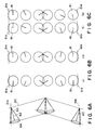
- an alignment state (C1 alignment state) comprising micro-regions 41 and 42 showing a small contrast is developed.
- C2 alignment state a high-contrast alignment state
- Figure 4B On further temperature decrease, the C2 alignment state is enlarged ( Figures 4C - 4D) to finally occupy the entire region ( Figure 4E).
- the two types of alignment states C1 and C2 may be explained by a difference in chevron structure of smectic layers as shown in Figure 5.
- 51 denotes a smectic layer
- 52 denotes a C1 alignment region
- 53 denotes a C2 alignment region
- 56 denotes a liquid crystal molecule.
- a smectic liquid crystal generally has a layer structure and, due to a shrinkage of spacing between layers when it causes a transition from SmA to SmC or SmC ⁇ , it assumes a chevron structure as shown in Figure 5 where the layers are bent at a mid point between a pair of substrates. The bending assumes two directions corresponding to C1 and C2 as shown in Figure 5.
- liquid crystal molecules contacting a substrate surface form an angle (pre-tilt angle) due to rubbing, the direction of which is such that the liquid crystal molecules raise a forward end up (i.e., spaced from the substrate surface) in the direction of rubbing as shown in Figure 5.
- the C1 and C2 alignment states are not equivalent regarding elastic energy, so that the above-mentioned transition is caused at a certain temperature.
- Such a transition can also caused by a mechanical distortion in some cases.
- a display of a higher quality is expected to be provided if the entire picture area of a display device is uniformly set in C1 alignment state, and the pair of bistable states giving a higher contrast is used for displaying two display states of white and black.
- the easiness of the C1 ⁇ C2 transition depends on the pre-tilt angle ⁇ formed between a substrate and liquid crystal molecules adjacent to the substrate surface, the inclination angle ⁇ of molecular layers and the tilt angle H of the liquid crystal as shown in Table 1 below.
- Table 1 shows that the C1 or C2 alignment state or a mixture thereof was formed in cases where three types of cells using three polyimide alignment films A - C having different pre-tilt angles were filled with three liquid crystals a - c showing different tilt angles.
- the polyimide alignment film A was prepared from "LP-64" (trade name, Toray K.K.)
- the polyimide alignment film B was prepared from "SE-610” (trade name, Nissan Kagaku K.K.)
- the polyimide alignment film C was prepared from a polyamide acid represented by the formula shown below, respectively by heat-curing.
- the alignment films A, B and C showed pre-tilt angles of 2.5 degrees, 6 degrees and 12 degrees, respectively.
- n is a polymerization degree of 2 - 50 calculated based on measured data obtained by GPC (gel permeation chromatography).
- Table 1 shows that a combination of a large pre-tilt angle and a small tilt angle allows the C1 alignment state to be be maintained.
- a liquid crystal is supplied with a voltage of one polarity for switching from a first optically stable state (e.g., a white display state) to a second optically stable state (e.g., a black display state) and then the voltage of one polarity is removed
- the ferroelectric liquid crystal layer is supplied with a reverse electric field Vrev due to the presence of the polyimide film as an insulating layer between the electrode and the liquid crystal layer, and the reverse electric field Vrev has caused an after-image during display.
- the generation of the above-mentioned reverse electric field has been reported in "Switching characteristic of SSFLC" by Akio Yoshida, "Preprint for Liquid Crystal Forum, October 1987" p.p. 142 - 143.
- Polyimide alignment layers used in supertwisted nematic liquid crystal devices are also know from EP-A-0 365 855.
- an object of the present invention is to provide a ferroelectric liquid crystal device having solved the above-mentioned problems, particularly a ferroelectric liquid crystal device which provides a large tilt angle of a chiral smectic liquid crystal in a non-helical structure and provides a display capable of displaying a high-contrast image and yet free from after-image.
- Another object of the present invention is to provide a display apparatus using such a liquid crystal device for display.
- a liquid crystal device comprising: a pair of substrates and a chiral smectic liquid crystal disposed between the substrates; at least one substrate of said pair of substrates having thereon an alignment film comprising a polyimide formed by dehydrocyclization of a polyamide acid which is a reaction product of a tetracarboxylic acid component selected from naphthalenetetracarboxylic acid and derivatives thereof with a diamine component selected from diamine and derivatives thereof, as defined in claim 1.
- a display apparatus comprising the above-mentioned liquid crystal device as a display panel; drive means for supplying signal voltages to the electrodes of the liquid crystal device; and control means for controlling the drive means.
- Figure 1 is a schematic sectional view of an embodiment of the liquid crystal device according to the present invention.
- Figure 2 is a perspective view showing schematically an alignment of a chiral smectic liquid crystal having a helical structure.
- Figure 3 is a perspective view showing schematically an alignment state of a chiral smectic liquid crystal having a non-helical structure.
- Figure 4A - 4E are sketches of polarizing microscopic views of a liquid crystal cell showing a series of changes in alignment state when an injected ferroelectric liquid crystal is gradually cooled from a higher temperature phase.
- Figure 5 is a schematic view for illustrating a difference between C1 and C2 alignment states.
- Figure 6A is a schematic sectional view showing an alignment state of a chiral smectic liquid crystal aligned according to the present invention
- Figure 6B is an illustration of C-director alignments in a uniform alignment state
- Figure 6C is an illustration of C-director alignments in a splay alignment state.
- Figures 7A and 7B are plan views illustrating tilt angles ⁇ in a uniform alignment state and a splay alignment state, respectively.
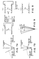
- Figure 8 is a sectional view showing a charge distribution, a direction of a spontaneous polarization P S and a direction of a reverse electric field Vrev.
- Figure 9 is a schematic plan view illustrating changes in tilt angle ⁇ during and after application of an electric field.
- Figures 10 and 11 are graphs showing optical response characteristics according to a conventional device and the present invention, respectively.
- Figure 12 is a block diagram of a liquid crystal display apparatus and a graphic controller.
- Figure 13 is a time chart showing time correlation for image data communication between the liquid crystal display apparatus and the graphic controller.
- Figure 14 is a waveform diagram illustrating driving waveforms used in an embodiment of the present invention.
- Figure 1 is a schematic sectional view of an embodiment of the liquid crystal device according to the present invention.
- the liquid crystal device comprises a pair of substrates (glass plates) 11a and 11b which are coated with transparent electrodes 12a and 12b of In 2 O 3 , ITO (indium tin oxide), etc., 200 - 1000 ⁇ -thick insulating films 13a and 13b of SiO 2 , TiO 2 , Ta 2 O 5 , etc., and 50 - 1000 ⁇ -thick alignment control films 14a and 14b.
- the alignment control films 14a and 14b have been treated by rubbing in directions which are parallel to each other and in the same direction (indicated by arrows A in Figure 1).
- a chiral smectic liquid crystal 15 is disposed between the substrates 11a and 11b, and the spacing between the substrates 11a and 11b is set to provide the liquid crystal layer 15 with a thickness (e.g., 0.1 - 3 microns) which is sufficiently small to suppress the formation of a helical structure of the chiral smectic liquid crystal 15 by disposing spacer beads 16 of, e.g., silica, alumina, etc. between the substrates 11a and 11b, whereby the chiral smectic liquid crystal 15 assumes a bistable alignment state.
- At least one of the alignment films 14a and 14b is constituted by a polyimide (in a sense of including oligomers such as dimers and trimers) formed by dehydrocyclization of a polyamide acid (also in a sense of including oligomers such as dimers and trimers) which has been obtained by reacting at least one acid component selected from naphthalene-tetracarboxylic acid and/or derivatives thereof with a diamine component selected from diamines and/or derivatives thereof.
- a polyimide in a sense of including oligomers such as dimers and trimers
- a polyamide acid also in a sense of including oligomers such as dimers and trimers
- naphthalenetetracarboxylic acid derivatives may include: 1,4,5,8-naphthalene-tetracarboxylic acid dianhydride, 1,2,3,4-naphthalenetetracarboxylic acid dianhydride, 1,2,5,6-naphthalenetetracarboxylic acid dianhydride and 2,3,6,7-naphthalenetetracarboxylic acid dianhydride.
- Such another acid component is not particularly limited but examples thereof may include: pyromellitic acid dianhydride, 3,3',4,4'-tetracarboxybiphenyl dianhydride, 2,3,3',4'-tetracarboxybiphenyl dianhydride, 3,3',4,4'-tetracarboxybiphenyl ether dianhydride, 3,3',4,4'-tetracarboxybenzophenone dianhydride, 2,3,3',4'-tetracarboxybenzophenone dianhydride, 3,3',4,4'-tetracarboxydiphenylmethane dianhydride, 2,2-bis(3,4-dicarboxyphenyl)propane dianhydride, 2,2-bis(3,4-dicarboxyphenyl)hexafluoropropan
- Such another acid component should be not more than 99 wt. %, preferably not more than 90 wt. % of the total acid components.
- the diamine component used in the present invention is selected from the group consisting of formulae (1) - (4).
- Z 1 - Z 6 independently denote a single bond, -O-, -CH 2 -, -S-, -SO 2 -, -CO-, -C(CH 3 ) 2 - or -C(CF 3 ) 2 -; and
- X 1 - X 10 independently denote H, F, CH 3 or CF 3 .
- the two amino groups are preferably at para- or meta-positions, and X 1 is preferably H.
- Z 1 is preferably a single bond, -S-, -CH 2 -, -C(CH 3 ) 2 - or -C(CF 3 ) 2 -;
- X 2 and X 3 are preferably H, CH 3 or CF 3 , more preferably H; and the two amino groups are preferably positioned at para-positions respectively with respect to the bonding group Z 1 .
- Z 2 and Z 3 are preferably a single bond, -O- or S;
- X 4 , X 5 and X 6 are preferably H, CH 3 or CF 3 ;
- Z 2 and Z 3 are preferably at para-positions with each other; and the two amino groups are preferably at para- or meta-positions with respect to the bonding groups Z 2 and Z 3 , respectively.
- Z 5 is preferably -C(CH 3 ) 2 - or -C(CF 3 ) 2 -;
- Z 4 and Z 6 are preferably -O-, -S- or -CH 2 -;
- X 8 and X 9 are preferably H;
- X 7 and X 10 are preferably H, F or CF 3 ;
- Z 4 and Z 6 are preferably at para-positions respectively with respect to Z 5 ; and the two amino groups are preferably at para- or meta-positions with respect to the bonding groups Z 4 and Z 6 , respectively.
- diamines represented by the formula (1) may include p-phenylenediamine and m-phenylenediamine.
- Examples of the diamines represented by the formula (2) may include: 4,4'-diaminodiphenyl ether, 4,4'-diaminodiphenylmethane, 4,4'-diaminophenyl sulfone, 2,2-bis(p-aminophenyl)propane, 2,2-bis(p-aminophenyl)hexafluoropropane, 3,3'-diaminodiphenyl ether, 3,3'-diaminodiphenylmethane, 3,3'-diaminodiphenyl sulfone, 3,3'-dimethyl-4,4'-diaminodiphenyl ether, 3,3'-dimethyl-4,4'-diaminodiphenylmethane, 3,3'-dimethyl-4,4'-diaminodiphenyl sulfone, 2,2-bis(m-aminophenyl)propane, 2,2-bis(
- Examples of the diamines represented by the formula (3) may include: 1,4''-diaminoterphenyl, 1,4-bis(p-aminophenoxy)benzene, 1,4-bis(m-aminophenoxy)benzene, 1,4-bis(4-amino-3-methylphenoxy)benzene and 1,4-bis(4-amino-3-trifluoromethylphenoxy)benzene.
- examples of the diamines represented by the formula (4) may include: 2,2-bis[(4-aminophenoxy)phenyl]propane, 2,2-bis[(4-amino-3-fluorophenoxy)phenyl]propane, trifluoromethylphenoxy)phenyl]propane, 2,2-bis[(4-amino-3-trifluoromethylphenoxy)phenyl]propane, 2,2-bis[(4-aminophenoxy)phenyl]hexafluoropropane, 2,2-bis[(4-amino-3-methylphenoxy)phenyl]hexafluoropropane, 2,2-bis[(4-amino-3-trifluoromethylphenoxy)phenyl]hexafluoropropane, 2,2-bis[(4-amino-2-fluorophenoxy)phenyl]propane, 2,2-bis[(4-amino-2-fluorophenoxy)phenyl]propane, 2,2-bis[(
- a solution of a polyamide acid as a precursor of the polyimide prepared as described above in a solvent such as dimethylformamide, dimethylacetoamide, dimethylsulfoxide or N-methylpyrrolidone at a concentration of 0.01 - 40 wt. % may be applied onto the substrate by spinner coating, spray coating, roller coating, etc., and heated at 100 - 350 °C, preferably 200 - 300 °C, to cause dehydro-cyclization.
- the thus-formed polyimide film may be rubbed with a cloth, etc.
- the polyimide film may be formed in a thickness of, e.g., 30 ⁇ - 1 micron, preferably 200 - 2000 ⁇ , so as to also function as an insulating film.
- the insulating films 13a and 13b can be omitted.
- the polyimide film thickness may be set to 200 ⁇ or less, preferably 100 ⁇ or less.
- the liquid crystal material 15 used in the present invention may preferably be one showing a phase transition from isotropic phase through cholesteric phase and smectic A phase into chiral smectic C phase in the course of temperature decrease.
- a chiral smectic liquid crystal showing a helical pitch of 0.8 micron or longer in cholesteric phase (measured at a mid temperature in the cholesteric range).
- Preferred examples of such a liquid crystal material may include liquid crystal materials (1) - (5) below comprising the following liquid crystals "LC-1", "80B” and "80SI ⁇ " in the indicated proportions by weight.
- FIG. 2 is a schematic illustration of a ferroelectric liquid crystal cell (device) for explaining operation thereof.
- Reference numerals 21a and 21b denote substrates (glass plates) on which a transparent electrode of, e.g., In 2 O 3 , SnO 2 , ITO (indium-tin-oxide), etc., is disposed, respectively.
- a liquid crystal of an SmC ⁇ -phase (chiral smectic C phase) or SmH ⁇ -phase (chiral smectic H phase) in which liquid crystal molecular layers 22 are aligned perpendicular to surfaces of the glass plates is hermetically disposed therebetween.
- Full lines 23 show liquid crystal molecules.
- Each liquid crystal molecule 23 has a dipole moment (P ⁇ ) 24 in a direction perpendicular to the axis thereof.
- the liquid crystal molecules 23 continuously form a helical structure in the direction of extension of the substrates.
- a voltage higher than a certain threshold level is applied between electrodes formed on the substrates 21a and 21b, a helical structure of the liquid crystal molecule 23 is unwound or released to change the alignment direction of respective liquid crystal molecules 23 so that the dipole moment (P ⁇ ) 24 are all directed in the direction of the electric field.
- the liquid crystal molecules 23 have an elongated shape and show refractive anisotropy between the long axis and the short axis thereof.
- the liquid crystal cell when, for instance, polarizers arranged in a cross nicol relationship, i.e., with their polarizing directions crossing each other, are disposed on the upper and the lower surfaces of the glass plates, the liquid crystal cell thus arranged functions as a liquid crystal optical modulation device of which optical characteristics vary depending upon the polarity of an applied voltage.
- the helical structure of the liquid crystal molecules is unwound to provide a non-helical structure even in the absence of an electric field, whereby the dipole moment assumes either of the two states, i.e., Pa in an upper direction 34a or Pb in a lower direction 34b as shown in Figure 3, thus providing a bistable condition.
- an electric field Ea or Eb higher than a certain threshold level and different from each other in polarity as shown in Figure 3 is applied to a cell having the above-mentioned characteristics, the dipole moment is directed either in the upper direction 34a or in the lower direction 34b depending on the vector of the electric field Ea or Eb.
- the liquid crystal molecules are oriented in either of a first stable state 33a and a second stable state 33b.
- a first advantage attained by using such a ferroelectric liquid crystal cell is that the response speed is quite fast, and a second advantage is that the orientation of the liquid crystal shows bistability.
- the second advantage will be further explained, e.g., with reference to Figure 3.
- the electric field Ea When the electric field Ea is applied to the liquid crystal molecules, they are oriented in the first stable state 33a. This state is stably retained even if the electric field is removed.
- the electric field Eb of which direction is opposite to that of the electric field Ea is applied thereto, the liquid crystal molecules are oriented to the second stable state 33b, whereby the directions of molecules are changed. This state is similarly stably retained even if the electric field is removed. Further, as long as the magnitude of the electric field Ea or Eb being applied is not above a certain threshold value, the liquid crystal molecules are placed in the respective orientation states.
- Figure 6A is a schematic sectional view showing an alignment state of liquid crystal molecules attained by the present invention
- Figure 6B is a view showing alignment of corresponding C-directors.
- Reference numerals 61a and 61b in Figure 6A denote upper and lower substrates, respectively.
- Numeral 60 denotes a molecular layer composed of liquid crystal molecules 62, and liquid crystal molecules 62 are aligned so as to change their positions along the bottom face 64 (circular) of a cone 64.
- Figure 6B more specifically shows a change in C-directors. Referring to Figure 6B, at U 1 are shown C-directors 81 (each being a projection of a molecular long axis onto an imaginary plane perpendicular to the normal to a molecular layer 60) in one stable orientation state, and at U 2 are shown C-directors 81 in the other stable orientation state.
- an alignment state attained by a conventional rubbing-treated polyimide film may be represented by a C-director diagram of Figure 6C, which shows an alignment state wherein molecular axes are twisted in a large degree from the upper substrate 61a to the lower substrate 61b to provide a smaller tilt angle ⁇ .
- Figure 7A is a schematic plan view illustrating a tilt angle ⁇ in an alignment state where C-directors 81 assume a state shown in Figure 6B (referred to as "uniform alignment state")
- Figure 7B is a schematic plan view illustrating a tilt angle ⁇ in an alignment state where C-directors 81 assume a state shown in Figure 6C (referred to as "splay alignment state").
- reference numeral 70 denotes a rubbing axis provided to the above-mentioned fluorine-containing polyimide film
- numeral 71a denotes an average molecular axis in the orientation state U 1
- numeral 71b denotes an average molecular axis in the orientation state U 2
- numeral 72a denotes an average molecular axis in the orientation state S 1
- numeral 72b denotes an average molecular axis in the orientation state S 2 .
- the average molecular axes 71a and 71b can be switched to each other by applying voltages of mutually opposite polarities. Similar switching is caused between the average molecular axes 72a and 72b.
- Vrev 2P S /(Ci+C LC )
- Figure 8 is a schematic sectional view illustrating changes in charge distribution direction of P S and direction of the reverse electric field in a liquid crystal cell.
- Figure 8(a) there is shown a distribution of ⁇ and ⁇ charges in a memory state before application of a pulse electric field, where the spontaneous polarization is directed from ⁇ charges to ⁇ charges.
- FIG 8(b) is shown a state immediately after removal of a pulse electric field, when the direction of the spontaneous polarization P S is opposite to that shown at Figure 8(a) (thus, the liquid crystal molecules are inverted from one stable orientation state to the other orientation state) but the distribution of the ⁇ and ⁇ charges is similar to that shown at Figure 8(a), so that a reverse electric field Vrev is generated as indicated by an arrow shown at Figure 8(b).
- the reverse electric field Vrev disappears in a short time to provide a distribution of ⁇ and ⁇ charges as shown at Figure 8(c).
- Figure 9 is a plan view showing a change in optical response in a splay alignment state given by a conventional polyimide alignment film in terms of a change in tilt angle ⁇ .
- the orientation of liquid crystal molecules is changed from an average molecular axis S(A) in a splay alignment state to be overshot to an average molecular axis U 2 in a uniform alignment state close to that providing a maximum tilt angle H along a path denoted by an arrow X 1 , and immediately after the removal of the pulse electric field, the orientation is changed along a path denoted by an arrow X 2 to an average molecular axis S(B) in a splay alignment state providing a decreased tilt angle ⁇ due to the action of the reverse electric field Vrev shown at Figure 8(b).
- the average molecular axes S(A), S(B) and S(C) in the splay alignment state shown in Figure 9 are not caused but it is possible to form an alignment state with an average molecular axis giving a tilt angle ⁇ which is close to a maximum tilt angle H .
- An optical response at this time according to the present invention is shown in Figure 11.
- Figure 11 shows that a delay in optical response causing after-image is obviated and a high contrast in memory states is caused.
- a liquid crystal display apparatus may be constituted by using the liquid crystal device for a display panel and by adopting an arrangement and data format comprising image data accompanied with scanning line address data and also a communication synchronization scheme using a SYNC signal as shown in Figures 12 and 13.
- Image data are generated in a graphic controller 102 in an apparatus body and transferred to the display panel 103 (illuminated with a backlight (not shown)) by signal transfer means shown in Figures 12 and 13.
- the graphic controller 102 principally comprises a CPU (or GCPU, central processing unit) 112 and a VRAM (video-RAM, image data storage memory) 114 and is in charge of management and communication of image data between a host CPU 113 and the liquid crystal display apparatus (FLCD) 101.
- the control of image display according to the present invention is principally accomplished by the graphic controller 102.
- Reference numerals 103 to 105 and 107 to 111 concern specific elements of the FLC display and need not be further described here.
- liquid crystal device in the liquid crystal device according to the present invention, it is also possible to use a nematic liquid crystal in place of the above-mentioned chiral smectic liquid crystal.
- the film was subjected to curing under heating at 250 o C for about an hour to form a 450 ⁇ -thick film.
- the coating film was then rubbed in one direction with a nylon-planted cloth.
- the blank cell was filled with a ferroelectric smectic liquid crystal ("CS-1014" (trade name), available from Chisso K.K.) under vacuum and, after sealing, was gradually cooled from isotropic phase at a rate of 5 °C/hour to 30 °C, whereby an alignment was effected.
- CS-1014 ferroelectric smectic liquid crystal
- the above-prepared liquid crystal cell was sandwiched between a pair of 90 degrees-cross nicol polarizers to provide a liquid crystal device and was supplied with a pulse of 50 ⁇ sec and 30 V. Then, the cross nicol polarizers were set at the extinction position (providing the darkest state), and the transmittance through the liquid crystal device at this time was measured by a photo-multiplier. Then, a pulse of 50 ⁇ sec and -30 V was applied to the device, and the transmittance (brightest state) at this time was measured in the same manner, whereby the following data were obtained.
- the delay in optical response causing after-image was 0.2 sec or less.
- the liquid crystal device was subjected to multiplexing drive for display using driving waveforms shown in Figure 14, whereby a high-quality display with a high contrast was attained. Further, after an image display of a prescribed character image, the whole picture area was erased into "white", whereby no after-image was recognized.
- S N S N+1 and S N+2 are shown voltage waveforms applied to scanning lines
- I is shown a voltage waveform applied to a representative date line
- at (I-S N ) is shown a combined voltage waveform applied to the data line I and the scanning line S N .
- Liquid crystal cells were prepared in the same manner as in Example 1 except that the alignment control films (in terms of precursor polyamide acids represented by the formulas wherein n and m respectively denotes a polymerization degree calculated based on measured data by GPC) and liquid crystal materials shown in Table 1 below were used.
- the alignment control films in terms of precursor polyamide acids represented by the formulas wherein n and m respectively denotes a polymerization degree calculated based on measured data by GPC
- Table 1 liquid crystal materials
- the respective cells were subjected to the multiplexing drive for display in the same manner as in Example 1, whereby similar results were attained with respect to contrast and after-image.
- Example Contrast ratio Delay in optical response (sec) 2 37:1 0.2 3 32:1 0.3 4 46:1 0.2 5 41:1 0.3 6 31:1 0.3 7 33:1 0.1 8 39:1 0.1 9 35:1 0.2 10 32:1 0.1 11 45:1 0.1 12 38:1 0.1 13 40:1 0.2 14 37:1 0.1 15 36:1 0.2 16 30:1 0.3 17 33:1 0.2
- Liquid crystal cells were prepared in the same manner as in Example 1 except that the alignment control films (in terms of commercially available precursor polyamide acid varnish and liquid crystal materials shown in Table 4 below were used.
- the measured data of contrast ratio and delay in optical response measured for each of the cells are shown in Table 5 below.
- the liquid crystal device in the liquid crystal device according to the present invention, a monodomain of a uniform and good alignment state is developed.
- the liquid crystal device provides a high-quality display which is characterized by a high contrast between the bright and dark states, particularly a very large contrast at the time of multiplexing drive and it free from unpleasant after-image.
- a liquid crystal device is formed by applying an alignment film on at least one of a pair of substrates sandwiching a chiral smectic liquid crystal.
- the alignment is formed by a dehydro-cyclization product of a polyamide acid which in turn is a reaction product of naphthalenetetracarboxylic acid or its derivative with a diamine or its derivative.
- the liquid crystal device provides a high contrast display, particularly by multiplexing drive, which is free from after-image because of quick responsiveness.
Landscapes
- Chemical & Material Sciences (AREA)
- Physics & Mathematics (AREA)
- Chemical Kinetics & Catalysis (AREA)
- Nonlinear Science (AREA)
- Health & Medical Sciences (AREA)
- Medicinal Chemistry (AREA)
- Polymers & Plastics (AREA)
- Organic Chemistry (AREA)
- Mathematical Physics (AREA)
- Crystallography & Structural Chemistry (AREA)
- General Physics & Mathematics (AREA)
- Optics & Photonics (AREA)
- Spectroscopy & Molecular Physics (AREA)
- Liquid Crystal (AREA)
- Indicating Measured Values (AREA)
Claims (8)
- Flüssigkristallvorrichtung, die die nachstehenden Bestandteile umfaßt:
ein Substratpaar und einen zwischen den Substraten angeordneten chiralen smektischen Flüssigkristall, wobei sich auf mindestens einem Substrat des Substratpaars ein Ausrichtungsfilm befindet, der ein Polyimid umfaßt, das nur Seitenketten und Substituenten aufweist, die aus der Gruppe bestehend aus H, F, CH3 und CF3 ausgewählt sind, und das durch die Dehydrocyclisierung einer Polyamidsäure hergestellt wurde, die das Reaktionsprodukt aus:(i) einem Tetracarbonsäurebestandteil, ausgewählt aus Naphthalintetracarbonsäure und Derivaten davon, mit(ii) einem Diaminbestandteil, ausgewählt aus der Gruppe bestehend aus den Formeln (1)-(4), ist:wobei Z1 eine Einfachbindung, -CH2-, -S-, -CO-, -C(CH3)2-oder -C(CF3)2- darstellt; Z2-Z6 stellen unabhängig eine Einfachbindung, -O-, -CH2-, -S-, -CO-, -C(CH3)2- oder -C(CF3)2- dar; und X1 bis X10 stellen unabhängig H, F, CH3 oder CF3 dar, um eine Ausrichtungstruktur mit einem Bereich eines Cl-Ausrichtungszustands zu bilden, in dem eine Vielzahl smektischer Schichten, die jeweils mehrere Flüssigkristallmoleküle umfassen, zueinander parallel ausgerichtet sind, wobei die vielen Flüssigkristallmoleküle so ausgerichtet werden, daß sie sich dergestalt ausdehnen, daß ihre vorderen Enden in bezug auf das Substratpaar spitze Vor-Neigungswinkel definieren und sich die Ausdehnungsrichtungen der vielen Flüssigkristallmoleküle, die an dem Substratpaar angrenzen, einander schneiden, und wobei die Vielzahl smektischer Schichten in einer Richtung gebogen ist, die der Vorwärtsrichtung der Moleküle entgegengesetzt ist.


- Vorrichtung nach Anspruch 1, wobei der Tetracarbonsäurebestandteil 1,4,5,8-Naphthalintetracarbonsäuredianhydrid umfaßt.
- Vorrichtung nach Anspruch 1, wobei der Tetracarbonsäurebestandteil 2,3,6,7-Naphthalintetracarbonsäuredianhydrid umfaßt.
- Vorrichtung nach Anspruch 1, wobei der Diaminbestandteil durch die Formel (1) repräsentiert wird, wobei die zwei Aminogruppen sich unabhängig in para- oder meta-Positionen befinden und X1 H ist.
- Vorrichtung nach Anspruch 1, wobei der Diaminbestandteil durch die Formel (2) repräsentiert wird, wobei Z1 eine Einfachbindung, -S-, -CH2-, -C(CH3)2- oder -C(CF3)2-darstellt; X2 und X3 stellen H, CH3 oder CF3 dar, und die zwei Aminogruppen befinden sich beide in bezug auf die Bindungsgruppe Z1 in para-Positionen.
- Vorrichtung nach Anspruch 1, wobei der Diaminbestandteil durch die Formel (3) repräsentiert wird, wobei Z2 und Z3 eine Einfachbindung, -O- oder -S- darstellen; X4, X5 und X6 stellen H, CH3 oder CF3 dar; Z2 und Z3 befinden sich in bezug zueinander in para-Positionen; und die zwei Aminogruppen befinden sich in bezug auf die Bindungsgruppen Z2 beziehungsweise Z3 unabhängig in para- oder meta-Positionen.
- Vorrichtung nach Anspruch 1, wobei der Diaminbestandteil durch die Formel (4) repräsentiert wird, wobei Z5 C(CH3)2 oder C(CF3)2 darstellt; Z4 und Z6 stellen -O-, -S- oder CH2 dar; X8 und X9 stellen H dar; X7 und X10 stellen H, F oder CF3 dar; Z4 und Z6 befinden sich in bezug auf Z5 beide in para-Positionen; und die zwei Aminogruppen befinden sich in bezug auf die Bindungsgruppen Z4 beziehungsweise Z6 unabhängig in para- oder meta-Positionen.
- Anzeigevorrichtung, die die nachstehenden Bestandteile umfaßt:(a) eine Flüssigkristallvorrichtung nach einem der Ansprüche 1 bis 7, in der jedes der Substrate eine darauf aufgebrachte Elektrode aufweist;(b) eine Ansteuerungseinrichtung für die Versorgung der Elektroden mit Signalspannungen; und(c) eine Steuereinrichtung zum Steuern der Ansteuerungseinrichtung.
Applications Claiming Priority (2)
| Application Number | Priority Date | Filing Date | Title |
|---|---|---|---|
| JP17633/91 | 1991-02-08 | ||
| JP3017633A JPH04255827A (ja) | 1991-02-08 | 1991-02-08 | 液晶素子 |
Publications (3)
| Publication Number | Publication Date |
|---|---|
| EP0499159A2 EP0499159A2 (de) | 1992-08-19 |
| EP0499159A3 EP0499159A3 (en) | 1993-04-28 |
| EP0499159B1 true EP0499159B1 (de) | 1997-05-07 |
Family
ID=11949271
Family Applications (1)
| Application Number | Title | Priority Date | Filing Date |
|---|---|---|---|
| EP92102070A Expired - Lifetime EP0499159B1 (de) | 1991-02-08 | 1992-02-07 | Flüssigkristallvorrichtung und Anzeigevorrichtung |
Country Status (5)
| Country | Link |
|---|---|
| US (1) | US5419932A (de) |
| EP (1) | EP0499159B1 (de) |
| JP (1) | JPH04255827A (de) |
| AT (1) | ATE152841T1 (de) |
| DE (1) | DE69219493T2 (de) |
Families Citing this family (11)
| Publication number | Priority date | Publication date | Assignee | Title |
|---|---|---|---|---|
| GB2264713B (en) * | 1992-02-05 | 1996-09-25 | Canon Kk | Liquid crystal device |
| US5419931A (en) * | 1992-09-18 | 1995-05-30 | Canon Kabushiki Kaisha | Liquid crystal device |
| US5460749A (en) * | 1992-12-25 | 1995-10-24 | Canon Kabushiki Kaisha | Liquid crystal device and liquid crystal display apparatus |
| JP3365563B2 (ja) * | 1993-01-22 | 2003-01-14 | 日産化学工業株式会社 | 液晶セル用配向処理剤 |
| US5587211A (en) * | 1994-04-18 | 1996-12-24 | Canon Kabushiki Kaisha | Liquid crystal device and liquid crystal apparatus including same |
| US5885482A (en) * | 1995-12-28 | 1999-03-23 | Canon Kabushiki Kaisha | Liquid crystal device, production process thereof and liquid crystal apparatus |
| JP3192593B2 (ja) * | 1996-07-22 | 2001-07-30 | キヤノン株式会社 | 液晶素子 |
| JPH10332925A (ja) * | 1997-06-02 | 1998-12-18 | Canon Inc | カラーフィルタ基板とその製造方法、該基板を用いた液晶素子 |
| JPH11100577A (ja) * | 1997-07-31 | 1999-04-13 | Canon Inc | 液晶の配向方法、液晶素子の製造方法、該製造方法により得られる液晶素子、液晶装置 |
| US6195147B1 (en) | 1997-08-01 | 2001-02-27 | Canon Kabushiki Kaisha | Liquid crystal substrate with optical modulation region having different alignment control forces |
| US6139927A (en) * | 1997-09-18 | 2000-10-31 | Canon Kabushiki Kaisha | Liquid crystal device |
Family Cites Families (8)
| Publication number | Priority date | Publication date | Assignee | Title |
|---|---|---|---|---|
| US4367924A (en) * | 1980-01-08 | 1983-01-11 | Clark Noel A | Chiral smectic C or H liquid crystal electro-optical device |
| US4561726A (en) * | 1983-07-29 | 1985-12-31 | At&T Bell Laboratories | Alignment of ferroelectric LCDs |
| DE3669079D1 (de) * | 1985-07-10 | 1990-03-29 | Hitachi Ltd | Ferroelektrisches fluessigkristallelement und verfahren zu dessen herstellung. |
| EP0219336B1 (de) * | 1985-10-14 | 1993-07-21 | Hitachi Chemical Co., Ltd. | Schicht zur Steuerung der Flüssigkristallorientierung und ihre Anwendung in einer Flüssigkristallvorrichtung |
| US4802743A (en) * | 1986-03-20 | 1989-02-07 | Canon Kabushiki Kaisha | Liquid crystal device having color filters wherein the color filters formed from a polyamino resin containing coloring materials |
| US4820026A (en) * | 1986-03-20 | 1989-04-11 | Canon Kabushiki Kaisha | Ferroelectric liquid crystal device with modified polyvinyl alcohol alignment film |
| JPH02176631A (ja) * | 1988-09-28 | 1990-07-09 | Hitachi Chem Co Ltd | 液晶配向膜用組成物,液晶配向膜および液晶表示素子 |
| CA2024445C (en) * | 1989-09-01 | 1994-11-08 | Yuko Morikawa | Liquid crystal device |
-
1991
- 1991-02-08 JP JP3017633A patent/JPH04255827A/ja active Pending
-
1992
- 1992-02-07 AT AT92102070T patent/ATE152841T1/de not_active IP Right Cessation
- 1992-02-07 DE DE69219493T patent/DE69219493T2/de not_active Expired - Fee Related
- 1992-02-07 EP EP92102070A patent/EP0499159B1/de not_active Expired - Lifetime
-
1994
- 1994-01-24 US US08/185,164 patent/US5419932A/en not_active Expired - Fee Related
Also Published As
| Publication number | Publication date |
|---|---|
| EP0499159A3 (en) | 1993-04-28 |
| US5419932A (en) | 1995-05-30 |
| DE69219493T2 (de) | 1997-11-27 |
| ATE152841T1 (de) | 1997-05-15 |
| DE69219493D1 (de) | 1997-06-12 |
| EP0499159A2 (de) | 1992-08-19 |
| JPH04255827A (ja) | 1992-09-10 |
Similar Documents
| Publication | Publication Date | Title |
|---|---|---|
| EP0400635B1 (de) | Flüssigkristall-Vorrichtung | |
| EP0550846B1 (de) | Ferroelektrische Flüssigkristall-Anzeigevorrichtung und Verfahren zu ihrer Herstellung | |
| EP0450549B1 (de) | Flüssigkristallvorrichtung | |
| EP0539992B1 (de) | Flüssigkristall-Anzeigevorrichtung | |
| EP0160302A2 (de) | Ferroelektrische Flüssigkristall-Zelle | |
| EP0629893A1 (de) | Flüssigkristallvorrichtung | |
| US5426525A (en) | Ferroelectric smectic liquid crystal device | |
| US5268780A (en) | Liquid crystal device having a polyimide alignment film substituted with fluorine or a fluorine-containing group | |
| US5326600A (en) | Liquid crystal device | |
| EP0499159B1 (de) | Flüssigkristallvorrichtung und Anzeigevorrichtung | |
| EP0538841B1 (de) | Flüssigkristallvorrichtung | |
| US5330803A (en) | Liquid crystal device | |
| US5571580A (en) | Liquid crystal device | |
| US5400159A (en) | Liquid crystal device having alignment film with particular surface energy difference before and after rubbing | |
| US5576864A (en) | Chiral smectic liquid crystal device having fluorine-containing polymeric alignment film with predetermined refractive index anisotropy after rubbing | |
| US5464668A (en) | Liquid crystal device | |
| US5250330A (en) | Liquid crystal device | |
| US5587211A (en) | Liquid crystal device and liquid crystal apparatus including same | |
| EP0397153B1 (de) | Chiralsmektische Flüssigkristallvorrichtung | |
| US5518782A (en) | Liquid crystal device | |
| US5422749A (en) | Ferroelectric smetic liquid crystal device | |
| US5714209A (en) | Liquid crystal device | |
| US5626925A (en) | Liquid crystal device | |
| JP2675893B2 (ja) | 液晶素子 | |
| JPH0618900A (ja) | 液晶表示素子 |
Legal Events
| Date | Code | Title | Description |
|---|---|---|---|
| PUAI | Public reference made under article 153(3) epc to a published international application that has entered the european phase |
Free format text: ORIGINAL CODE: 0009012 |
|
| 17P | Request for examination filed |
Effective date: 19920207 |
|
| AK | Designated contracting states |
Kind code of ref document: A2 Designated state(s): AT BE CH DE DK ES FR GB GR IT LI LU NL PT SE |
|
| PUAL | Search report despatched |
Free format text: ORIGINAL CODE: 0009013 |
|
| AK | Designated contracting states |
Kind code of ref document: A3 Designated state(s): AT BE CH DE DK ES FR GB GR IT LI LU NL PT SE |
|
| 17Q | First examination report despatched |
Effective date: 19950331 |
|
| GRAG | Despatch of communication of intention to grant |
Free format text: ORIGINAL CODE: EPIDOS AGRA |
|
| GRAH | Despatch of communication of intention to grant a patent |
Free format text: ORIGINAL CODE: EPIDOS IGRA |
|
| GRAH | Despatch of communication of intention to grant a patent |
Free format text: ORIGINAL CODE: EPIDOS IGRA |
|
| GRAA | (expected) grant |
Free format text: ORIGINAL CODE: 0009210 |
|
| AK | Designated contracting states |
Kind code of ref document: B1 Designated state(s): AT BE CH DE DK ES FR GB GR IT LI LU NL PT SE |
|
| PG25 | Lapsed in a contracting state [announced via postgrant information from national office to epo] |
Ref country code: GR Free format text: LAPSE BECAUSE OF FAILURE TO SUBMIT A TRANSLATION OF THE DESCRIPTION OR TO PAY THE FEE WITHIN THE PRESCRIBED TIME-LIMIT Effective date: 19970507 Ref country code: LI Effective date: 19970507 Ref country code: ES Free format text: THE PATENT HAS BEEN ANNULLED BY A DECISION OF A NATIONAL AUTHORITY Effective date: 19970507 Ref country code: CH Effective date: 19970507 Ref country code: AT Effective date: 19970507 Ref country code: BE Effective date: 19970507 Ref country code: DK Effective date: 19970507 |
|
| REF | Corresponds to: |
Ref document number: 152841 Country of ref document: AT Date of ref document: 19970515 Kind code of ref document: T |
|
| REG | Reference to a national code |
Ref country code: CH Ref legal event code: EP |
|
| ITF | It: translation for a ep patent filed | ||
| REF | Corresponds to: |
Ref document number: 69219493 Country of ref document: DE Date of ref document: 19970612 |
|
| ET | Fr: translation filed | ||
| PG25 | Lapsed in a contracting state [announced via postgrant information from national office to epo] |
Ref country code: PT Effective date: 19970807 Ref country code: SE Effective date: 19970807 |
|
| REG | Reference to a national code |
Ref country code: CH Ref legal event code: PL |
|
| PG25 | Lapsed in a contracting state [announced via postgrant information from national office to epo] |
Ref country code: LU Free format text: LAPSE BECAUSE OF NON-PAYMENT OF DUE FEES Effective date: 19980207 |
|
| PLBE | No opposition filed within time limit |
Free format text: ORIGINAL CODE: 0009261 |
|
| STAA | Information on the status of an ep patent application or granted ep patent |
Free format text: STATUS: NO OPPOSITION FILED WITHIN TIME LIMIT |
|
| 26N | No opposition filed | ||
| REG | Reference to a national code |
Ref country code: GB Ref legal event code: IF02 |
|
| PGFP | Annual fee paid to national office [announced via postgrant information from national office to epo] |
Ref country code: GB Payment date: 20060201 Year of fee payment: 15 |
|
| PGFP | Annual fee paid to national office [announced via postgrant information from national office to epo] |
Ref country code: DE Payment date: 20060202 Year of fee payment: 15 |
|
| PGFP | Annual fee paid to national office [announced via postgrant information from national office to epo] |
Ref country code: NL Payment date: 20060215 Year of fee payment: 15 |
|
| PGFP | Annual fee paid to national office [announced via postgrant information from national office to epo] |
Ref country code: FR Payment date: 20060220 Year of fee payment: 15 |
|
| PGFP | Annual fee paid to national office [announced via postgrant information from national office to epo] |
Ref country code: IT Payment date: 20060228 Year of fee payment: 15 |
|
| GBPC | Gb: european patent ceased through non-payment of renewal fee |
Effective date: 20070207 |
|
| NLV4 | Nl: lapsed or anulled due to non-payment of the annual fee |
Effective date: 20070901 |
|
| REG | Reference to a national code |
Ref country code: FR Ref legal event code: ST Effective date: 20071030 |
|
| PG25 | Lapsed in a contracting state [announced via postgrant information from national office to epo] |
Ref country code: DE Free format text: LAPSE BECAUSE OF NON-PAYMENT OF DUE FEES Effective date: 20070901 Ref country code: NL Free format text: LAPSE BECAUSE OF NON-PAYMENT OF DUE FEES Effective date: 20070901 |
|
| PG25 | Lapsed in a contracting state [announced via postgrant information from national office to epo] |
Ref country code: GB Free format text: LAPSE BECAUSE OF NON-PAYMENT OF DUE FEES Effective date: 20070207 Ref country code: FR Free format text: LAPSE BECAUSE OF NON-PAYMENT OF DUE FEES Effective date: 20070228 |
|
| PG25 | Lapsed in a contracting state [announced via postgrant information from national office to epo] |
Ref country code: IT Free format text: LAPSE BECAUSE OF NON-PAYMENT OF DUE FEES Effective date: 20070207 |