EP0499218A1 - Frein de fil - Google Patents
Frein de fil Download PDFInfo
- Publication number
- EP0499218A1 EP0499218A1 EP92102286A EP92102286A EP0499218A1 EP 0499218 A1 EP0499218 A1 EP 0499218A1 EP 92102286 A EP92102286 A EP 92102286A EP 92102286 A EP92102286 A EP 92102286A EP 0499218 A1 EP0499218 A1 EP 0499218A1
- Authority
- EP
- European Patent Office
- Prior art keywords
- thread
- brake
- brake according
- guide element
- thread brake
- Prior art date
- Legal status (The legal status is an assumption and is not a legal conclusion. Google has not performed a legal analysis and makes no representation as to the accuracy of the status listed.)
- Granted
Links
- 230000003534 oscillatory effect Effects 0.000 claims description 11
- 238000003780 insertion Methods 0.000 claims description 5
- 230000037431 insertion Effects 0.000 claims description 5
- 230000010355 oscillation Effects 0.000 claims description 4
- 230000009471 action Effects 0.000 claims description 3
- 230000007246 mechanism Effects 0.000 claims description 3
- 230000006835 compression Effects 0.000 description 7
- 238000007906 compression Methods 0.000 description 7
- 230000000694 effects Effects 0.000 description 5
- 238000009940 knitting Methods 0.000 description 4
- 239000000463 material Substances 0.000 description 4
- 239000000919 ceramic Substances 0.000 description 2
- 229910010293 ceramic material Inorganic materials 0.000 description 2
- 238000004140 cleaning Methods 0.000 description 2
- 239000013013 elastic material Substances 0.000 description 2
- 230000005284 excitation Effects 0.000 description 2
- 239000000314 lubricant Substances 0.000 description 2
- 239000000696 magnetic material Substances 0.000 description 2
- 238000000034 method Methods 0.000 description 2
- 230000008569 process Effects 0.000 description 2
- 238000004804 winding Methods 0.000 description 2
- 229910000831 Steel Inorganic materials 0.000 description 1
- 238000009825 accumulation Methods 0.000 description 1
- 238000013459 approach Methods 0.000 description 1
- 238000005452 bending Methods 0.000 description 1
- 230000008901 benefit Effects 0.000 description 1
- 230000000903 blocking effect Effects 0.000 description 1
- 230000008878 coupling Effects 0.000 description 1
- 238000010168 coupling process Methods 0.000 description 1
- 238000005859 coupling reaction Methods 0.000 description 1
- 230000001419 dependent effect Effects 0.000 description 1
- 230000008021 deposition Effects 0.000 description 1
- 238000011161 development Methods 0.000 description 1
- 230000018109 developmental process Effects 0.000 description 1
- 239000000835 fiber Substances 0.000 description 1
- 230000005484 gravity Effects 0.000 description 1
- 230000001771 impaired effect Effects 0.000 description 1
- 230000001788 irregular Effects 0.000 description 1
- 230000009191 jumping Effects 0.000 description 1
- 239000002245 particle Substances 0.000 description 1
- 235000011837 pasties Nutrition 0.000 description 1
- 238000003825 pressing Methods 0.000 description 1
- 238000012545 processing Methods 0.000 description 1
- 239000010959 steel Substances 0.000 description 1
- 239000004753 textile Substances 0.000 description 1
Images







Classifications
-
- D—TEXTILES; PAPER
- D04—BRAIDING; LACE-MAKING; KNITTING; TRIMMINGS; NON-WOVEN FABRICS
- D04B—KNITTING
- D04B15/00—Details of, or auxiliary devices incorporated in, weft knitting machines, restricted to machines of this kind
- D04B15/38—Devices for supplying, feeding, or guiding threads to needles
- D04B15/44—Tensioning devices for individual threads
-
- B—PERFORMING OPERATIONS; TRANSPORTING
- B65—CONVEYING; PACKING; STORING; HANDLING THIN OR FILAMENTARY MATERIAL
- B65H—HANDLING THIN OR FILAMENTARY MATERIAL, e.g. SHEETS, WEBS, CABLES
- B65H59/00—Adjusting or controlling tension in filamentary material, e.g. for preventing snarling; Applications of tension indicators
- B65H59/10—Adjusting or controlling tension in filamentary material, e.g. for preventing snarling; Applications of tension indicators by devices acting on running material and not associated with supply or take-up devices
- B65H59/20—Co-operating surfaces mounted for relative movement
- B65H59/22—Co-operating surfaces mounted for relative movement and arranged to apply pressure to material
- B65H59/225—Tension discs
-
- B—PERFORMING OPERATIONS; TRANSPORTING
- B65—CONVEYING; PACKING; STORING; HANDLING THIN OR FILAMENTARY MATERIAL
- B65H—HANDLING THIN OR FILAMENTARY MATERIAL, e.g. SHEETS, WEBS, CABLES
- B65H2555/00—Actuating means
- B65H2555/10—Actuating means linear
- B65H2555/13—Actuating means linear magnetic, e.g. induction motors
-
- B—PERFORMING OPERATIONS; TRANSPORTING
- B65—CONVEYING; PACKING; STORING; HANDLING THIN OR FILAMENTARY MATERIAL
- B65H—HANDLING THIN OR FILAMENTARY MATERIAL, e.g. SHEETS, WEBS, CABLES
- B65H2701/00—Handled material; Storage means
- B65H2701/30—Handled filamentary material
- B65H2701/31—Textiles threads or artificial strands of filaments
Definitions
- the invention relates to a thread brake with two, preferably disc or plate-shaped brake elements resiliently pressed against one another by load means, between which at least one thread to be braked can be carried out and which are mounted on a common bearing axis bearing means and are under the action of a device which sets them into oscillatory movements .
- the object of the invention is to remedy this and to create a thread brake of the type mentioned, which is characterized by an improved self-cleaning effect, i.e. the occurrence of undesirable deposits of lubricants etc. is effectively prevented and, at the same time, uniform thread braking is ensured over long operating periods.
- the brake elements are mounted on a guide element containing the bearing axis, the brake elements being able to be set in oscillatory movements together with the guide element.
- the guide element can be rigid, for example a cylindrical bolt.
- the guide element is at least partially elastic, which e.g. can be achieved in that the guide element is made of a corresponding plastic material.
- the guide element is elastically mounted in mounting means so that it receives the required mobility at its bearing point.
- the braking elements themselves are advantageously mounted on the guide element with radial play, so that they can carry out a certain movement in the direction of vibration which is independent of the guide element.
- practical experience has shown that with the usual thread brakes of the type in question here it is expedient that the oscillating movements have a frequency of approximately 40 to 500 Hz.
- the thread brake can be arranged on a thread delivery device having a revolving shaft, the link carrying out the reciprocating movement being coupled to the shaft via a gear generating this movement.
- the shaft rotating in these thread delivery devices generally drives a thread delivery element, for example in the form of a thread storage roll, or a thread winding element. It is in turn driven by a drive source, which in practice in the case of a circular knitting machine often consists of an endless toothed belt with which the shafts of the individual thread delivery devices are each coupled via a toothed belt pulley and which in turn is rotated synchronously with the needle cylinder.
- embodiments of the thread brake are also advantageous, in which the vibration generating device is designed to act directly on the brake elements, for example by acting on the circumference thereof.
- the gear mechanism mentioned can be a cam mechanism with a cam element seated on the shaft, against the cam surface of which the reciprocating member is held in contact.
- “Cam gears” are understood to mean all form-fitting gears that generate a vibratory movement, for example also eccentric gears etc.
- the basic structure of the thread delivery device shown in FIGS. 1, 2 is known. It has a holder 1 which, for example, by means of a clamping screw 2 on a support ring indicated at 3. a circular knitting machine, can be fastened and in which a continuous shaft 4 is rotatably mounted, which has a vertical orientation when the holder 1 is mounted in the operating position.
- the shaft 4 is connected at one end to a thread drum 5 arranged below the holder 1 and designed in the form of a rod cage; it carries at its upper end a toothed belt pulley 7 which can be coupled in a rotationally fixed manner via a coupling 6 and via which the thread drum 5 can be rotated from an endless toothed belt (not shown further).
- a plate thread brake 8 is arranged, which has two identical, essentially disk-shaped brake plates 9, between which the thread indicated at 10 passes.
- the thread path extends from a thread spool, not shown, through a thread eyelet 11 fastened to the holder 1, a knot catcher 12, the thread brake 8 to a thread inlet eyelet 14 fastened to the holder 1 via an angle piece 13, from which the thread 10 to Thread drum 5 runs on which it forms a storage roll 15 and from which it runs to the thread consumption point via a thread outlet eyelet 16 also provided on the holder 1.
- Thread breakers connected, each about a horizontal pivot axis Thread sensor arms 17, 18 pivotably mounted on the holder 1 monitor the thread running on the inlet and outlet sides of the thread drum 5.
- the thread brake 8 as can also be seen in particular in FIG. 3, has a guide pin 19 which forms a guide element and is fastened at one end to holding means in the form of a winding piece 20 by means of a nut 21.
- the nut 21 is screwed onto a threaded part 22 of the guide pin 19, on which, on the side facing away from the contra-angle 20, a ceramic intermediate bush 23 is pushed, which at one end rests against an annular shoulder on the guide pin 19 and at the other end via an annular washer 24 of larger diameter supports the elbow 20.
- the two brake actuators 9 are easily rotatable and axially displaceable with a certain radial play by means of plastic bushings 25.
- the thread brake 8 described in this way can be set in operation with its brake actuators 9, the guide pin 19 and the angle piece 20 forming the support means, the amplitudes of which are mainly perpendicular to the common bearing axis 29 of the two brake actuators 9 formed by the guide pin 19.
- a vibration generating device is present, which is shown in FIG. 3 as a whole is denoted by 3O and with which the thread brake 8 is directly connected.
- the shaft 4 rotates at a speed of about 4OO to about 4OOO U / min and generates, depending on the number of cam surfaces on the cam plate 38, a reciprocating oscillating movement of the push rod 31, which with regard to the Natural frequency of the entire moving arrangement is generally in the range from 45 to 150 Hz.
- This oscillatory movement is transmitted to the thread brake 8 via the contra-angle 20, with the result that the brake actuators 9, which are limitedly freely movable on the intermediate bush 23, execute a constant vibration movement, the amplitudes of which are mainly directed transversely to the bearing axis 29. Since, as can be seen from FIG. 1, the thread 1O passes eccentrically between the brake actuators 9, these are set in rotation while the thread is running, which, together with the described vibration transmitted via the push rod 31, results in an effective self-cleaning of the thread brake 8.
- the reciprocating oscillating movement of the push rod 31 is thus transmitted directly to the guide pin 19 and the brake plate 9, while the rigid bearing bracket 41 itself remains vibration-free.
- the guide pin 19 and the brake actuators 9 execute an oscillation movement which is mainly directed transversely to the bearing axis 29, but which also contains longitudinal components due to the tilting movement resulting with the pivot point in the bearing point.
- the described embodiments both according to FIG. 3 and according to FIG. 4 could also be modified in such a way that the guide pin 19 itself is made of an elastic material, for example a suitable plastic material, and can thus perform a bending vibration.
- the rubber-elastic bearing element 42 in FIG. 4 could possibly be dispensed with.
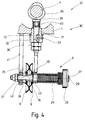
- FIG. 5 differs from that according to FIG. 4 in that the vibration generating device 30 is designed to act directly on the brake actuator 9.
- the push rod 31 is arranged with its axis lying in the central plane between the two brake actuators 9. At the end, it bears an approximately frustoconical drive member 43O which has a flat base surface 44 approximately parallel to the bearing axis 29, the longitudinal extent of which in the direction of the bearing axis 29 is dimensioned such that it overlaps the two brake actuators 9 on both sides in the manner shown in FIG.
- the brake actuators 9 are mounted on the intermediate bush 23 with radial play, their radial distance from the base surface 44 of the drive element 43 being dimensioned such that the drive element 43 periodically engages the circumference of the brake actuator 9 during the reciprocating movement of the push rod 31 and thus set them into oscillatory movements, the amplitudes of which are directed essentially at right angles to the bearing axis 29.
- the guide pin 19 is rigidly screwed to the bracket 41 in this case.
- the guide pin 19 is supported by means of a rubber-elastic bearing part 42 according to FIG. 3.
- the guide pin 29 may also consist of an elastic material.
- the compression spring 26 can also be replaced by other loading means, for example an electromagnet or means under the influence of gravity. Examples of this will be explained below with reference to the embodiments according to FIGS. 6 to 11.
- the two brake actuators 9 are placed on an elongated guide element in the form of the guide bolt 19 containing the common bearing axis 29, in the embodiments according to FIGS. 6 to 14 there is a guide element 190 used, which makes it possible to dispense with a continuous guide pin 19.
- a lint deposit When braking heavily fluffing yarns, namely, a lint deposit can build up in the area of the guide pin 19 or the intermediate bush 23 (FIG. 3) pushed onto it, because here there is a deflection point for the running thread 10 in the manner shown in FIG. 1.
- a lint deposit around the intermediate bush 23 can gradually lead to the complete blocking of the rotary movement of the brake actuator 9.
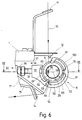
- Each of the bow-shaped bearing elements 5O carries three integrally formed, radially inwardly projecting bearing projections 52, 53, 54, which are distributed along the circumference at approximately equal angular intervals and of which the bearing projection 53 lies approximately in the extension of the axial direction of the push rod 31.
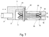
- the bearing projections 52 to 54 form, as can be seen from FIG. 7, discrete, locally limited, lateral support points for the two brake actuators 9, so that these are held captively in the guide element 19O.
- Radially, the two brake actuators 9 are supported on their circumference at two bearing points 55, 56 which are arranged in the region of the bearing projections 53, 54.
- the guide element 19O is usually made of plastic material; it has radial clearances 61 between the bearing projections 52 to 54 in the manner shown in FIG. 6, which extend over most of the circumference of the brake discs 9 and are thus also conducive to easy fluff removal.
- the thread path is chosen by appropriate arrangement of the thread eyelet 11 of the cross pin 62 and the thread deflecting pin 64 such that the between the Brake actuator 9 incoming thread 10 (left in FIG. 6) runs in at a distance next to the common bearing axis 29 and exits between them in the region of the lower bearing point 56. Due to this eccentric thread travel, a torque is frictionally applied to the two brake plates 9 by the running thread 10, which acts in the same direction of rotation, indicated by the arrow 59, as the torque which is generated by the vibration generating device 30 via the push rod 31 on the brake discs 9 is transmitted.
- the compression spring 26 is also omitted.
- the two brake actuators 9 are pressed axially against one another by magnetic forces.
- ring-shaped, counter-pole permanent magnets 65 are glued onto the brake disks 9 made of non-magnetic material, which axially press the two brake disks 9 (FIG. 7), which are approximately shell-shaped in cross section, against one another with a predetermined force.
- the embodiment according to FIG. 8 corresponds to the embodiment of the thread brake 8 described above with reference to FIGS. 6, 7 in all parts, with the exception that the transverse pin 62 in the through openings 59 on the other, the right side of the common bearing axis 29 is misplaced.
- the thread 10 carried out off-center between the brake actuators 9 thus exerts a torque on the brake actuators 9 in the run, the direction of which is indicated by the arrow 58a and opposite to the direction of this torque in the embodiment according to FIG. 6.
- FIGS. 9 to 14 Corresponding embodiments of the thread brake 8 are illustrated in FIGS. 9 to 14: The embodiment according to FIG. 9 essentially corresponds to the embodiments according to FIGS. 6,8; Identical parts are given the same reference symbols and are not explained again.
- the thread 10 running in between the brake actuators 9 from above on the circumferential side is led out through the opening 59 on one side from the space between the two brake actuators 9; it then goes on the outside of the guide element 19O via the thread deflecting pin 64 to the thread inlet eyelet 14.
- a brake actuator 9a is fixedly arranged on the mounting block 51 of the guide element 19O assigned to it.
- the guide element 19O is provided with a projecting, integrally formed projection 66, to which the annular brake disk 9a is attached.
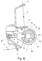
- This brake disc 9a is provided at a point lying outside the thread travel path shown in FIGS. 10, 11 with a V-shaped thread insertion slot 67 leading from the circumference into the opening 59.
- the threading process proceeds in such a way that the thread 1O is pulled beyond the knot catcher 12 and a thread limiting hook 12O assigned to it into the area below the thread brake 8 and then without releasing it radially from the side (right in FIG. 7) between introduces the two bearing elements 50 between the two brake disks 9, 9a.
- the thread 1O over the Thread insertion opening 67 is led laterally out of the central opening 59 of the fixed brake disc 9a and then threaded through the thread eyelet 14.
- the thread 10 thus leaves the opening 59 in the manner shown in FIG. 10, whereby it runs over its correspondingly rounded edge.
- the latter preferably consists of ceramic or a correspondingly wear-resistant coated material.
- annular permanent magnets 65 according to FIG. 6, the annular permanent magnet 65a of the fixed brake disk 9a having a corresponding cutout because of the thread insertion slot 67.
- the fixed brake actuator 9a is ring-shaped with a continuous central opening 59.
- the threading process for the thread 10 is carried out in the manner described with reference to FIGS. 10, 11.
- the second rotatably mounted brake actuator 9 is not provided with a central opening 59, but rather is closed in the center (see FIG. 14).
- the brake actuator 9 carries an integrally formed, cylindrical bearing extension 68 containing the common bearing axis 29, with which it is mounted on an arm-like support 69 so that it can rotate freely with play.
- the carrier 69 is in turn supported at the other end by a bearing fork 70 against the mounting block 51 of the guide element 19O. It is under the action of a compression spring 71 which is placed on a threaded bolt 72 inserted into the mounting block 51 and the pretension of which can be appropriately adjusted in a known manner by means of a control nut 73.
- the control nut 72 By adjusting the control nut 72 accordingly, the braking force exerted by the brake actuators 9, 9a on the continuous thread 10 can be adjusted.
Landscapes
- Engineering & Computer Science (AREA)
- Textile Engineering (AREA)
- Knitting Machines (AREA)
- Braking Arrangements (AREA)
- Tension Adjustment In Filamentary Materials (AREA)
- Transmission Devices (AREA)
- Auxiliary Weaving Apparatuses, Weavers' Tools, And Shuttles (AREA)
- Looms (AREA)
- Clamps And Clips (AREA)
- Connection Of Motors, Electrical Generators, Mechanical Devices, And The Like (AREA)
Applications Claiming Priority (2)
| Application Number | Priority Date | Filing Date | Title |
|---|---|---|---|
| DE4104663A DE4104663C1 (fr) | 1991-02-15 | 1991-02-15 | |
| DE4104663 | 1991-02-15 |
Publications (2)
| Publication Number | Publication Date |
|---|---|
| EP0499218A1 true EP0499218A1 (fr) | 1992-08-19 |
| EP0499218B1 EP0499218B1 (fr) | 1994-11-30 |
Family
ID=6425112
Family Applications (1)
| Application Number | Title | Priority Date | Filing Date |
|---|---|---|---|
| EP92102286A Expired - Lifetime EP0499218B1 (fr) | 1991-02-15 | 1992-02-12 | Frein de fil |
Country Status (22)
| Country | Link |
|---|---|
| US (1) | US5343983A (fr) |
| EP (1) | EP0499218B1 (fr) |
| JP (1) | JPH0790984B2 (fr) |
| KR (1) | KR970009384B1 (fr) |
| CN (1) | CN1026884C (fr) |
| BR (1) | BR9204772A (fr) |
| CA (1) | CA2076752C (fr) |
| CZ (1) | CZ280298B6 (fr) |
| DE (2) | DE4104663C1 (fr) |
| EG (1) | EG19529A (fr) |
| ES (1) | ES2065081T3 (fr) |
| HK (1) | HK48895A (fr) |
| MX (1) | MX9200657A (fr) |
| MY (1) | MY108137A (fr) |
| PH (1) | PH31514A (fr) |
| RO (1) | RO109628B1 (fr) |
| RU (1) | RU2070863C1 (fr) |
| SG (1) | SG30559G (fr) |
| SK (1) | SK281015B6 (fr) |
| TR (1) | TR25972A (fr) |
| UA (1) | UA25896C2 (fr) |
| WO (1) | WO1992014670A1 (fr) |
Cited By (5)
| Publication number | Priority date | Publication date | Assignee | Title |
|---|---|---|---|---|
| GB2274469A (en) * | 1993-01-21 | 1994-07-27 | Memminger Iro Gmbh | Thread brake |
| DE4409450A1 (de) * | 1994-03-18 | 1995-09-21 | Memminger Iro Gmbh | Fadenbremseinrichtung |
| DE19531579C1 (de) * | 1995-08-28 | 1997-01-23 | Barth Tex Instr & Software Gmb | Fadenbremse |
| WO2013138944A1 (fr) * | 2012-03-21 | 2013-09-26 | Uster Technologies Ag | Tendeur de fil à disques comprenant un dispositif de nettoyage |
| CH706264A1 (de) * | 2012-03-21 | 2013-09-30 | Uster Technologies Ag | Tellerfadenbremse. |
Families Citing this family (19)
| Publication number | Priority date | Publication date | Assignee | Title |
|---|---|---|---|---|
| SE504096C2 (sv) * | 1995-03-02 | 1996-11-11 | F & N Mekanik Ab | Garngripare för garnmatningssystem i vävstolar |
| DE19720795A1 (de) * | 1997-05-16 | 1998-11-19 | Sipra Patent Beteiligung | Fadenbremse und damit ausgerüstete Textilmaschine und Fadenliefervorrichtung |
| DE19733264A1 (de) * | 1997-08-01 | 1999-02-04 | Sipra Patent Beteiligung | Fadenliefervorrichtung und dafür geeignetes Antriebsrad |
| DE19919122A1 (de) * | 1999-04-27 | 2000-11-02 | Iro Patent Ag Baar | Aktuator und Fadenbremse mit einem Aktuator |
| DE10006599A1 (de) * | 2000-02-15 | 2001-08-23 | Memminger Iro Gmbh | Friktionsfournisseur mit Vibrationsanregung |
| US6439488B1 (en) | 2000-11-27 | 2002-08-27 | Bobby Hunter | Tensioning device for circular knitting machine |
| DE10345369A1 (de) | 2003-09-26 | 2005-05-12 | Sipra Patent Beteiligung | Fadenbremse und damit ausgerüstete Textilmaschine und Fadenliefervorrichtung |
| CN102707097B (zh) * | 2011-03-28 | 2015-08-19 | 国家电网公司 | 带有磁吸式连接装置的试验线夹 |
| DE102012103534A1 (de) | 2011-09-21 | 2013-03-21 | Memminger-Iro Gmbh | Vorrichtung zur Zufuhr eines Fadens zu einer Textilmaschine |
| DE102011053824B3 (de) | 2011-09-21 | 2012-10-04 | Memminger-Iro Gmbh | Fadenliefergerät zur Zufuhr eines Fadens zu einer Textilmaschine |
| CN102677383A (zh) * | 2012-06-08 | 2012-09-19 | 慈溪太阳洲纺织科技有限公司 | 一种针织输纱机 |
| CN106149187B (zh) * | 2016-08-03 | 2019-06-21 | 广州美名纺织科技有限公司 | 一种用于针织大圆机的滚轮式夹纱器 |
| CN106637644B (zh) * | 2017-03-16 | 2022-09-16 | 泉州精准机械有限公司 | 一种防缠纱张力调节的送纱器 |
| CN108987098B (zh) * | 2018-08-31 | 2023-12-12 | 公元股份有限公司 | 一种卧式绕线机 |
| CN109487426B (zh) * | 2018-11-02 | 2024-04-12 | 南京曼星忆知科技有限公司 | 一种全电脑织袜机 |
| CN110054023B (zh) * | 2019-05-24 | 2025-02-25 | 晋江市万晋自动化设备有限公司 | 一种独立恒张力弹性线材控制装置 |
| CN111286846B (zh) * | 2020-04-15 | 2021-04-16 | 扬州市郭氏精密机械制造有限公司 | 一种织布用纱夹 |
| EP4101965B1 (fr) * | 2021-06-11 | 2025-01-01 | KARL MAYER STOLL R&D GmbH | Frein de fils |
| US20260015200A1 (en) * | 2024-07-11 | 2026-01-15 | Esten Morgan | Tensioning adapter for weaving machines and methods thereof |
Citations (2)
| Publication number | Priority date | Publication date | Assignee | Title |
|---|---|---|---|---|
| DE2758334A1 (de) * | 1977-12-27 | 1979-07-05 | Schlafhorst & Co W | Fadenbremse |
| DE3828762A1 (de) * | 1988-08-25 | 1990-03-01 | Memminger Gmbh | Selbstreinigende fadenbremse |
Family Cites Families (6)
| Publication number | Priority date | Publication date | Assignee | Title |
|---|---|---|---|---|
| CH584650A5 (fr) * | 1974-09-06 | 1977-02-15 | Peyer Siegfried | |
| CH636578A5 (de) * | 1977-12-27 | 1983-06-15 | Schlafhorst & Co W | Fadenbremse. |
| US4209881A (en) * | 1978-03-21 | 1980-07-01 | Phillips Petroleum Company | Knitting intermittently drawn yarns |
| US4313578A (en) * | 1978-07-27 | 1982-02-02 | Appalachian Electronic Instruments, Inc. | Yarn tension control apparatus |
| DE3029509A1 (de) * | 1980-08-04 | 1982-03-25 | Gütermann & Co, 7809 Gutach | Fadenbremse |
| JPH0252864A (ja) * | 1988-08-17 | 1990-02-22 | Tsudakoma Corp | 繊維機械における糸張力調整装置 |
-
1991
- 1991-02-15 DE DE4104663A patent/DE4104663C1/de not_active Expired - Lifetime
-
1992
- 1992-02-12 DE DE59200816T patent/DE59200816D1/de not_active Expired - Fee Related
- 1992-02-12 BR BR9204772A patent/BR9204772A/pt not_active IP Right Cessation
- 1992-02-12 PH PH43907A patent/PH31514A/en unknown
- 1992-02-12 EP EP92102286A patent/EP0499218B1/fr not_active Expired - Lifetime
- 1992-02-12 RO RO92-01309A patent/RO109628B1/ro unknown
- 1992-02-12 SG SG1995904108A patent/SG30559G/en unknown
- 1992-02-12 JP JP4503918A patent/JPH0790984B2/ja not_active Expired - Fee Related
- 1992-02-12 WO PCT/DE1992/000096 patent/WO1992014670A1/fr not_active Ceased
- 1992-02-12 RU RU9292016310A patent/RU2070863C1/ru not_active IP Right Cessation
- 1992-02-12 CA CA002076752A patent/CA2076752C/fr not_active Expired - Fee Related
- 1992-02-12 US US07/930,656 patent/US5343983A/en not_active Expired - Lifetime
- 1992-02-12 UA UA93004027A patent/UA25896C2/uk unknown
- 1992-02-12 ES ES92102286T patent/ES2065081T3/es not_active Expired - Lifetime
- 1992-02-12 KR KR1019920702541A patent/KR970009384B1/ko not_active Expired - Lifetime
- 1992-02-13 MY MYPI92000230A patent/MY108137A/en unknown
- 1992-02-14 SK SK448-92A patent/SK281015B6/sk unknown
- 1992-02-14 TR TR92/0158A patent/TR25972A/xx unknown
- 1992-02-14 CZ CS92448A patent/CZ280298B6/cs not_active IP Right Cessation
- 1992-02-14 CN CN92101428A patent/CN1026884C/zh not_active Expired - Lifetime
- 1992-02-15 EG EG9192A patent/EG19529A/xx active
- 1992-02-17 MX MX9200657A patent/MX9200657A/es not_active IP Right Cessation
-
1995
- 1995-03-30 HK HK48895A patent/HK48895A/xx not_active IP Right Cessation
Patent Citations (2)
| Publication number | Priority date | Publication date | Assignee | Title |
|---|---|---|---|---|
| DE2758334A1 (de) * | 1977-12-27 | 1979-07-05 | Schlafhorst & Co W | Fadenbremse |
| DE3828762A1 (de) * | 1988-08-25 | 1990-03-01 | Memminger Gmbh | Selbstreinigende fadenbremse |
Cited By (10)
| Publication number | Priority date | Publication date | Assignee | Title |
|---|---|---|---|---|
| GB2274469A (en) * | 1993-01-21 | 1994-07-27 | Memminger Iro Gmbh | Thread brake |
| DE4301507A1 (de) * | 1993-01-21 | 1994-08-11 | Memminger Iro Gmbh | Fadenbremse |
| GB2274469B (en) * | 1993-01-21 | 1996-03-13 | Memminger Iro Gmbh | Thread brake |
| US5782424A (en) * | 1993-01-21 | 1998-07-21 | Memminger-Iro Gmbh | Thread brake |
| DE4409450A1 (de) * | 1994-03-18 | 1995-09-21 | Memminger Iro Gmbh | Fadenbremseinrichtung |
| CN1076707C (zh) * | 1994-03-18 | 2001-12-26 | 梅明格-Iro股份有限公司 | 纱线制动装置 |
| DE19531579C1 (de) * | 1995-08-28 | 1997-01-23 | Barth Tex Instr & Software Gmb | Fadenbremse |
| WO2013138944A1 (fr) * | 2012-03-21 | 2013-09-26 | Uster Technologies Ag | Tendeur de fil à disques comprenant un dispositif de nettoyage |
| CH706264A1 (de) * | 2012-03-21 | 2013-09-30 | Uster Technologies Ag | Tellerfadenbremse. |
| CH706263A1 (de) * | 2012-03-21 | 2013-09-30 | Uster Technologies Ag | Tellerfadenbremse mit Reinigungseinrichtung. |
Also Published As
| Publication number | Publication date |
|---|---|
| TR25972A (tr) | 1993-11-01 |
| SK281015B6 (sk) | 2000-10-09 |
| CA2076752A1 (fr) | 1992-08-16 |
| HK48895A (en) | 1995-04-07 |
| UA25896C2 (uk) | 1999-02-26 |
| US5343983A (en) | 1994-09-06 |
| WO1992014670A1 (fr) | 1992-09-03 |
| RO109628B1 (ro) | 1995-04-28 |
| DE59200816D1 (de) | 1995-01-12 |
| PH31514A (en) | 1998-11-03 |
| CZ280298B6 (cs) | 1995-12-13 |
| CN1026884C (zh) | 1994-12-07 |
| CN1064845A (zh) | 1992-09-30 |
| KR970009384B1 (ko) | 1997-06-12 |
| MX9200657A (es) | 1992-08-01 |
| JPH0790984B2 (ja) | 1995-10-04 |
| EP0499218B1 (fr) | 1994-11-30 |
| CA2076752C (fr) | 1998-04-21 |
| RU2070863C1 (ru) | 1996-12-27 |
| JPH06502613A (ja) | 1994-03-24 |
| DE4104663C1 (fr) | 1992-08-13 |
| EG19529A (en) | 1995-07-27 |
| BR9204772A (pt) | 1993-07-06 |
| ES2065081T3 (es) | 1995-02-01 |
| CS44892A3 (en) | 1992-10-14 |
| MY108137A (en) | 1996-08-15 |
| SG30559G (en) | 1995-09-18 |
Similar Documents
| Publication | Publication Date | Title |
|---|---|---|
| EP0499218B1 (fr) | Frein de fil | |
| DE69132780T2 (de) | Garnliefervorrichtung | |
| CH691904A5 (de) | Vorrichtung zur Einstellung der Spannung eines Fadens. | |
| DE4409450C2 (de) | Fadenbremseinrichtung | |
| DE19720795A1 (de) | Fadenbremse und damit ausgerüstete Textilmaschine und Fadenliefervorrichtung | |
| DE4301507C2 (de) | Fadenbremse | |
| EP0524429A1 (fr) | Dispositif pour freiner distingtivement des fils ou des fils de fers et similaire | |
| DE3505913A1 (de) | Fadenspannvorrichtung an einem spulengatter | |
| CH665658A5 (de) | Vorrichtung zum lagern und antreiben eines spinnrotors einer oe-spinnvorrichtung. | |
| EP0725850B2 (fr) | Dispositif d'amenee du fil pour machines textiles | |
| DE2362481A1 (de) | Regelbare fadenbremsvorrichtung an zettelgattern oder anderen umspulmaschinen | |
| EP0165444B1 (fr) | Entraînement pour dispositif de paraffinage et procédé pour entraîner un tel dispositif | |
| DE3801880C3 (de) | Streckwerk in Spinnereimaschinen, insbesondere Regulierstreckwerk in Strecken | |
| EP3214029B1 (fr) | Dispositif de va-et-vient de fil pour un bobinoir d'une machine textile fabriquant des bobines à fil croisé | |
| EP2199440B1 (fr) | Tendeur de fil à compensation et râtelier porte bobines | |
| DE3327633C2 (de) | Fadenbremsvorrichtung | |
| DE3828762A1 (de) | Selbstreinigende fadenbremse | |
| DE69819861T2 (de) | Vorrichtung zum Liefern eines elastisch ausdehnbaren Fadens zu Strickmaschinen | |
| DE4120328C1 (en) | Self-cleaning yarn brake giving improved cleaning action - has two disc- or plate-shaped brake elements mounted on bearing means and pressed against each other yieldingly through loading means | |
| EP1218275B1 (fr) | Dispositif de freinage de fil | |
| DE2923034C2 (de) | Fadenspannvorrichtung an einem Spulengatter | |
| CH635802A5 (de) | Fadenbremse fuer eine textilmaschine sowie verwendung derselben. | |
| DE10306232A1 (de) | Antriebsvorrichtung für einen Fadenführer zum changierenden Verlegen eines Fadens vor einer Spulvorrichtung | |
| DE1785157C (de) | Vorrichtung zum Durchschneiden eines laufenden Texülgames | |
| DE19522304C1 (de) | Changiervorrichtung an Aufwickelvorrichtungen |
Legal Events
| Date | Code | Title | Description |
|---|---|---|---|
| PUAI | Public reference made under article 153(3) epc to a published international application that has entered the european phase |
Free format text: ORIGINAL CODE: 0009012 |
|
| AK | Designated contracting states |
Kind code of ref document: A1 Designated state(s): DE ES FR GB GR IT PT |
|
| 17P | Request for examination filed |
Effective date: 19930115 |
|
| 17Q | First examination report despatched |
Effective date: 19940505 |
|
| GRAA | (expected) grant |
Free format text: ORIGINAL CODE: 0009210 |
|
| AK | Designated contracting states |
Kind code of ref document: B1 Designated state(s): DE ES FR GB GR IT PT |
|
| ITF | It: translation for a ep patent filed | ||
| ET | Fr: translation filed | ||
| GBT | Gb: translation of ep patent filed (gb section 77(6)(a)/1977) |
Effective date: 19941208 |
|
| REF | Corresponds to: |
Ref document number: 59200816 Country of ref document: DE Date of ref document: 19950112 |
|
| REG | Reference to a national code |
Ref country code: ES Ref legal event code: FG2A Ref document number: 2065081 Country of ref document: ES Kind code of ref document: T3 |
|
| REG | Reference to a national code |
Ref country code: GR Ref legal event code: FG4A Free format text: 3014845 |
|
| SC4A | Pt: translation is available |
Free format text: 941205 AVAILABILITY OF NATIONAL TRANSLATION |
|
| PLBE | No opposition filed within time limit |
Free format text: ORIGINAL CODE: 0009261 |
|
| STAA | Information on the status of an ep patent application or granted ep patent |
Free format text: STATUS: NO OPPOSITION FILED WITHIN TIME LIMIT |
|
| 26N | No opposition filed | ||
| REG | Reference to a national code |
Ref country code: GB Ref legal event code: IF02 |
|
| PGFP | Annual fee paid to national office [announced via postgrant information from national office to epo] |
Ref country code: GB Payment date: 20050128 Year of fee payment: 14 |
|
| PGFP | Annual fee paid to national office [announced via postgrant information from national office to epo] |
Ref country code: PT Payment date: 20050214 Year of fee payment: 14 |
|
| PGFP | Annual fee paid to national office [announced via postgrant information from national office to epo] |
Ref country code: FR Payment date: 20050216 Year of fee payment: 14 |
|
| PGFP | Annual fee paid to national office [announced via postgrant information from national office to epo] |
Ref country code: GR Payment date: 20050222 Year of fee payment: 14 |
|
| PG25 | Lapsed in a contracting state [announced via postgrant information from national office to epo] |
Ref country code: GB Free format text: LAPSE BECAUSE OF NON-PAYMENT OF DUE FEES Effective date: 20060212 |
|
| PGFP | Annual fee paid to national office [announced via postgrant information from national office to epo] |
Ref country code: ES Payment date: 20060220 Year of fee payment: 15 |
|
| PG25 | Lapsed in a contracting state [announced via postgrant information from national office to epo] |
Ref country code: PT Free format text: LAPSE BECAUSE OF NON-PAYMENT OF DUE FEES Effective date: 20060814 |
|
| GBPC | Gb: european patent ceased through non-payment of renewal fee |
Effective date: 20060212 |
|
| REG | Reference to a national code |
Ref country code: PT Ref legal event code: MM4A Effective date: 20060814 |
|
| REG | Reference to a national code |
Ref country code: FR Ref legal event code: ST Effective date: 20061031 |
|
| PG25 | Lapsed in a contracting state [announced via postgrant information from national office to epo] |
Ref country code: FR Free format text: LAPSE BECAUSE OF NON-PAYMENT OF DUE FEES Effective date: 20060228 |
|
| REG | Reference to a national code |
Ref country code: ES Ref legal event code: FD2A Effective date: 20070213 |
|
| PG25 | Lapsed in a contracting state [announced via postgrant information from national office to epo] |
Ref country code: ES Free format text: LAPSE BECAUSE OF NON-PAYMENT OF DUE FEES Effective date: 20070213 |
|
| PG25 | Lapsed in a contracting state [announced via postgrant information from national office to epo] |
Ref country code: GR Free format text: LAPSE BECAUSE OF NON-PAYMENT OF DUE FEES Effective date: 20060904 |
|
| PGFP | Annual fee paid to national office [announced via postgrant information from national office to epo] |
Ref country code: DE Payment date: 20090428 Year of fee payment: 18 |
|
| PG25 | Lapsed in a contracting state [announced via postgrant information from national office to epo] |
Ref country code: DE Free format text: LAPSE BECAUSE OF NON-PAYMENT OF DUE FEES Effective date: 20100901 |
|
| PGFP | Annual fee paid to national office [announced via postgrant information from national office to epo] |
Ref country code: IT Payment date: 20110226 Year of fee payment: 20 |