EP0499296A2 - Sections emboîtables pour planchers portables et semblable - Google Patents
Sections emboîtables pour planchers portables et semblable Download PDFInfo
- Publication number
- EP0499296A2 EP0499296A2 EP92108191A EP92108191A EP0499296A2 EP 0499296 A2 EP0499296 A2 EP 0499296A2 EP 92108191 A EP92108191 A EP 92108191A EP 92108191 A EP92108191 A EP 92108191A EP 0499296 A2 EP0499296 A2 EP 0499296A2
- Authority
- EP
- European Patent Office
- Prior art keywords
- edge
- edges
- sections
- locking members
- floor
- Prior art date
- Legal status (The legal status is an assumption and is not a legal conclusion. Google has not performed a legal analysis and makes no representation as to the accuracy of the status listed.)
- Withdrawn
Links
Images


Classifications
-
- E—FIXED CONSTRUCTIONS
- E05—LOCKS; KEYS; WINDOW OR DOOR FITTINGS; SAFES
- E05B—LOCKS; ACCESSORIES THEREFOR; HANDCUFFS
- E05B65/00—Locks or fastenings for special use
- E05B65/08—Locks or fastenings for special use for sliding wings
- E05B65/087—Locks or fastenings for special use for sliding wings the bolts sliding parallel to the wings
-
- E—FIXED CONSTRUCTIONS
- E04—BUILDING
- E04F—FINISHING WORK ON BUILDINGS, e.g. STAIRS, FLOORS
- E04F15/00—Flooring
- E04F15/02—Flooring or floor layers composed of a number of similar elements
- E04F15/024—Sectional false floors, e.g. computer floors
- E04F15/02405—Floor panels
-
- E—FIXED CONSTRUCTIONS
- E04—BUILDING
- E04F—FINISHING WORK ON BUILDINGS, e.g. STAIRS, FLOORS
- E04F15/00—Flooring
- E04F15/02—Flooring or floor layers composed of a number of similar elements
- E04F15/04—Flooring or floor layers composed of a number of similar elements only of wood or with a top layer of wood, e.g. with wooden or metal connecting members
-
- E—FIXED CONSTRUCTIONS
- E04—BUILDING
- E04F—FINISHING WORK ON BUILDINGS, e.g. STAIRS, FLOORS
- E04F2201/00—Joining sheets or plates or panels
- E04F2201/01—Joining sheets, plates or panels with edges in abutting relationship
- E04F2201/0107—Joining sheets, plates or panels with edges in abutting relationship by moving the sheets, plates or panels substantially in their own plane, perpendicular to the abutting edges
- E04F2201/0115—Joining sheets, plates or panels with edges in abutting relationship by moving the sheets, plates or panels substantially in their own plane, perpendicular to the abutting edges with snap action of the edge connectors
-
- E—FIXED CONSTRUCTIONS
- E04—BUILDING
- E04F—FINISHING WORK ON BUILDINGS, e.g. STAIRS, FLOORS
- E04F2201/00—Joining sheets or plates or panels
- E04F2201/05—Separate connectors or inserts, e.g. pegs, pins, keys or strips
Definitions
- This invention relates generally to interconnectable sections and improved locking means therefor whereby sections can be secured together in edge-to-edge relationship.
- Examples include interlocking floor sections for a portable floor which can be assembled together to form an extended floor area, or which can be taken apart for storage.
- Portable floors consisting of a number of interlocking sections, are used for providing a temporary hard surface floor which may be set up over carpeting or other surfaces on a temporary basis by joining a number of floor sections together in edge-to-edge relationship.
- Locking or connecting means are provided along the edges to secure adjacent sections together during use. For storage, the locking means are released or otherwise disconnected so that the sections can be disassembled for storage.
- One feature of the present invention is the provision of an improved locking means for connection of such sections. While the locking means of this invention is applicable to edge-to-edge joining of interlocking panels or sections for a wide variety of purposes, since the presently preferred embodiment of the invention is in connection with portable floors, the specification and drawings in this patent application are directed to that particular use.
- a locking device used for edge-to-edge connection is disclosed in AU-B 486 349.
- Portable floors are used, for example, in the hospitality and entertainment industries when it is desired to temporarily provide a smooth hard surface for dancing or other activities.
- Portable floors may be set up over carpeted floor or other surfaces by connecting together in edge-to-edge fashion a plurality of floor sections. The sections are releasably locked together along their edges to produce an extended floor area of the desired size.
- a portable floor of this general type is disclosed in U.S. Patent No. 3,310,919, assigned to the assignee of the present invention.
- floor panels are provided, each having a metallic tongue section along certain edges and a metallic groove section along certain other edge, such that adjoining sections can be fitted together in edge-to-edge relationship by tongue-and-groove arrangement, and held in place by locking screws threaded through to engage notches in the tongue members. While the portable floor disclosed in that patent has been successful in providing a convenient and efficient portable floor, the present invention provides an improved interlock system and construction which are believed to be advantageous.
- an interlocking means must meet a number of rather stringent criteria.
- the locks must reliably and positively engage when sections are pushed together, so that there will be no possibility of sections which "look" locked but which in fact are not.
- the locking means must operate reliably under adverse conditions, including operating for year after year despite the probability that dust, dirt and other debris will work itself into the lock, and despite predictable rough handling and even abuse during the operations of setting up and taking down the floor.
- an improved locking mechanism including first and second members which fit together for locking purposes.
- the second lock member has pins mounted therein for motion along defined paths between first and second positions, referred to herein as closed and open positions.
- Means, for example resilient means, are provided for normally urging the pins to their closed positions.
- the first lock member has means for moving the pins to their open positions when the two lock members are moved together, and for permitting the pins to return to their closed positions after engagement of the first and second lock members.
- the first lock member has engagement surfaces which contact the pins when forces are applied to move the first and second lock members apart.
- the shape or slope of these engagement surfaces relative to the paths of defined motion of the pins is such as to cause substantial interference of the first lock member with the pins which prevents movement of the pins to their open position and therefore prevents removal of the lock member.
- a separate locking mechanism is provided to move the pins to their open position and thereby permit disengagement of the mechanism.
- the first lock member includes a flange and the second lock member includes means defining a recess to receive the flange.
- the pins are positioned generally within the receiving space, and the flange includes surfaces on its outer edge for moving the pins to their open position, and hook-like portions having the engagement surfaces which engage the pins in the locked position.
- an improved panel construction in which a panel is formed in a single molding process which encapsulates a core member in urethane, molds the edge tongue and groove portions with recesses formed therein to receive the locking members, and bonds the decorative and durable floor surface.
- a preferred application of the locking means of the present invention is in the edge-to-edge locking mechanism for interlocking floor sections for a portable floor.
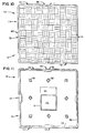
- an improved floor section according to one aspect of the invention, with which the locking mechanism may be used will be described with reference to Figs. 10-14.
- floor section 10 is a square, flat panel. It will be understood, however, that a square configuration is not required, but that a rectangular or other polygonal form could be used; however, a square section is believed to be preferable in terms of ease of used and manufacture.
- Section 10 has edges designated 11a, 11b, 11c and 11d, respectively. Edges 11a and 11b are tongue-type edges which would include first locking members, and edges 11c and 11d are groove-type edges which would include second locking members.
- the tongue and the groove edges are complementary to one another, as are the first and second locking members, so that a plurality of panels such as the one in Fig. 10 can be connected together in edge-to-edge relationship, with tongue sections connecting with groove sections, and with the first and second locking members locked together as described hereinafter.
- a floor section 10 includes a core 12 which is a flat, square panel of approximately the same dimensions as the floor section.
- Core 12 is preferably made of wood, such as particle board or plywood, although other materials could be used.
- Core 12 is completely embedded in a urethane-type plastic material 15, in a molding process described below, which encapsulates core 12 and forms the edges of the floor section 10. Complete encapsulation prevents the wood core from absorbing moisture.
- lamination sheet 13 is bonded to the urethane. This sheet covers substantially the entire upper surface of floor section 10, except for a band or strip of the urethane material adjacent the edges.
- Lamination 13 is a high-pressure laminate material having a durable wear surface, which also may contain a decorative pattern such as the parquet pattern indicated in Fig. 10.
- Laminate 13 has a sanded or roughened back side for maximum adherence to the urethane.
- a backer sheet 14 which is also bonded to the urethane.
- This sheet may also be a high-pressure laminate material similar to laminate 13, and provides additional strength and stiffness for the panel as well as helping to resist any warpage.
- the edges are formed integrally with the urethane 15 which encapsulates core 12.
- Groove-type edges 11c or 11d as seen in the cross-sectional view of Fig. 12 are formed with upper and lower edges 21, 22, respectively, and a groove portion 23 formed therebetween.
- Lower surface 24 adjacent edge 22 forms a strip or band along the edge far contacting the underlying floor or other surface upon which floor section 10 is placed.
- Lower surface 24 extends only a certain distance inwardly from the edge where the contour of the urethane material slopes up to the level of backer sheet 14, forming a recess or hollowed-out area 29 which extends over most of the back side of floor section 10.
- a number of supports 30 are spaced at intervals around the underside of the floor section, in the form of areas where the urethane material extends down from backer sheet 14 to the level of lower surface 24, to provide floor or ground engagement and additional support.
- these supports 30 are in the form of diamond-shaped walled structures, but it will be understood that any size, shape and spacing arrangement can be used.
- a central support 31 is provided in the form of a roughly rectangular walled structure which also extends to the ground engagement level of lower surface 24.
- an interior recess 32 is provided within central support 31, and this forms a convenient place for gluing on an instruction data sheet.
- a wider support portion 32 of support 31 provides a surface on which a logo or other information (not shown) may be molded in.
- tongue-type edges 11a or 11b are shown in cross-section.
- the edges of top laminate 13, core 12 and backer sheet 14 are seen encapsulated in the urethane material 15, as in the case of the groove-type section.
- the tongue-type section of Fig. 13 has a large projection 25 formed and sized to be received in groove portion 23.
- a lower surface 26 is formed adjacent projection 25, and is at the same level as, and performs the same function as, surface 24 of the groove-type edges.
- Fig. 14 shows a groove-type edge and a tongue-type edge of two adjoining sections engaged together.
- This tongue-and-groove arrangement helps provide a degree of stability and security between adjacent sections, in that it substantially prevents relative up and down movements at the edges.
- Zones 35 are molded in along the midpoints along tongue-type edges 11a and 11b. These zones have a recess for receiving the male lock member, described below. At the midpoints along groove-type edges 11c and 11d, receiving zones 37 are formed in the molded urethane edge to receive the female lock sections described below. Threaded inserts 40 (see Fig. 2) are imbedded in the urethane in the recesses to provide a means for securing the lock members.
- Laminate tope 13 is placed face down in a suitably designed mold (not shown), and core 12 is placed on top of it, separated by spacers (not shown) to allow the urethane material to flow between lamination 13 and core 12.
- Backer sheet 14 is placed above core 12, also separated by spacers so that urethane will flow between the backer and the core.
- the mold is then closed and the urethane material is injected.
- the molten urethane material fills between the top laminate, core and backer, and forms the edges and supports for the floor section.
- UrylonTM brand urethane material from Urylon Development, Inc. Conyers, GA, is used, but other types of urethane or other plastic materials can be used, the selection being made according to desired physical and mechanical properties.
- male-type and female-type locking members are provided, and are mounted preferably at the midpoint along the edges of a floor section in zones 35 and 37, respectively.
- male-type locking members are mounted in the tongue-type edges 11a, 11b and female locking members are mounted in the groove-type edges 11c, 11d.
- two adjacent panels 10a and 10b are positioned with their edges adjacent one another for locking together.
- tongue-type edge 11a of panel 10a and groove-type edge 11c of panel 10b are opposite one another.
- Edge 11a includes a male locking member 50
- groove-type edge 11c includes a female locking mechanism 70.
- a tongue 25 has a gap between the zones indicated by 25a and 25b, and a portion of the core in between may also be cut away to receive lock member 50.
- a portion of edge 11c has a gap to receive female lock portion 70.
- the groove between zones indicated at 22a and 22b has a gap, and a corresponding portion of the core may be cut back to form the recess for receiving lock mechanism 70.
- these gaps or recesses in the edges for receiving the lock members are molded in at the time the panels is made. Alternatively, they could be cut away as by a machining process to form the recesses. This latter process would be preferred if a conventional type panel were used which had aluminum extrusions for the tongue-and-groove edges.
- male lock member 50 generally includes a base portion 51 and a flange portion 60.
- the entire male lock member 50 is preferably made from an integral piece of a strong material such as stainless steel by a machining process, or of other material by a powdered metal molding or casting process.
- the base portion is an elongate generally rectangular member designed to fit into the recess formed in edge 11a for that purpose.
- a pair of mounting holes 52 are provided on either side by means of which screws can be used to secure the male lock member to the threaded inserts 40 of the panel (see Fig. 2).
- Integral flange portion 60 extends perpendicularly from base portion 51, generally in the plane of the floor section itself.
- Flange 60 is thinner than base 51, and is somewhat thicker at its root portion 61 than at its forward edges 62a and 62b. These edges slant backwardly at an angle with respect to the edge of the panel. Between forward edges 62a and 62b is a notch 63 which provides clearance for the release mechanism, as explained below. Formed on either side of flange 60 are hook portions 64a, 64b which cut inwardly on flange 60 and which have engagement surfaces 65a, 65b.
- Female lock member 70 is positioned to fit within a recess formed in edge 11c of the floor section.
- Female lock member 70 may be made from the same materials and processes as described above for member 50.
- Member 70 is in the form of two halves 71, 72 joined together.
- halves 71 and 72 can be identical, so that when one is reversed with respect to the other, they will mate to form the frame or shell for the female lock member 70.
- Lock member 70 includes a large central slot or recess 85 which is adapted to receive flange 60 of the male lock member 50.
- Fig. 15 One of the halves of female lock portion 70 is shown in Fig. 15. Specifically, half 71 is shown from the inside, i.e., from the side facing inwardly to slot or recess 85.
- the female lock member and its two halves have tab or extension portions 79 at each end thereof. Holes 73 are formed therein which receive screws which mate with the threaded inserts 40 (Fig. 2) to hold the lock member in the floor panel.
- a pin 76 and a hole 74 which may be beveled or counter-sunk at its outside.
- a hole 77 and a hole 75 At the other end in corresponding positions are a hole 77 and a hole 75.
- the two halves 71,72 are put together by inserting the alignment pin 76 of each half in the mating hole 77 of the other half.
- the two halves are secured together with screws fitting through holes 74-75.
- a pair of pins or rollers 80a, 80b are positioned within recess 85 generally in a position to be contacted by flange 60 when it is inserted into the lock position.
- Ends 80a, 80b are small cylindrical metallic pieces mounted with their axes transverse to the plane of the floor, and they are positioned within slots 81a, 81b formed in the top and bottom members 71, 72 of the lock member 70. These slots run at angles with respect to the direction of the edge of the floor section, the significance of which angle is discussed further below. These slots define paths of permitted travel of pins 80a, 80b therealong.
- Female lock member 70 also includes springs 90,91 positioned along the back side thereof.
- spring 90 includes a back portion 92 which extends along the back of lock member 70 over screw hole 73, and it may be secured thereto by the screw passing through hole 73 which holds the lock member into the floor section.
- Spring 90 also includes a tip portion 94 which extends slightly beyond the midpoint of the length of the back side of lock member 70.
- Spring 90 also, includes side portions 96a, 96b which are connected to, or are integrally formed with, spring 90, and which extend as plate-like members along either side of lock member 70 generally over the are which includes slot 81a.
- lock member 70 In order to keep the thickness of lock member 70 to a minimum so that it can fit easily within a recess formed in the edge of the floor section, the side portions of member, 71, 72 of lock member 70 have reduced thickness zones to receive portion 96a, 96b of spring 90.
- Side portions 96a, 96b have slots 100a formed therein generally in the area over slots 81a, but running at a different angle, the significance of which angle is explained further below in the operations section.
- the widths of slots 81a, 81b are wider than the width of slots 100a, 100b and pins 80a, 80b have a reduced diameter extension on either end of a diameter corresponding to the width of slots 100a, 100b.
- the main body of pins 80a, 80b have a diameter corresponding to slots 81a, 81b. with pins 80a, 80b received in slots 81a,81b, and the reduced diameter end extensions thereof received in slots 100a, 100b, the pins are retained axially and prevented from falling out of the slots. Motion of pins 80a, 80b in slots 81a, 81b is also dependent upon the flexing of springs 90, 91 so that slots 100a, 100b move to track slots 81a, 81b, as the pins move.
- spring 91 similarly has a back portion 93 which is secured to the lock mechanism by the bolt passing through hole 73, and a tip 95 extends beyond the midpoint of the member and overlays a tip portion of spring 90.
- Tip 95 has a slot formed therein so that tip 94 can pass through tip 95 when both springs are flexed back as indicated, for example, in Fig. 4.
- Members 71, 72 also have slots 110 at their midpoints, the slot extending transverse to the direction of the floor section edge. This slot retains the release cam 121 which is used to unlock the latch.
- each side 71, 72 has a pin 111 adjacent slot 110.
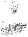
- the release mechanism 120 includes a cam member 121, seen in enlarged detail in Fig. 3.
- Cam member 121 is made of metal or other durable material and is generally flat and of a thickness to fit within slot 85 between the halves 71, 72 of the female lock member, except for a collar portion 122 which extends above the plane of cam member 121 so that it may fit in slot 110.
- a similar collar (not shown in Fig.
- Cam member 121 is on the opposite side of cam member 121, and fits in the corresponding slot 110 (not shown in Fig. 1) for the lower member 72 of lock member 70.
- Cam member 121 has a tip portion 123 which is somewhat elongated, but with a rounded end, for engaging the springs of the lock mechanism, specifically the tip portion 94 of spring 90.
- Cam member 121 also has a flat surface 124, and three surfaces 125, 126, 127. The angle between surfaces 125-126, and between 126-127 corresponds to the angle of the side surfaces of notch 63 of flange 60 of the male lock member 50, which abuts them in various positions.
- Collar 122 is generally cylindrical with diameter corresponding to the width of slot 110, except for protrusion 128 which is too big for the width of slot 110 and therefore limits the rotation of cam member 121 to approximately 90°, as can he seen in Figs. 6-8.
- Collar 122 has a hex opening 129 for an Allen key wrench.
- Cam member 121 has a reduced thickness zone with an edge defining cam surface 131. On the opposite side from that shown in Fig. 3, cam member 121 has another reduced thickness zone with an edge defining surface 132.
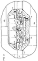
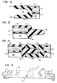
- springs 90, 91 Prior to engagement of the lock members, springs 90, 91 are in the position shown in Fig. 1, which holds pins 80a, 80b generally in their inward position, as shown in Fig. 1
- Cam member 121 of the release mechanism 120 is rotated counter-clockwise, as seen in Fig. 1 (although it would be clockwise if one were to look at the other, or bottom, side of the lock member) with flat surface 124 being positioned parallel to the back edge of the female lock member 70 and in contact with the tip 94 of spring 90, which holds the cam member in that position.
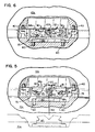
- Fig. 1, and also Fig. 5, show arrows 150 suggesting movement of the lock members 50, 70 directly toward one another, i.e., in a direction perpendicular to the direction of the edges 11a, 11c of the floor sections.
- the members can be brought together in this direction and will latch, as explained below.
- the members can be brought into engagement by pushing them together with at an angle as suggested by arrow 155 in Fig. 1. This is important, for example, when a number of floor sections have already been put together and another floor section is moved into position into a corner created by two adjacent sections, so that, for example, both sides 11a and 11d and their corresponding male and female lock sections would have to engage at the same time.
- the new section would be slid into position with its edges generally parallel to the edges of existing floor sections, but the final motion sliding it into place would be such as to bring the lock sections together at an approximately 45° angle.
- the locking mechanism of this invention will accommodate engagement straight ahead, or at a 45° angle from either side.
- flange 60 As male lock member 50 is moved into engagement with female lock member 70, flange 60 is received in slot 85. Forward edges 62a, 62b of flange 60 engage pins 80a, 80b, respectively, and due to the angles and slopes of edges 62a, 62b and slots 81a, 81b, pins 80a, 80b are moved outwardly and rearwardly along their defined paths of travel in the slots. To do this, springs 90, 91 must flex so that slots 100a, 100b in the springs will track the progress of pins 80a, 80b in slots 81a, 81b. This condition is shown in Fig.
- engagement surfaces 65a, 65b are chosen to be a very small angle with respect to the angel with respect to the angle of orientation of slots 81a, 81b. In the preferred embodiment, this is approximately 10°. Specifically, in the preferred embodiment the angle A (Fig.
- the general sturdiness of the lock members and flange 60 is such that the floor sections can tolerate a considerable amount of abuse, such as attempted lifting of a floor section from one side, while its lock on the other side is still engaged to an adjacent floor section.
- the wrench can be removed and the mechanism will stay in the position shown. It is not entirely stable in this position, but is held there as long as the two floor sections are still positioned together and the notch of flange 60 is bearing on surfaces 125 and 126 of cam member 121. Since the two pins 80a, 80b are in their retracted or open position, the two floor sections can be moved apart. When this happens, as indicated in Fig. 8, the cam member 121 initially moves outward in its slot 110 to follow flange 60 of the male lock member as it is being withdrawn.
- cam member 121 After the hook portions 64a, 64b clear the retracted pins 80a, 80b, further separation of the male and female lock members and movement of cam member 121 causes cam surface 131 (Fig. 3) to engage pin 111 of section 71 of the female lock member (Fig. 15). This causes cam member 121 to pivot slightly in a clockwise direction, as seen in Fig. 8, and the force of springs 90, 91 pushes cam member 121 to the release position shown in Fig. 9. In that position, pin 111 of half 72 of the female lock mechanism may abut surface 132 of cam member 121 to prevent it from rotating further than the position shown in Fig. 9. This prevents the tip 123 from rotating down into the slot or recess 85 where it would interfere with entry of the flange 60. In the position shown in Fig. 9, the cam member and springs have been returned to their normal position, causing pins 80a, 80b to move inwardly, and the lock is ready to receive a flange 60 for the next locking operation.
- ramp-like edge members can be provided with male or female type locking members, so that the edge members can be attached to the edges of floor sections at the edge of an extended floor are, to provide a gradual transition from the underlying floor surface to the level of the top of the portable floor surface, as is generally known.
Landscapes
- Engineering & Computer Science (AREA)
- Architecture (AREA)
- Civil Engineering (AREA)
- Structural Engineering (AREA)
- General Engineering & Computer Science (AREA)
- Life Sciences & Earth Sciences (AREA)
- Wood Science & Technology (AREA)
- Floor Finish (AREA)
Priority Applications (1)
| Application Number | Priority Date | Filing Date | Title |
|---|---|---|---|
| EP19920108191 EP0499296A3 (en) | 1988-07-08 | 1989-06-28 | Interlocking sections for portable floors and the like |
Applications Claiming Priority (3)
| Application Number | Priority Date | Filing Date | Title |
|---|---|---|---|
| US21681888A | 1988-07-08 | 1988-07-08 | |
| US216818 | 1988-07-08 | ||
| EP19920108191 EP0499296A3 (en) | 1988-07-08 | 1989-06-28 | Interlocking sections for portable floors and the like |
Related Parent Applications (1)
| Application Number | Title | Priority Date | Filing Date |
|---|---|---|---|
| EP89908291.1 Division | 1989-06-28 |
Publications (2)
| Publication Number | Publication Date |
|---|---|
| EP0499296A2 true EP0499296A2 (fr) | 1992-08-19 |
| EP0499296A3 EP0499296A3 (en) | 1993-01-27 |
Family
ID=26130920
Family Applications (1)
| Application Number | Title | Priority Date | Filing Date |
|---|---|---|---|
| EP19920108191 Withdrawn EP0499296A3 (en) | 1988-07-08 | 1989-06-28 | Interlocking sections for portable floors and the like |
Country Status (1)
| Country | Link |
|---|---|
| EP (1) | EP0499296A3 (fr) |
Cited By (1)
| Publication number | Priority date | Publication date | Assignee | Title |
|---|---|---|---|---|
| AT519593A1 (de) * | 2017-01-18 | 2018-08-15 | Facc Ag | Verriegelungsvorrichtung |
Citations (2)
| Publication number | Priority date | Publication date | Assignee | Title |
|---|---|---|---|---|
| US3310919A (en) | 1964-10-02 | 1967-03-28 | Sico Inc | Portable floor |
| AU486349B2 (en) | 1973-09-21 | 1976-03-11 | Whiton Hardware Manufacturing Co. Pty. Ltd | Lock |
Family Cites Families (5)
| Publication number | Priority date | Publication date | Assignee | Title |
|---|---|---|---|---|
| US2019692A (en) * | 1934-06-18 | 1935-11-05 | Herbert B Mueller | Portable dance floor or mat |
| US2102086A (en) * | 1936-12-24 | 1937-12-14 | Herbert B Mueller | Portable dance floor |
| US2834065A (en) * | 1953-03-06 | 1958-05-13 | Herbert B Mueller | Portable, reversible dance floor |
| FR1347862A (fr) * | 1962-11-22 | 1964-01-04 | P Picard & Cie Denommee Picard | Serrure à fermeture automatique pour porte ou fenêtre coulissante |
| DE2448880A1 (de) * | 1974-10-14 | 1976-04-29 | Linde Ag | Waermeisolierendes bauelement |
-
1989
- 1989-06-28 EP EP19920108191 patent/EP0499296A3/en not_active Withdrawn
Patent Citations (2)
| Publication number | Priority date | Publication date | Assignee | Title |
|---|---|---|---|---|
| US3310919A (en) | 1964-10-02 | 1967-03-28 | Sico Inc | Portable floor |
| AU486349B2 (en) | 1973-09-21 | 1976-03-11 | Whiton Hardware Manufacturing Co. Pty. Ltd | Lock |
Cited By (4)
| Publication number | Priority date | Publication date | Assignee | Title |
|---|---|---|---|---|
| AT519593A1 (de) * | 2017-01-18 | 2018-08-15 | Facc Ag | Verriegelungsvorrichtung |
| AT519593B1 (de) * | 2017-01-18 | 2019-05-15 | Facc Ag | Verriegelungsvorrichtung |
| US11255114B2 (en) | 2017-01-18 | 2022-02-22 | Facc Ag | Locking device and sliding door with locking device |
| US11788327B2 (en) | 2017-01-18 | 2023-10-17 | Facc Ag | Locking device and sliding door with locking device |
Also Published As
| Publication number | Publication date |
|---|---|
| EP0499296A3 (en) | 1993-01-27 |
Similar Documents
| Publication | Publication Date | Title |
|---|---|---|
| US5022200A (en) | Interlocking sections for portable floors and the like | |
| US4988131A (en) | Interlocking sections for portable floors and the like | |
| EP0432167B1 (fr) | Elements d'assemblage pour planchers mobiles et analogues | |
| US11781324B2 (en) | Unlocking system for panels | |
| US10738482B2 (en) | Floor panel and floor covering consisting of a plurality of such floor panels | |
| EP1793065B1 (fr) | Revêtement de sol composé de panneaux de plancher durs et panneau associé | |
| US20030009971A1 (en) | Joining system and method for floor boards and boards therefor | |
| US6722831B2 (en) | Fastening device | |
| US20020108323A1 (en) | Portable graphic floor system | |
| EP2524091A1 (fr) | Ensemble de panneaux de plancher et panneau de plancher destiné à être utilisé dans celui-ci | |
| CZ20031846A3 (cs) | Podlahové prkno a zámkový systém | |
| CA2735317A1 (fr) | Panneaux de plancher avec raccords lateraux | |
| US4646497A (en) | Panel coupling | |
| KR102803766B1 (ko) | 복수의 보조 잠금 요소를 구비하는 잠금 실린더 및 키이 | |
| EP0499296A2 (fr) | Sections emboîtables pour planchers portables et semblable | |
| CN210421772U (zh) | 木板块,锁止件以及木板块组件 | |
| JP7749224B2 (ja) | ロッカー | |
| CN1372520A (zh) | 勾子元件 | |
| JPH0640243U (ja) | 多重タンブラ錠 | |
| DE68906266T2 (de) | Einrastbare teile fuer transportable fussboeden und dergleichen. | |
| CN119774111A (zh) | 一种锁紧组件、转接板和箱盖 | |
| CN119734910A (zh) | 一种锁紧组件、箱盖和转接板 | |
| JPH037494Y2 (fr) |
Legal Events
| Date | Code | Title | Description |
|---|---|---|---|
| PUAI | Public reference made under article 153(3) epc to a published international application that has entered the european phase |
Free format text: ORIGINAL CODE: 0009012 |
|
| AC | Divisional application: reference to earlier application |
Ref document number: 432167 Country of ref document: EP |
|
| AK | Designated contracting states |
Kind code of ref document: A2 Designated state(s): AT BE CH DE FR GB IT LI LU NL SE |
|
| PUAL | Search report despatched |
Free format text: ORIGINAL CODE: 0009013 |
|
| AK | Designated contracting states |
Kind code of ref document: A3 Designated state(s): AT BE CH DE FR GB IT LI LU NL SE |
|
| 17P | Request for examination filed |
Effective date: 19930713 |
|
| 17Q | First examination report despatched |
Effective date: 19940722 |
|
| STAA | Information on the status of an ep patent application or granted ep patent |
Free format text: STATUS: THE APPLICATION IS DEEMED TO BE WITHDRAWN |
|
| 18D | Application deemed to be withdrawn |
Effective date: 19941202 |