EP0499350A2 - Dosimètre solide codé - Google Patents
Dosimètre solide codé Download PDFInfo
- Publication number
- EP0499350A2 EP0499350A2 EP92250028A EP92250028A EP0499350A2 EP 0499350 A2 EP0499350 A2 EP 0499350A2 EP 92250028 A EP92250028 A EP 92250028A EP 92250028 A EP92250028 A EP 92250028A EP 0499350 A2 EP0499350 A2 EP 0499350A2
- Authority
- EP
- European Patent Office
- Prior art keywords
- dosimeter
- detector
- solid
- radiation
- detectors
- Prior art date
- Legal status (The legal status is an assumption and is not a legal conclusion. Google has not performed a legal analysis and makes no representation as to the accuracy of the status listed.)
- Withdrawn
Links
Images

Classifications
-
- G—PHYSICS
- G01—MEASURING; TESTING
- G01T—MEASUREMENT OF NUCLEAR OR X-RADIATION
- G01T1/00—Measuring X-radiation, gamma radiation, corpuscular radiation, or cosmic radiation
- G01T1/02—Dosimeters
- G01T1/10—Luminescent dosimeters
- G01T1/11—Thermo-luminescent dosimeters
- G01T1/115—Read-out devices
-
- G—PHYSICS
- G01—MEASURING; TESTING
- G01T—MEASUREMENT OF NUCLEAR OR X-RADIATION
- G01T1/00—Measuring X-radiation, gamma radiation, corpuscular radiation, or cosmic radiation
- G01T1/02—Dosimeters
- G01T1/10—Luminescent dosimeters
- G01T1/105—Read-out devices
Definitions
- the invention relates to a solid-state dosimeter of the type specified in the preamble of claim 1 and to a method for the automatic evaluation of such dosimeters, which are provided with a code arrangement for identifying or identifying the radiation detectors contained in the dosimeter, in particular for thermoluminescence dosimeters (TLDs), as they are find use as integrating dosimeters in radiation protection services.
- TLDs thermoluminescence dosimeters
- Such dosimeters are known in different designs and generally consist of several radiation-sensitive, substrate-based detectors, the dosimeter cover with radiation filters and a dosimeter holder. A clear identification of the dosimeter for the purpose of assignment to a specific person or a reliable identification of the individual detectors of a dosimeter is essential.
- the detectors as active components of the dosimeter are conventionally made of a powdery, radiation sensitive material, e.g. doped lithium fluoride salt (LIF: Mg, Ti), either as tablets or in thin layers.
- LIF doped lithium fluoride salt
- the other, passive components of the dosimeter can be designed in a variety of ways.
- a solid-state dosimeter In a known embodiment of a solid-state dosimeter (card TLD), at least two detectors are arranged side by side on a substrate plate or card (card) and are firmly connected to the latter. Detector tablets are clamped in holes in the metallic cards using Teflon foils. The radiation-sensitive material can also be embedded directly in the Teflon film as a thin-film detector. It is also known to hot-press a thin detector layer as a spot directly in depressions in the substrate card. A separate field on the card between or next to the detectors is required to record the binary hole or bar code. The detectors can be distinguished by their location on the map.
- the detectors must be heated to 400 ° C for regeneration. Teflon-based detectors can only be heated up to 300 ° C. In the known hot-pressed teflon-free thin-film spots, full regeneration is possible, but the increased heat conduction between the detectors and the relatively high card mass make their rapid local heating for the evaluation process difficult.
- a solid-state dosimeter with at least two individual detectors stacked in a dosimeter envelope has also become known. Since a larger, coherent coding area is missing in the case of individual detectors, the attachment of one of the known binary hole or bar codes is difficult here. On the other hand, the lower mass of individual detectors in the absence of Teflon components allows rapid and sufficiently high heating for evaluation and full regeneration.
- these solid-state dosimeters have the disadvantage that the individual detectors, when they are removed from the dosimeter envelope, cannot be easily assigned to the latter.
- the known stack TLDs must therefore be evaluated individually so that the assignment of the detectors to the marked dosimeter casing and thus to the corresponding person is ensured.
- the individual detectors used are still relatively unstable due to their unprotected design and are not sufficiently safe from external, in particular mechanical influences.
- the invention is therefore based on the object of specifying a design for a solid-state dosimeter in a stacked construction (stack TLD) while eliminating the disadvantages mentioned, with which coding of the individual detectors, in particular for automatic evaluation, with complete regenerability at the required high temperatures is possible is.
- the coding of each individual detector makes it possible to identify and assign them directly and in a manner that is unique to the machine; labeling the dosimeter casing is of secondary importance.
- the realization of the identification or coding of the detectors is based on the knowledge that with a detector frame surrounding the detector core and firmly connected to it, on the one hand the radiation-sensitive area can be protected from mechanical influences, and on the other hand coding can be arranged without impairing or restricting the radiation-sensitive area is.
- Each detector receives its own coding by marking the frame. This results in extensive design options with regard to the design of the detectors and with regard to the arrangement and type of coding.
- different detectors which representatively record different measurement variables with regard to different penetration depths of the radiation into human tissue, can be combined with one another and combined to form a single compact dosimeter.
- the detector core can be designed in various ways. Both radiation-sensitive tablets and hot-pressed thin layers without heat-sensitive components can be used.
- the radiation-sensitive material is preferably carried by a circular substrate plate which is pressed into the code ring in a non-detachable manner.
- the code ring is designed as a frame with a stop on the top.
- the tablets or TLD-sensitive single crystal wafers are mechanically strong enough, they can be pressed into the code ring without substrate wafers.
- the positive connection of the detector core and detector frame is advantageous in terms of quick assembly.
- thin-film detectors can be produced by hot pressing the radiation-sensitive powder onto a larger substrate plate in such a way that after hot pressing the detector cores are punched out of the now coated substrate plate and subsequently connected to the detector frame in a positive and / or non-positive manner.
- the coded detectors according to the invention are stackable.
- the stacked detectors of a dosimeter are fixed in a predetermined position by a common outer clamping ring as part of the dosimeter casing. By opening the clamping ring, the coded detectors can be removed from the dosimeter casing for evaluation and regeneration.
- front and back foils serve as parts of the dosimeter cover for the detachable covering of the detectors.
- the face of the clamping ring facing the radiation is covered with a cover film that is opaque at least in the radiation-sensitive area.
- this top cover film can serve as a radiation filter, preferably with a mass / area coverage of mg 7 mg / cm2.
- photosensitive materials for radiation detection can be used for the detector without being affected by light incidence in the solid-state dosimeter.
- very specific rays that are decisive for the measuring process can be detected in a targeted manner.
- Such radiation filters are also used, for example, to determine the skin and surface dose. As a result of the filtering by the material of the upper detector and the cover film, the depth dose can be determined by a lower detector in relation to the dosimeter sleeve or the tension ring.
- the dosimeter cover is closed and the detectors are hermetically sealed. encapsulated against moisture.
- Interconnected foils in the form of a plug-in sleeve, which receives the detector stack and e.g. is closed by welding.
- the plug-in sleeve can carry all the characteristic dosimeter data (name of the user, dosimeter number, manufacturer, type, etc.) in plain text.
- the coding is determined in detail by the type of the respective recesses and their arrangement in the detector frame.
- the coding is essentially safe from mechanical damage, in particular from manipulation that may have been attempted. Furthermore, automatic processing in large quantities is made easier with reliable storage and transport techniques.
- the recesses extend radially inwards from the edge and in particular have different lengths and / or width extensions and / or angular positions.
- the coding is preferably produced in line form by milling slots or milling recesses.
- the structuring of the code ring can be according to the invention, but also by means of differently shaped recesses, e.g. through circular holes or circular depressions.
- the detector frame is covered with a temperature-resistant cover layer, preferably with a flame-sprayed ceramic layer, into which the code structure is stamped.
- the code can be read out photoelectrically, a light beam being controlled by the structuring on the detector frame by means of different radiation or reflection.
- the different electrical resistance in the area of the code millings can be used for signaling by scanning elements, e.g. galvanic contacts.
- An advantageous embodiment of the invention can also consist in that a recess is provided on the detector frame.
- the detector is stable in the evaluation in predetermined positions by a guide which is adapted to the recess.
- Solid-state detectors coded according to the invention are particularly suitable for processing large quantities in an automatic evaluation machine, in which they are pushed or carried lying flat.
- the coding is read by scanning or irradiating the code elements by means of a plurality of reading elements which are fixed relative to the detector during the reading process, or with a rotating relative movement between the detector and at least one reading element, i.e. by parallel or serial transmission of the information contained in the individual coding elements.
- Figures 1, 1a and 1b show a cross section of the solid-state dosimeter according to the invention and two explosion representations of the detector core and detector frame as an exemplary embodiment.
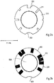
- FIGS. 2a and 2b show a top view of two exemplary embodiments of detector frames (code rings) coded according to the invention.
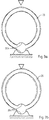
- Figures 3a and 3b show the top view of an embodiment of the clamping ring according to the invention in two positions.
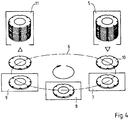
- FIG. 4 shows the diagram of an exemplary evaluation sequence of the solid-state dosimeters according to the invention in an automatic machine.
- FIGS 1, 1a and 1b show a dosimeter according to the invention in a stacked construction in cross section and corresponding exploded views.
- the dosimeter contains two detectors 10, namely an upper TLD thin-film detector 101 for determining the skin dose and a lower TLD tablet detector 102 for determining the depth dose. Instead of the tablet detector 102, however, a second thin-film detector 101 can also be used.
- the detectors are fixed by a clamping ring 20 and covered by a front, thin film 30 acting as a radiation filter and by a thick rear film 40.
- Tension ring 20 and foils 30, 40 together form a hermetically sealed dosimeter casing.
- the detectors 10, 101, 102 consist of a detector core 100 and a code ring which inextricably surrounds this as a detector frame 200.
- the detector core 100 has a diameter of 10 mm.
- the core 100 consists of a 1 mm thick substrate plate 110, e.g. made of aluminum, which is coated with a radiation-sensitive 0.1 - 0.2 mm thin layer 111, e.g. made of LiF: Mg, Ti is permanently welded by hot pressing.
- a radiation sensitive, self-supporting tablet 112 e.g. from LIF: Mg, Ti used.
- the radiation-sensitive cores are inserted as far as possible into the code ring 200 (inner diameter 10 mm, outer diameter 17 mm, 1.5 mm thick), e.g. made of Al, inserted and permanently connected to it by a press fit.
- FIGS. 2a and 2b show two preferred embodiments of the detector coding according to the invention, namely a decadal coding with continuous slots 211 and a binary coding with depressions 212 in a cover layer 220 on the detector frame 200.
- the first embodiment of the code ring according to the invention is provided with six slot decades, each offset by 45 °, for numerical identification, and a further two cutouts 202, 203 for positioning in the dosimeter casing and in the evaluation device.
- the number slots 211 are rectangular with a uniform width of 1 mm.
- the first decade (100) is 1:30 h
- the second decade (101) is 3:00 h
- the third decade (102) is 4:30 h
- the fourth decade (103) is 7:30 h
- the fifth decade (104) at 9:00 h
- the sixth decade (105) at 10:30 h.
- Up to 1 million dosimeters can be encoded.
- the number 287508 is encoded as a dosimeter number.
- the asymmetrical recess 202 at 12:00 h serves to differentiate between upper and lower detectors 10 and for detection accidental head positions.
- the circular recess 203 at 6:00 h serves to set the correct angular position through a temporarily inserted nose, especially when reading the code.
- Upper and lower detector 10 receive an identical slot coding as a dosimeter number, which can be read photoelectrically through the cover foils (30, 40) even when the dosimeter is closed.
- the code rings 200 do not have to be coded individually, but can instead be provided with slots 211 for the same numbers in groups.
- the invention is not limited to this example. Rather, other arrangements can also be made on the code ring 200, wherein the sequence of the recesses 210, their angular position and the width can be varied. The number of steps in the slots 211 changes accordingly if a system other than the decadal system is to be used.
- a binary, particularly advantageous, different type of coding with a corresponding design of the code ring 200 is shown by way of example in FIG. 2b.
- the inner diameter of the code ring 200 is 10 mm, the outer diameter 17 mm.
- a circular recess 203 (5 mm diameter, 4 mm segment width) serves for positioning and for transporting the detector 10 in the evaluation device.
- the recesses 210 on the code ring 200 here consist of depressions 212, namely of superficial, radial millings 1.5 mm wide and 0.3 mm deep. It is advantageous to apply a superficial cover layer 220, e.g. a flame-sprayed ceramic layer (Al2O3; 0.2 mm thick), which is removed in the area of the millings 212, so that different strips of ceramic (Al2O3) and metal (Al) form the code structure on the detector frame 200.
- a superficial cover layer 220 e.g. a flame-sprayed ceramic layer (Al2O3; 0.2 mm thick), which
- FIGS. 3a and 3b show a top view of an embodiment of a clamping ring 20 according to the invention.
- This is elastically deformable and elliptical, for example with a long inner axis of 18 mm and a short inner axis of 16.5 mm.
- Figure 3a shows a clamping ring 20 in the relaxed, elliptical state and Figure 3b in the tensioned, almost circularly deformed state.
- An arrow symbolizes the force acting on the clamping ring, which deforms it elastically.
- the detectors 10, for example with a diameter of 17 mm can be easily inserted by compressing the clamping ring 20. When unloaded, the clamping ring 20 adapts to the contours of the detectors 10 and fixes them. The detectors 10 are removed by compressing the clamping ring 20 again.
- An inner and an outer circular nose 204 serve to position the detectors 10 in the clamping ring 20 and the clamping ring 20 in the dosimeter holder.
- up to 200 1.5 mm thick detectors 10, corresponding to 100 solid-state dosimeters composed of two detectors 10, can be stacked in a cylindrical, compact magazine - 350 mm long, 25 mm in diameter - and can be automatically evaluated and regenerated in one continuous operation.
- the procedure is as follows: the dosimeters arriving at a central measuring point are opened one after the other by removing the cover foils 30, 40 and stacked one behind the other in a collecting device in a distinctive manner. A batch of dosimeters created in this way holds up to 100 dosimeters.
- the clamping rings 20 of all dosimeters are now opened simultaneously, and the detectors, which are now movable, are pushed en bloc into a tubular magazine by means of a stamp.
- FIG. 4 shows the evaluation process.
- the filled input magazine 5 is used in the machine.
- each individual detector 10 first reaches a code reader 7 for the purpose of registering the respective dosimeter number and the upper or lower position of the detector 10 in the dosimeter.
- the detector 10 is fed to the dose reader 9, consisting of a heating source and a photomultiplier.
- the skin and depth dose are calculated from the measured value using the correction and calibration factors stored in a computer and assigned to a specific person stored by name using the stored code data.
- the detector 10 can pass through an irradiation station 8 and again through the code reader 7 and the dose reader 9 to check its individual responsiveness.
- the detectors 10 then reach the output magazine 11.
- the detectors 10 return from the exit magazine 11 to the collecting device.
- the associated detectors 10 of a dosimeter are again provided with a clamping ring 20 and, after their removal from the collecting device, are covered with foils 30, 40.
- the marked, ready-to-measure dosimeter is returned to its user.
- the advantages of the invention result from the construction of a solid-state dosimeter with stacked individual detectors, which are unmistakably and permanently coded and which permit fast, reliable evaluation in an automatic machine and full regeneration at 400 ° C.
- the stacking arrangement allows small dimensions of the dosimeter (20 to 25 mm diameter, 3 mm thick) and the determination of the skin and depth dose in the case of stacked detectors.
- Both thin-film and tablet detectors without Teflon components can be used in a dosimeter according to the invention.
- more than two detectors and different radiation filters can also be arranged between the detectors in the stack, e.g. for the purpose of energy analysis of the radiation received.
- several dosimeters according to the invention with detectors for different radiations can be juxtaposed, e.g. in a common holder.
- the embodiment of the invention is not limited to the preferred exemplary embodiments specified above. Rather, a number of variants are conceivable which make use of the solution shown, even in the case of fundamentally different types.
Landscapes
- Physics & Mathematics (AREA)
- Health & Medical Sciences (AREA)
- Life Sciences & Earth Sciences (AREA)
- General Physics & Mathematics (AREA)
- High Energy & Nuclear Physics (AREA)
- Molecular Biology (AREA)
- Spectroscopy & Molecular Physics (AREA)
- Measurement Of Radiation (AREA)
Applications Claiming Priority (2)
| Application Number | Priority Date | Filing Date | Title |
|---|---|---|---|
| DE4105126 | 1991-02-15 | ||
| DE19914105126 DE4105126A1 (de) | 1991-02-15 | 1991-02-15 | Codiertes festkoerperdosimeter |
Publications (2)
| Publication Number | Publication Date |
|---|---|
| EP0499350A2 true EP0499350A2 (fr) | 1992-08-19 |
| EP0499350A3 EP0499350A3 (en) | 1995-02-22 |
Family
ID=6425383
Family Applications (1)
| Application Number | Title | Priority Date | Filing Date |
|---|---|---|---|
| EP92250028A Withdrawn EP0499350A3 (en) | 1991-02-15 | 1992-02-10 | Encoded solid state dosimeter |
Country Status (2)
| Country | Link |
|---|---|
| EP (1) | EP0499350A3 (fr) |
| DE (1) | DE4105126A1 (fr) |
Cited By (2)
| Publication number | Priority date | Publication date | Assignee | Title |
|---|---|---|---|---|
| US6707042B2 (en) * | 2000-09-14 | 2004-03-16 | Forschungszentrum Karlscruhe Gmbh | Apparatus for reading codes of thermoluminescence detectors |
| FR2971058A1 (fr) * | 2011-02-02 | 2012-08-03 | Commissariat Energie Atomique | Charge sensible pour dosimetrie passive, dosimetre comportant une telle charge sensible et systeme de lecture par illumination d'une telle charge sensible |
Families Citing this family (1)
| Publication number | Priority date | Publication date | Assignee | Title |
|---|---|---|---|---|
| CN105068105B (zh) * | 2015-08-18 | 2017-09-26 | 浙江建安检测研究院有限公司 | 加速器机头泄漏辐射测试方法 |
Family Cites Families (7)
| Publication number | Priority date | Publication date | Assignee | Title |
|---|---|---|---|---|
| US3567922A (en) * | 1965-02-15 | 1971-03-02 | Eg & G Inc | Thermoluminescent dosimeter and method |
| US3638017A (en) * | 1969-12-23 | 1972-01-25 | Atomic Energy Commission | Thermoluminescent dosimeter encoding and readout method |
| GB1480618A (en) * | 1973-12-05 | 1977-07-20 | Harshaw Chem Corp | Laminated dosimetric card |
| GB1471893A (en) * | 1974-11-20 | 1977-04-27 | Pitman Ltd D | Thermoluminescent dosimeter |
| DE2702836C2 (de) * | 1977-01-25 | 1983-12-22 | Frieseke & Hoepfner Gmbh, 8520 Erlangen | Personendosimeter |
| DE3100868C2 (de) * | 1981-01-14 | 1986-07-24 | Kernforschungsanlage Jülich GmbH, 5170 Jülich | Thermolumineszenzdosimeter zur Ermittlung der Dosis in Abhängigkeit von der Gewebetiefe |
| DE3226378A1 (de) * | 1982-07-12 | 1984-01-12 | Holzapfel, Georg, Dr., 1000 Berlin | Verfahren zur herstellung eines duennschicht-detektors fuer ein integrierendes festkoerperdosimeter |
-
1991
- 1991-02-15 DE DE19914105126 patent/DE4105126A1/de not_active Withdrawn
-
1992
- 1992-02-10 EP EP92250028A patent/EP0499350A3/de not_active Withdrawn
Cited By (5)
| Publication number | Priority date | Publication date | Assignee | Title |
|---|---|---|---|---|
| US6707042B2 (en) * | 2000-09-14 | 2004-03-16 | Forschungszentrum Karlscruhe Gmbh | Apparatus for reading codes of thermoluminescence detectors |
| EP1189075A3 (fr) * | 2000-09-14 | 2006-08-09 | GSF-Forschungszentrum für Umwelt und Gesundheit GmbH | Dispositif de lecture de code pour un détecteur à thermoluminescence |
| FR2971058A1 (fr) * | 2011-02-02 | 2012-08-03 | Commissariat Energie Atomique | Charge sensible pour dosimetrie passive, dosimetre comportant une telle charge sensible et systeme de lecture par illumination d'une telle charge sensible |
| WO2012104533A3 (fr) * | 2011-02-02 | 2012-11-22 | Commissariat A L'energie Atomique Et Aux Energies Alternatives | Charge sensible pour dosimetrie passive, dosimetre comportant une telle charge sensible et systeme de lecture par illumination d'une telle charge sensible |
| US9081101B2 (en) | 2011-02-02 | 2015-07-14 | Commissariat A L'energie Atomique Et Aux Energies Alternatives | Sensitive charge for passive dosimetry, dosimeter comprising such a sensitive charge and system for reading by illumination for such a sensitive charge |
Also Published As
| Publication number | Publication date |
|---|---|
| DE4105126A1 (de) | 1992-08-20 |
| EP0499350A3 (en) | 1995-02-22 |
Similar Documents
| Publication | Publication Date | Title |
|---|---|---|
| EP0842491B1 (fr) | Support de donnees comportant un module pourvu d'un composant et d'une bobine, et procede de fabrication dudit support de donnees | |
| EP0099852B1 (fr) | Détecteur à couche mince pour un dosimètre intégral et son procédé de fabrication | |
| DE3300849A1 (de) | Vorrichtung zum ermitteln der einfallsrichtung von optischer strahlung | |
| EP0032368A1 (fr) | Carte de données | |
| DE10256979A1 (de) | CsI-Scintillatordirektbeschichtung für eine verbesserte Lebensdauer einer digitalen Röntgenstrahldetektorbaugruppe | |
| DE1950070B2 (de) | Verfahren zum kodieren von diodenanordnungen | |
| EP0499350A2 (fr) | Dosimètre solide codé | |
| DE7935267U1 (de) | Identifizierungskarte | |
| DE3855197T2 (de) | Verfahren zum Plazieren einer elektronischen Komponente und seiner elektronsichen Verbindungen auf einer Unterlage | |
| DE2452900A1 (de) | Dosimetrische karte | |
| DE1062967B (de) | Anordnung zur Abfuehlung von Aufzeichnungstraegern mittels lichtelektrischer Speicherzellen | |
| EP3520156A1 (fr) | Unité d'accumulation d'énergie électrique à tôle de déflexion structurée et procédé pour structurer une tôle de déflexion d'une unité d'accumulation d'énergie électrique | |
| DE19541647C2 (de) | Verfahren und Vorrichtung zur Identifizierung von Munition | |
| US3725659A (en) | Thermoluminescence dosimeter system | |
| DE4138519A1 (de) | Thermolumineszierendes hochtemperatur-dosimeter sowie verfahren zur herstellung und verwendung desselben | |
| DE3035933A1 (de) | Pyroelektrischer detektor sowie verfahren zur herstellung eines solchen detektors | |
| DE2039781A1 (de) | Mehrkanalige Magnetkopfeinheit und Verfahren zu ihrer Herstellung | |
| DE2215798A1 (de) | Magnetruehrgeraet | |
| DE69931575T2 (de) | Testanordnung für elektronische Speicherkarten | |
| EP1023614B1 (fr) | Dosimetre pour la detection de rayonnements utilisant la radio-photo-luminescence | |
| EP0216136B1 (fr) | Arrangement d'éléments sensibles dans un cadre de maintien pour un détecteur pyroélectrique et son procédé de fabrication | |
| DE1903562C (de) | Festkörper Bildwandler | |
| CH203790A (de) | Für Röntgen- und andere kurzwellige Strahlen empfindliche Sperrschichtphotozelle. | |
| DE2805661A1 (de) | Verfahren zur bestimmung einer strahlungsdosis mittels eines dosimeters mit thermisch stimulierter leitfaehigkeit | |
| EP0760522A2 (fr) | Résistance ajustable |
Legal Events
| Date | Code | Title | Description |
|---|---|---|---|
| PUAI | Public reference made under article 153(3) epc to a published international application that has entered the european phase |
Free format text: ORIGINAL CODE: 0009012 |
|
| AK | Designated contracting states |
Kind code of ref document: A2 Designated state(s): AT DE FR GB IT |
|
| PUAL | Search report despatched |
Free format text: ORIGINAL CODE: 0009013 |
|
| RHK1 | Main classification (correction) |
Ipc: G01T 1/11 |
|
| AK | Designated contracting states |
Kind code of ref document: A3 Designated state(s): AT DE FR GB IT |
|
| 18W | Application withdrawn |
Withdrawal date: 19950418 |