EP0499361A1 - Fixations de bandes décoratives - Google Patents
Fixations de bandes décoratives Download PDFInfo
- Publication number
- EP0499361A1 EP0499361A1 EP92300462A EP92300462A EP0499361A1 EP 0499361 A1 EP0499361 A1 EP 0499361A1 EP 92300462 A EP92300462 A EP 92300462A EP 92300462 A EP92300462 A EP 92300462A EP 0499361 A1 EP0499361 A1 EP 0499361A1
- Authority
- EP
- European Patent Office
- Prior art keywords
- panel
- trim panel
- trim
- detent members
- clips
- Prior art date
- Legal status (The legal status is an assumption and is not a legal conclusion. Google has not performed a legal analysis and makes no representation as to the accuracy of the status listed.)
- Withdrawn
Links
Images

Classifications
-
- F—MECHANICAL ENGINEERING; LIGHTING; HEATING; WEAPONS; BLASTING
- F16—ENGINEERING ELEMENTS AND UNITS; GENERAL MEASURES FOR PRODUCING AND MAINTAINING EFFECTIVE FUNCTIONING OF MACHINES OR INSTALLATIONS; THERMAL INSULATION IN GENERAL
- F16B—DEVICES FOR FASTENING OR SECURING CONSTRUCTIONAL ELEMENTS OR MACHINE PARTS TOGETHER, e.g. NAILS, BOLTS, CIRCLIPS, CLAMPS, CLIPS OR WEDGES; JOINTS OR JOINTING
- F16B5/00—Joining sheets or plates, e.g. panels, to one another or to strips or bars parallel to them
- F16B5/12—Fastening strips or bars to sheets or plates, e.g. rubber strips, decorative strips for motor vehicles, by means of clips
- F16B5/123—Auxiliary fasteners specially designed for this purpose
- F16B5/125—Auxiliary fasteners specially designed for this purpose one of the auxiliary fasteners is comprising wire or sheet material or is made thereof
-
- B—PERFORMING OPERATIONS; TRANSPORTING
- B60—VEHICLES IN GENERAL
- B60R—VEHICLES, VEHICLE FITTINGS, OR VEHICLE PARTS, NOT OTHERWISE PROVIDED FOR
- B60R13/00—Elements for body-finishing, identifying, or decorating; Arrangements or adaptations for advertising purposes
- B60R13/02—Internal Trim mouldings ; Internal Ledges; Wall liners for passenger compartments; Roof liners
- B60R13/0206—Arrangements of fasteners and clips specially adapted for attaching inner vehicle liners or mouldings
-
- F—MECHANICAL ENGINEERING; LIGHTING; HEATING; WEAPONS; BLASTING
- F16—ENGINEERING ELEMENTS AND UNITS; GENERAL MEASURES FOR PRODUCING AND MAINTAINING EFFECTIVE FUNCTIONING OF MACHINES OR INSTALLATIONS; THERMAL INSULATION IN GENERAL
- F16B—DEVICES FOR FASTENING OR SECURING CONSTRUCTIONAL ELEMENTS OR MACHINE PARTS TOGETHER, e.g. NAILS, BOLTS, CIRCLIPS, CLAMPS, CLIPS OR WEDGES; JOINTS OR JOINTING
- F16B5/00—Joining sheets or plates, e.g. panels, to one another or to strips or bars parallel to them
- F16B5/12—Fastening strips or bars to sheets or plates, e.g. rubber strips, decorative strips for motor vehicles, by means of clips
- F16B5/123—Auxiliary fasteners specially designed for this purpose
-
- Y—GENERAL TAGGING OF NEW TECHNOLOGICAL DEVELOPMENTS; GENERAL TAGGING OF CROSS-SECTIONAL TECHNOLOGIES SPANNING OVER SEVERAL SECTIONS OF THE IPC; TECHNICAL SUBJECTS COVERED BY FORMER USPC CROSS-REFERENCE ART COLLECTIONS [XRACs] AND DIGESTS
- Y10—TECHNICAL SUBJECTS COVERED BY FORMER USPC
- Y10T—TECHNICAL SUBJECTS COVERED BY FORMER US CLASSIFICATION
- Y10T24/00—Buckles, buttons, clasps, etc.
- Y10T24/30—Trim molding fastener
-
- Y—GENERAL TAGGING OF NEW TECHNOLOGICAL DEVELOPMENTS; GENERAL TAGGING OF CROSS-SECTIONAL TECHNOLOGIES SPANNING OVER SEVERAL SECTIONS OF THE IPC; TECHNICAL SUBJECTS COVERED BY FORMER USPC CROSS-REFERENCE ART COLLECTIONS [XRACs] AND DIGESTS
- Y10—TECHNICAL SUBJECTS COVERED BY FORMER USPC
- Y10T—TECHNICAL SUBJECTS COVERED BY FORMER US CLASSIFICATION
- Y10T24/00—Buckles, buttons, clasps, etc.
- Y10T24/30—Trim molding fastener
- Y10T24/304—Resilient metal type
- Y10T24/308—Wire formed
-
- Y—GENERAL TAGGING OF NEW TECHNOLOGICAL DEVELOPMENTS; GENERAL TAGGING OF CROSS-SECTIONAL TECHNOLOGIES SPANNING OVER SEVERAL SECTIONS OF THE IPC; TECHNICAL SUBJECTS COVERED BY FORMER USPC CROSS-REFERENCE ART COLLECTIONS [XRACs] AND DIGESTS
- Y10—TECHNICAL SUBJECTS COVERED BY FORMER USPC
- Y10T—TECHNICAL SUBJECTS COVERED BY FORMER US CLASSIFICATION
- Y10T24/00—Buckles, buttons, clasps, etc.
- Y10T24/44—Clasp, clip, support-clamp, or required component thereof
- Y10T24/44017—Clasp, clip, support-clamp, or required component thereof with specific mounting means for attaching to rigid or semirigid supporting structure or structure-to-be-secured
- Y10T24/44026—Clasp, clip, support-clamp, or required component thereof with specific mounting means for attaching to rigid or semirigid supporting structure or structure-to-be-secured for cooperating with aperture in supporting structure or structure-to-be-secured
Definitions
- the present invention relates to trim fastenings and in particular to fastenings for trim panels for vehicles, for example, the door trim panels of motor vehicles.
- the trim panels are moulded and may wrap around the edges of the door panel. As a result, there may be no suitable position to locate press fastenings of the type used hitherto and, furthermore, it may not be possible to insert an implement between the trim and door panel to remove the trim panel.
- the present invention provides a fastening suitable for use with moulded trim panels.
- a fastening for securing a trim panel to a support panel is characterised in that an elongate element defines a plurality of transverse detent members spaced along its length, the elongate element being secured to the trim panel with the detent members spaced from the trim panel on the inside thereof.
- a plurality of clips being provided on the support panel, each clip corresponding to one of the detent members, the clips defining a surface for engagement by the detent member, said surface diverging away from the support panel, so that movement of the trim panel longitudinally of the elongate member will cause each detent member to move along said surface of an associated clip, the detent members and trim panel being drawn towards the support panel.
- the elongate element is formed from wire which is bent to form detent members, the detent members being interconnected by longitudinally extending lengths of wire.
- the longitudinally extending lengths of wire are secured to the trim panel in suitable manner, for example by the use of a bonding material and/or tape.
- the clips may be formed integrally of the support panel or separate clips made of metal or plastics material may be secured to the support panel in suitable manner.
- FIG 1 illustrates a moulded door trim panel 10 for a motor vehicle.
- the trim panel 10 has a central recessed portion 11, providing access to a storage pocket 12 formed along the lower edge.
- the side and lower edges of the door have a peripheral shoulder formation 13 adapted to locate against a corresponding formation 14 on the door panel 15 (see Figure 4), the edge 16 of the trim panel 10 extending over the edge of the door panel 15.
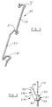
- Elongate elements 20, as illustrated in Figure 2 are formed from wire bent to provide a plurality of detent members 21 interconnected by lengths of wire 22.
- the elongate elements 20 are secured to the inside of trim panel 10, the lengths 22 being bonded to the panel 10 by means of an adhesive compound 23 and/or tape 24.
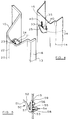
- Clips 25 are formed from sheet material bent to provide a clip formation 26 and a retaining formation 27.
- the clip formation 26 is of channel section having a pair of side walls 30 interconnected, remote from the retaining formation 27, by web 31.
- the retaining formation 27 is formed by bending the edges of walls 30 remote from web 31, outwardly to provide co-planer shoulder portions 32.
- the ends of the walls 30 are then bent back to provide substantially parallel leg formations 33 which extend from the shoulder formations 32 on the side thereof opposite to the clip formation 26.
- the ends of the leg formations 33 are bent back to form retaining lugs 34.
- the edges 35 of walls 30 are inclined to provide an abutment face which diverges away from the plane of the shoulder portions 32.
- leg formations 33 of clips 25 engage through slots 40 in the door panel 15, so that the shoulder formations 32 will engage the door panel 15 and the retaining lugs 34 will engage the opposite face of the door panel 15 to retain the clip 25 in position.
- a plurality of clips 25 are secured to the door panel 15 in this manner.
- the clips 25 are located on the door panel 15 to correspond to the location of the detent members 21 on the trim panel 10.
- the trim panel 10 may thus be positioned with respect to the door panel 15, so that each abutment member 25 engages over the clip formation 26 of one of the clips 25.
- the trim panel 10 may then be moved relative to the door panel 15, so that the detent members 21 move along the inclined edges 35 of the clips 25.
- the trim panel 10 is thus drawn towards the door panel 15 until the shoulder formation 13 on the trim panel 10 engages the corresponding formation 14 on the door panel 15. This relative movement of the trim panel 10 and door panel 15 will also cause the edge 16 of trim panel 10 to locate around the edge of the door panel 15.
- the clip 50 is moulded from a plastics material.
- the clip 50 has a clip formation 51 with inclined abutment face 52 and a base portion 53.
- the base portion is adapted to locate against the door panel, a retaining formation 54 extending through an aperture 58 in the door panel 15, the retaining formation 54 having formations 55 which will engage the door panel on the side thereof remote from the base portion 53.
- a spigot formation 56 is also provided on the base portion 53 to locate in a second aperture 59 in the door panel 15 to prevent rotation of the clip 50 with respect to the door panel 15.
- a resilient leaf formation extends from the free end of the base portion 53 towards the junction between the base portion 53 and clip formation 51.
- the plastic clips 50 will act in similar manner to the metal clips 25 described above, the detent members 21 engaging and moving along the face 52 of clip formation 51.
- the resilient leaf formation 57 will apply a load to the detent members 21 to retain the detent member in position while the trim panel 10 is fitted but permitting release of the detent member 21 for removal of the trim panel 10.
- the elongate elements are formed from wire, elements of other constructions may be used.
- the elongate element may be of ladder configuration having a pair of parallel longitudinal members which are secured to the trim panel, the detent members extending between the longitudinal members, out of the plane thereof.
- the clips may be formed integrally of the support panel by, for example, pressing tabs out of the support panel, so that the tabs diverge away from the plane of the support panel.
Landscapes
- Engineering & Computer Science (AREA)
- General Engineering & Computer Science (AREA)
- Mechanical Engineering (AREA)
- Vehicle Interior And Exterior Ornaments, Soundproofing, And Insulation (AREA)
- Connection Of Plates (AREA)
Applications Claiming Priority (2)
| Application Number | Priority Date | Filing Date | Title |
|---|---|---|---|
| GB919102869A GB9102869D0 (en) | 1991-02-12 | 1991-02-12 | Trim fastenings |
| GB9102869 | 1991-02-12 |
Publications (1)
| Publication Number | Publication Date |
|---|---|
| EP0499361A1 true EP0499361A1 (fr) | 1992-08-19 |
Family
ID=10689849
Family Applications (1)
| Application Number | Title | Priority Date | Filing Date |
|---|---|---|---|
| EP92300462A Withdrawn EP0499361A1 (fr) | 1991-02-12 | 1992-01-20 | Fixations de bandes décoratives |
Country Status (4)
| Country | Link |
|---|---|
| US (1) | US5197167A (fr) |
| EP (1) | EP0499361A1 (fr) |
| JP (1) | JPH04310423A (fr) |
| GB (1) | GB9102869D0 (fr) |
Cited By (1)
| Publication number | Priority date | Publication date | Assignee | Title |
|---|---|---|---|---|
| US6858189B1 (en) | 1999-02-17 | 2005-02-22 | Protensive Limited (A Company Incorporated In England) | Rotating surface of revolution reactor with feed and collection mechanisms |
Families Citing this family (4)
| Publication number | Priority date | Publication date | Assignee | Title |
|---|---|---|---|---|
| CA2282644A1 (fr) * | 1997-02-27 | 1998-09-03 | John Cennamo | Attache a ressort pour fixer un composant electronique a un puit thermique et assemblage utilisant cette attache |
| US20080315620A1 (en) * | 2007-06-25 | 2008-12-25 | Faurecua Interior Systems U.S.A., Inc. | Auto Panel Attachment Device |
| US11118791B2 (en) * | 2017-03-03 | 2021-09-14 | Mitsubishi Electric Corporation | Indoor unit of air-conditioning apparatus |
| KR102729134B1 (ko) * | 2020-02-28 | 2024-11-13 | 닛폰세이테츠 가부시키가이샤 | 패널 부품의 보강 구조 |
Citations (3)
| Publication number | Priority date | Publication date | Assignee | Title |
|---|---|---|---|---|
| DE182173C (fr) * | ||||
| US3916055A (en) * | 1971-05-20 | 1975-10-28 | Illinois Tool Works | Adhesive attachment system for decorative trim strips |
| DE3203705A1 (de) * | 1981-02-05 | 1982-10-07 | La Télémécanique Electrique, 92002 Nanterre, Hauts-de-Seine | Vorrichtung zur befestigung von geraeten, insbesondere elektrogeraeten |
Family Cites Families (10)
| Publication number | Priority date | Publication date | Assignee | Title |
|---|---|---|---|---|
| US2137883A (en) * | 1936-08-15 | 1938-11-22 | Briggs Mfg Co | Trim panel and fastener |
| US2137653A (en) * | 1936-08-27 | 1938-11-22 | Briggs Mfg Co | Fastener device |
| US2287606A (en) * | 1940-07-08 | 1942-06-23 | Chrysler Corp | Fastening device |
| US2659951A (en) * | 1948-03-17 | 1953-11-24 | Tinnerman Products Inc | Sheet metal snap fastener |
| US2938249A (en) * | 1956-11-05 | 1960-05-31 | Gen Motors Corp | Weather strip assembly |
| US3331171A (en) * | 1964-06-09 | 1967-07-18 | Edward C Hallock | Joint covers |
| US3251105A (en) * | 1964-12-11 | 1966-05-17 | Penna Rose M La | Pop molding clip |
| DE2211363A1 (de) * | 1972-03-09 | 1973-09-13 | Daimler Benz Ag | Scheuerleiste fuer kraftfahrzeuge, insbesondere fuer personenkraftwagen |
| JPS6144341U (ja) * | 1984-08-28 | 1986-03-24 | 豊田合成株式会社 | ア−チ形状サイドモ−ル |
| JPS60191851A (ja) * | 1984-11-02 | 1985-09-30 | Toyoda Gosei Co Ltd | プロテクタモ−ルの取付方法 |
-
1991
- 1991-02-12 GB GB919102869A patent/GB9102869D0/en active Pending
-
1992
- 1992-01-20 EP EP92300462A patent/EP0499361A1/fr not_active Withdrawn
- 1992-01-31 US US07/830,116 patent/US5197167A/en not_active Expired - Fee Related
- 1992-02-12 JP JP4024923A patent/JPH04310423A/ja active Pending
Patent Citations (3)
| Publication number | Priority date | Publication date | Assignee | Title |
|---|---|---|---|---|
| DE182173C (fr) * | ||||
| US3916055A (en) * | 1971-05-20 | 1975-10-28 | Illinois Tool Works | Adhesive attachment system for decorative trim strips |
| DE3203705A1 (de) * | 1981-02-05 | 1982-10-07 | La Télémécanique Electrique, 92002 Nanterre, Hauts-de-Seine | Vorrichtung zur befestigung von geraeten, insbesondere elektrogeraeten |
Cited By (4)
| Publication number | Priority date | Publication date | Assignee | Title |
|---|---|---|---|---|
| US6858189B1 (en) | 1999-02-17 | 2005-02-22 | Protensive Limited (A Company Incorporated In England) | Rotating surface of revolution reactor with feed and collection mechanisms |
| US6977063B1 (en) | 1999-02-17 | 2005-12-20 | Protensive Limited | Rotating surface of revolution reactor with shearing mechanisms |
| US7115235B1 (en) | 1999-02-17 | 2006-10-03 | Protensive Limited | Rotating surface of revolution reactor with temperature control mechanisms |
| US7247202B1 (en) | 1999-02-17 | 2007-07-24 | Protensive Limited | Process for the conversion of a fluid phase substrate by dynamic heterogeneous contact with a solid agent |
Also Published As
| Publication number | Publication date |
|---|---|
| GB9102869D0 (en) | 1991-03-27 |
| JPH04310423A (ja) | 1992-11-02 |
| US5197167A (en) | 1993-03-30 |
Similar Documents
| Publication | Publication Date | Title |
|---|---|---|
| US5135188A (en) | Attachable bundling strap | |
| CA2412228C (fr) | Procedes permettant de fixer un habillage a un vehicule | |
| US5561003A (en) | Molding | |
| GB2184771A (en) | Resilient clip | |
| US4527759A (en) | Unitary clip for retaining control lines on a flange | |
| GB2219338A (en) | Windscreen mouldings | |
| CA2172691A1 (fr) | Agrafe de cablage | |
| GB2264325A (en) | Vehicle windscreen mounting clips | |
| US5197167A (en) | Trim fastenings | |
| US4978091A (en) | Bundling strap | |
| US5058843A (en) | Adjustable trim strip mounting assembly | |
| US4179859A (en) | Molding retaining clip | |
| CA2424054C (fr) | Attache servant a fixer un habillage de coin ou enveloppant sur un vehicule | |
| HU206229B (en) | Window having frame provided with notch for internal panel elements | |
| US20020164200A1 (en) | Vehicle interior fastener clip assembly for securing a rubber molding between a vehicle dashboard and windshield | |
| EP0047864B1 (fr) | Dispositif de fixation pour éléments allongés tels que des câbles | |
| EP0814229A1 (fr) | Arrangement et système de fixation d'un profil flexible | |
| US4486985A (en) | Molding clip | |
| JPH0216919Y2 (fr) | ||
| US4143906A (en) | Molding clip | |
| US4180957A (en) | Molding clip | |
| US2748840A (en) | Sheet material clip | |
| EP0323014A2 (fr) | Système de positionnement d'une fenêtre | |
| JPS6040888Y2 (ja) | フアスナ装置 | |
| JPH07246889A (ja) | ルーフモールの取付構造 |
Legal Events
| Date | Code | Title | Description |
|---|---|---|---|
| PUAI | Public reference made under article 153(3) epc to a published international application that has entered the european phase |
Free format text: ORIGINAL CODE: 0009012 |
|
| AK | Designated contracting states |
Kind code of ref document: A1 Designated state(s): DE FR GB IT SE |
|
| 17P | Request for examination filed |
Effective date: 19930115 |
|
| 17Q | First examination report despatched |
Effective date: 19930917 |
|
| 18D | Application deemed to be withdrawn |
Effective date: 19940329 |