EP0499445B1 - Système de chromatographie à gaz pour l'analyse des gaz industriels - Google Patents
Système de chromatographie à gaz pour l'analyse des gaz industriels Download PDFInfo
- Publication number
- EP0499445B1 EP0499445B1 EP92301130A EP92301130A EP0499445B1 EP 0499445 B1 EP0499445 B1 EP 0499445B1 EP 92301130 A EP92301130 A EP 92301130A EP 92301130 A EP92301130 A EP 92301130A EP 0499445 B1 EP0499445 B1 EP 0499445B1
- Authority
- EP
- European Patent Office
- Prior art keywords
- sample
- gas
- analyzer
- unit
- manifold
- Prior art date
- Legal status (The legal status is an assumption and is not a legal conclusion. Google has not performed a legal analysis and makes no representation as to the accuracy of the status listed.)
- Expired - Lifetime
Links
Images




Classifications
-
- G—PHYSICS
- G01—MEASURING; TESTING
- G01N—INVESTIGATING OR ANALYSING MATERIALS BY DETERMINING THEIR CHEMICAL OR PHYSICAL PROPERTIES
- G01N30/00—Investigating or analysing materials by separation into components using adsorption, absorption or similar phenomena or using ion-exchange, e.g. chromatography or field flow fractionation
- G01N30/02—Column chromatography
- G01N30/88—Integrated analysis systems specially adapted therefor, not covered by a single one of the groups G01N30/04 - G01N30/86
-
- G—PHYSICS
- G01—MEASURING; TESTING
- G01N—INVESTIGATING OR ANALYSING MATERIALS BY DETERMINING THEIR CHEMICAL OR PHYSICAL PROPERTIES
- G01N30/00—Investigating or analysing materials by separation into components using adsorption, absorption or similar phenomena or using ion-exchange, e.g. chromatography or field flow fractionation
-
- G—PHYSICS
- G01—MEASURING; TESTING
- G01N—INVESTIGATING OR ANALYSING MATERIALS BY DETERMINING THEIR CHEMICAL OR PHYSICAL PROPERTIES
- G01N1/00—Sampling; Preparing specimens for investigation
- G01N1/02—Devices for withdrawing samples
- G01N1/22—Devices for withdrawing samples in the gaseous state
-
- G—PHYSICS
- G01—MEASURING; TESTING
- G01N—INVESTIGATING OR ANALYSING MATERIALS BY DETERMINING THEIR CHEMICAL OR PHYSICAL PROPERTIES
- G01N30/00—Investigating or analysing materials by separation into components using adsorption, absorption or similar phenomena or using ion-exchange, e.g. chromatography or field flow fractionation
- G01N30/02—Column chromatography
- G01N30/26—Conditioning of the fluid carrier; Flow patterns
- G01N30/28—Control of physical parameters of the fluid carrier
- G01N30/30—Control of physical parameters of the fluid carrier of temperature
- G01N2030/3084—Control of physical parameters of the fluid carrier of temperature ovens
-
- G—PHYSICS
- G01—MEASURING; TESTING
- G01N—INVESTIGATING OR ANALYSING MATERIALS BY DETERMINING THEIR CHEMICAL OR PHYSICAL PROPERTIES
- G01N30/00—Investigating or analysing materials by separation into components using adsorption, absorption or similar phenomena or using ion-exchange, e.g. chromatography or field flow fractionation
- G01N30/02—Column chromatography
- G01N30/88—Integrated analysis systems specially adapted therefor, not covered by a single one of the groups G01N30/04 - G01N30/86
- G01N2030/8881—Modular construction, specially adapted therefor
-
- G—PHYSICS
- G01—MEASURING; TESTING
- G01N—INVESTIGATING OR ANALYSING MATERIALS BY DETERMINING THEIR CHEMICAL OR PHYSICAL PROPERTIES
- G01N30/00—Investigating or analysing materials by separation into components using adsorption, absorption or similar phenomena or using ion-exchange, e.g. chromatography or field flow fractionation
- G01N30/02—Column chromatography
- G01N30/88—Integrated analysis systems specially adapted therefor, not covered by a single one of the groups G01N30/04 - G01N30/86
- G01N2030/8886—Analysis of industrial production processes
-
- G—PHYSICS
- G01—MEASURING; TESTING
- G01N—INVESTIGATING OR ANALYSING MATERIALS BY DETERMINING THEIR CHEMICAL OR PHYSICAL PROPERTIES
- G01N30/00—Investigating or analysing materials by separation into components using adsorption, absorption or similar phenomena or using ion-exchange, e.g. chromatography or field flow fractionation
- G01N30/02—Column chromatography
- G01N30/26—Conditioning of the fluid carrier; Flow patterns
- G01N30/28—Control of physical parameters of the fluid carrier
- G01N30/30—Control of physical parameters of the fluid carrier of temperature
Definitions
- the present invention relates to a process gas chromatographic system for analyzing a gas of interest by utilizing the difference in absorption between the gas and a filler filled in a column as a stationary phase.
- a process gas chromatographic system for analyzing components of process gases is employed to provide a sample gas extracted from a process line with an optimal condition required for analysis by means of a sample conditioner unit, supply this sample gas to an analyzer unit to separate the same into respective gas components for detection, and monitor process steps and perform various control operations based on the analysis results.
- US-A-3276 243 discloses a gas detection system which is held to an essentially constant overall temperature situation, wherein part of the system is explosion - proofed and the remainder is made readily accessible without disturbing the explosion proofing.
- CH-A-430278 discloses a compact chromatography system incorporating means for introducing the mixture to be analyzed, means for calibrating the sample to be analyzed, one or more chromatographic columns in which separation of the constituents of the sample occurs and a detector for detecting a foreign body in carrier fluid, and also incorporating a block made of appropriate material, particularly metal, provided with bored out hollows which in part form the means of introducing the mixture, means of calibration, means of introducing the carrier fluid, the detector and means for putting into operation at least one column.
- Fig. 9 shows a conventional gas chromatographic system.
- Reference numerals 1A and 1B denote process lines; 2, a sample conditioner unit; and 3, an analyzer unit.
- the process lines 1A and 1B, the sample conditioner unit 2, and the analyzer unit 3 constitute the gas chromatographic system.
- the sample conditioner unit 2 includes a vaporizer (not shown) for perfectly vaporizing heavy components of a sample gas SG to prevent its condensation, a filter (not shown) for removing dust from the sample gas SG, a rotor meter (not shown) for measuring the flow rates of the sample gas SG and a reference gas HG, needle valves (not shown) for adjusting the flow rates of the reference gas HG and the sample gas SG, and a selector switch (not shown) for selecting an appropriate flow path.
- These components in the sample conditioner unit 2 are built in a housing 4 and are connected to each other through piping.
- the analyzer unit 3 includes first and second series-connected columns 5 and 6, a sample valve 7, a back-flush valve 8, a detector 9, a pressure reducing valve (not shown), an electric unit 10, a constant temperature oven 11, and a heater 12.
- the constant temperature oven 11 accommodates the first and second columns 5 and 6, the sample valve 7, the back-flush valve 8, the detector 9, and the like such that they are kept at an optimal temperature for separation analysis of the sample gas SG by circulating air heated by the heater 12.
- the first column 5 consists of a packed column which has an inner diameter of about 1 mm to 4 mm and a length of about 0.5 m to 3 m and in which a stationary phase is filled.
- the first column 5 can efficiently separate low-boiling point components containing small amounts of carbon (C) at high speed.
- the second column 6 consists of a capillary column which has an inner diameter of about 0.1 mm to 4 mm and a length of about 0.5 m to 3 m and which has the inner wall surface coated with a liquid phase.
- the second column 6 cannot easily separate low-boiling point components containing small amounts of carbon but can efficiently separate high-boiling point components having large amounts of carbon at high speed.
- the temperature distribution in the constant temperature oven 11 cannot be made perfectly uniform due to the number of spray ports of the sample gas SG and a carrier gas CG and the layout of components of the system.
- variations in temperature also occur.
- the components such as the columns 5 and 6 cannot be maintained under optimal temperature conditions, whereby the detected concentrations of components do not often coincide with the sample concentrations, which results in difficulties in achieving accurate measurements.
- the sample valve 7 and the back-flush valve 8 are preferably maintained at high temperatures, and the second column 6 is preferably free from variations in temperature so as to improve the separation performance.
- a sample inlet portion between the sample conditioner unit 2 and the analyzer unit 3 is connected by a sample pipe 13.
- the electric unit 10 including an amplifier and a temperature controller, since located generally above the thermostat 11 together with the heater 12, is adversely affected by heat from the constant temperature oven 11 and the heater 12, thus degrading reliability of the apparatus. Further, the structure, in which the sample valve 7, the first and second columns 5 and 6, the detector 9, and the like are connected to each other through piping and couplings inside the constant temperature oven 11, may cause problems such as a difficult maintenance operation of these components.
- a gas chromatographic system for analyzing gas components comprising an analyzer unit including a sample valve having a detector and a heater built therein, and first and second columns wound around the periphery of the sample valve, a constant temperature oven in which the analyzer unit is accommodated, an analyzer case for accommodating the constant temperature oven, indicator means protruded from the analyzer case for displaying analysis processes and results, integrated sample conditioner means for providing an optimal condition for analysis, and coupler means for coupling the analyzer unit with the sample conditioner means so as to supply a sample gas and one of a carrier gas and a reference gas from the sample conditioner means to the analyzer unit.
- a gas chromatographic system 20 comprises a sample conditioner unit 2, an analyzer unit 3 arranged above the sample conditioner unit 2, and an electric unit 21 connected to the front surface of the analyzer unit 3.
- the gas chromatographic system 20 is fixed on a stanchion 22 through a bracket 24 by a plurality of bolts 23.
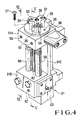
- the structure of the sample conditioner unit 2 will be described in detail with reference to Figs. 3 to 6.
- the sample conditioner unit 2 comprises a box-like housing 30 having an upper central open portion.
- a housing block 31 made of a metal such as stainless steel is accommodated in the box-like housing 30.
- the housing block 31 comprises vertically opposed, substantially horizontal upper and lower blocks 31A and 31B and a substantially vertical connecting portion 31C for connecting the upper and lower blocks 31A and 31B.
- a small block 36 having a carrier gas outlet port 32, a sample/reference gas outlet port 33, a sample gas inlet port 34, and a plurality of screw holes 35 is fixed on the upper surface of the upper block 31A by set screws 27.
- the small block 36 is covered with a cover 25 (Fig. 1).
- Two needle valve adjusting holes 37a and 37b are formed in the front surface of the upper block 31A.
- a carrier gas supply port 38 is formed in the left side surface of the upper block 31A.
- a bypass vent port 39 and a sample vent port 40 are formed in the right side surface of the upper block 31A.
- reference numeral 28 denotes a bolt mounting hole for receiving from below a bolt 65 for fixing a manifold 72 (to be described later).
- Reference numerals 29 denote positioning pins for positioning the manifold 72.
- Needle valves 50 and 51 are arranged midway along the sample/reference gas flow path 44 and the bypass vent flow path 45, respectively.
- the needle valves 50 and 51 are inserted into the needle valve adjusting holes 37a and 37b, respectively, and can be externally adjusted.
- a carrier gas CG is supplied to the carrier gas supply port 38 and is sent to the analyzer unit 3 through the carrier gas flow path 41 and the carrier gas outlet port 32.
- a sample gas SG after separated and analyzed by the analyzer unit 3 is supplied to the sample gas inlet port 34 and is discharged from the sample vent port 40 through the sample vent flow path 46.
- Two filter mounting holes 54a and 54b for respectively mounting filters 52 and 53, and a vaporizer mounting hole 56 for mounting a vaporizer 55 are formed in the front surface of the lower block 31B.
- the sample gas supply port 42, the reference gas supply port 43, a steam inlet 57, and a steam outlet 58 are formed in the lower surface of the lower block 31B.
- the selector switch 47 is incorporated inside the lower block 31B.
- the needle valve 50, the filters 52 and 53, the vaporizer 55, the selector switch 47, and a second rotor meter 60 are incorporated midway along the sample/reference gas flow path 44.
- a first rotor meter 59 is incorporated in the bypass vent flow path 45.
- the vaporizer 55 is arranged in a flow path between the sample gas supply port 42 and the filter 52.
- a reference gas HG is supplied to the reference gas supply port 43.
- Each of the first and second rotor meters 59 and 60 comprises a tapered pipe and a float.
- the first rotor meter 59 measures the bypass flow rate of the sample gas SG
- the second rotor meter 60 measures the flow rate of the gas supplied to the analyzer unit 3.
- the first and second rotor meters 59 and 60 are arranged between the upper and lower blocks 31A and 31B so that their upper and lower ends are detachable from the upper and lower blocks 31A and 31B.
- a thermometer 62 (Fig. 4) for measuring the temperature of the housing block 31 is arranged between the first and second rotor meters 59 and 60 and hence between the upper and lower blocks 31A and 31B. More specifically, the first rotor meter 59 is arranged between the filter 52 and the needle valve 51, and the second rotor meter 60 is arranged between the filter 53 and the needle valve 50.
- the selector switch 47 is switched upon rotation of a selection knob 63 manually or by a driving means such as a motor driven in response to a signal from a controller.
- the selection knob 63 is arranged on the right side surface of the lower block 31B.
- the selector switch 47 connects the sample reference gas flow path 44 to the reference gas flow path 48 to close a flow path 64 between the sample gas supply port 42 and the selector switch 47.
- the sample gas SG supplied from the sample gas supply port 42 is discharged from the bypass vent port 39 through the vaporizer 55, the first rotor meter 59, the needle valve 51, and the bypass vent flow path 45.
- the reference gas HG supplied from the reference gas supply port 43 is supplied to the analyzer unit 3 through the selector switch 47, the filter 53, the reference gas flow path 44, the second rotor meter 60, the needle valve 50, and the reference gas outlet port 33. At this time, the flow path 64 is kept closed by the selector switch 47.
- the sample gas SG in place of the reference gas HG is supplied from the sample gas supply port 42 to the analyzer unit 3 through the vaporizer 55, the filter 52, the selector switch 47, the filter 53, the second rotor meter 60, the needle valve 50, and the sample gas outlet port 33.
- the selector switch 47 is switched to the calibration mode using the reference gas HG. Therefore, supply of the reference gas HG is resumed.
- Part of the steam flow path 49 is formed inside the connecting portion 31C for connecting the upper and lower blocks 31A and 31B.
- Steam ST is supplied to this part so as to utilize the housing block 31 as a heat exchanger, thereby heating the sample gas SG to a predetermined temperature (about 120°C to 150°C).
- the steam ST has a temperature of about 150°C and a pressure of 10 kgf/cm 2 (1 kp/cm 2 ⁇ 9,8 ⁇ 10 4 Pa) or less.
- the analyzer unit 3 comprises an aluminum die cast analyzer case 70 consisting of an ellipsoidal body and arranged on the small block 36 of the sample conditioner unit 2.
- the manifold 72 is positioned on a lower surface opening portion 71 of the analyzer case 70 by the pins 29 (Fig. 4) formed on the small block 36 of the housing block 31 and is fixed by the bolt 65 from the lower side of the small block 36.
- a sample valve 73 and a constant temperature oven 74 which surrounds the sample valve 73 are formed on the upper surface of the manifold 72.
- An analyzer board 75 mounted with electric parts, a pressure reducing valve 76 for reducing the pressure of the carrier gas CG to a predetermined pressure, a transformer 77, and the like are arranged around the constant temperature oven 74 on the inner bottom portion of the case.
- the sample valve 73 switches a fluid flow path 78 formed inside the valve 73.
- the sample valve 73 supplies the sample gas SG to a detector 80.
- the sample valve 73 supplies the carrier gas CG to the detector 80.
- the sample valve 73 comprises, for example, a known pneumatic diaphragm valve. More specifically, the sample valve 73 comprises a center plate 81, a plurality of plungers 84 respectively facing the upper and lower surfaces of the center plate 81 through diaphragms 82 and 83, and upper and lower pistons 85 and 86 for alternately driving the upper and lower plungers 84.
- the diaphragms 82 and 83 are alternately elastically deformed by gas pressures of the sample gas SG and the carrier gas CG, and the upper and lower plungers 84 are moved by the pistons 85 and 86, thereby alternately urging the plungers 84 to the diaphragms 82 and 83 and hence alternately switching the flow path 78 between the upper and lower routes.
- First and second columns 87 and 88 for separating the sample gas SG into gas components are arranged around the sample valve 73 such that the second column 88 is located inside the first column 87.
- the first column 87 is a packed column as described above and the second column 88 is a capillary column.
- the detector 80 and a heater 90 for heating the first and second columns 87 and 88 to predetermined temperatures.
- the detector 80, the heater 90, and the columns 87 and 88 constitute a main portion of the analyzer unit 3.
- sample valve 73 itself is substantially the same as a conventional pneumatic diaphragm valve except that the detector 80 and the heater 90 are built therein, a detailed description thereof will be omitted.
- a carrier gas inlet port 91, a sample/reference gas inlet port 92, and a sample gas outlet port 93 are formed in the lower surface of the manifold 72, as shown in Fig. 7, such that they are respectively connected to the carrier gas outlet port 32, the sample/reference gas outlet port 33, and the sample gas inlet port 34 formed in the upper surface of the small block 36 (Fig. 4).
- the carrier gas inlet port 91, the sample/reference gas inlet port 92, and the sample gas outlet port 93 also communicate with the flow path 78 of the sample valve 73 through a flow path 95 (Fig. 1) formed inside the manifold 72.
- a lid 97 is threadably engaged with an upper surface opening portion 96 and constitutes an explosion-proof case together with a circuit housing 100 (to be described later).
- reference numeral 98 denotes a screw hole in which the bolt 65 is threadably engaged; and 99, screw holes for mounting a bracket used when the sample conditioner unit 3 is absent.
- the electric unit 21 comprises the cylindrical housing 100 protruded from the front surface of the analyzer case 70.
- the circuit housing 100 comprises an aluminum die cast cylindrical body.
- the cylindrical housing 100 comprises printed circuit boards 101 mounted with electrical circuits (e.g., a constant temperature oven temperature control circuit) for driving and controlling the whole system 20, board fixing brackets 102 and 103 for holding the printed circuit boards 101, an indicator panel 104 for displaying analysis results, ground metal pieces 105, connectors 106 and 107, and the like.
- the case connector 107 is electrically connected to the analyzer unit 3 through a cord 108.
- Rotation preventive guide grooves 110 and 111 elongated in the axial direction are formed in the upper and lower portions of the inner circumferential surface of the housing 100 in correspondence with the board fixing brackets 102 and 103.
- Projections 112 and 113 which are inserted into the guide grooves 110 and 111 extend from the deep ends of the board fixing brackets 102 and 103.
- Reference numeral 121 denotes a glass which closes an opening portion 122 of a lid 120; and 123, a nameplate.
- the projections 112 and 113 are respectively inserted into the rotation preventive guide grooves 110 and 111, and the printed circuit boards 101 are inserted into the circuit housing 100 together with the board fixing brackets 102 and 103.
- the board connector 106 is plugged in correspondence with the case connector 107 and is perfectly connected thereto, the projections 112 and 113 abut against the deep walls of the rotation preventive guide grooves 110 and 111, and further insertion is thus prevented.
- threadably engaging the lid 120 with the front side opening portion of the circuit housing 110 mounting of the printed circuit boards 101 and the lid 120 is completed.
- the printed circuit boards 101 and the board fixing brackets 102 and 103 receive rotational moments caused by friction forces generated between the lid 120 and the ground metal pieces 105.
- rotation of the brackets 102 and 103 is prevented by the rotation preventive guide grooves 110 and 111 and the projections 112 and 113, the printed circuit boards 101, the brackets 102 and 103, the connectors 106 and 107, and the like will not be twisted and are free from damage.
- the fluid path ports of the analyzer unit and the sample conditioner unit are directly connected, and the sample piping can be eliminated, a decrease in temperature of the sample gas can be prevented. Assembly can be facilitated, and the number of parts such as couplings can be reduced.
- the detector and the heater are incorporated in the sample valve, and the two columns are wound around the outer surface of the sample valve to obtain a unit assembly, piping between the valve and the detector can be eliminated, and maintenance operations can be facilitated.
- the printed circuit boards for the amplifier and the temperature controller, and the connectors are accommodated in the circuit housing so as to be separated from the constant temperature oven. Therefore, these components are not adversely affected by heat from the constant temperature oven, and reliability of the apparatus can be improved, thus providing many practical effects.
Landscapes
- Physics & Mathematics (AREA)
- Health & Medical Sciences (AREA)
- Life Sciences & Earth Sciences (AREA)
- Chemical & Material Sciences (AREA)
- Analytical Chemistry (AREA)
- Biochemistry (AREA)
- General Health & Medical Sciences (AREA)
- General Physics & Mathematics (AREA)
- Immunology (AREA)
- Pathology (AREA)
- Sampling And Sample Adjustment (AREA)
Claims (5)
- Système de chromatographie en phase gazeuse pour l'analyse de composants gazeux comprenant :(1) une unité d'analyse (3) comportant une pluralité d'orifices de trajet de fluide et comprenant :(a) un détecteur (80) pour détecter de manière électrique les concentrations de composants gazeux ;(b) une soupape d'échantillon (73) pour fournir audit détecteur un gaz échantillon dans un mode de mesure ou un gaz vecteur dans un mode de non-mesure ;(c) un dispositif de chauffage (90) pour chauffer ladite soupape d'échantillon et ledit détecteur, ledit dispositif de chauffage et ledit détecteur étant construits dans ladite soupape d'échantillon ;(d) une première et une seconde colonnes (87, 88) enroulées autour de la périphérie de ladite soupape d'échantillon, ladite première et ladite seconde colonnes séparant un gaz échantillon chauffé par ledit dispositif de chauffage en ses composants gazeux et fournissant les composants gazeux séparés audit détecteur, ladite seconde colonne étant logée intérieurement à ladite première colonne, les propriétés des gaz composants séparés par ladite seconde colonne étant différentes de celles des composants gazeux séparés par ladite première colonne ;(e) un four a température constante (74) dans lequel ledit détecteur, ladite soupape d'échantillon, ledit dispositif de chauffage et ladite première et seconde colonnes sont logés ;(f) un boîtier d'analyse (70) comprenant un corps ellipsoïdal, pour loger ledit four à température constante, ledit boîtier d'analyse comportant une ouverture (71) formée sur une surface inférieure du corps ;(2) une unité (21) de circuit électrique comprenant :(a) un logement (100) de circuit cylindrique faisant saillie à partir du boîtier d'analyse et relié audit boîtier d'analyse ; et(b) une unité (101) de circuit électrique, couplée fonctionnellement à ladite unité d'analyse et logée dans ledit logement de circuit cylindrique pour commander et contrôler les analyses des composants gazeux par le système ;(3) une unité (2) de conditionnement d'échantillon, comportant une pluralité d'orifices de trajet de fluide (32, 33, 34, 38, 39, 40, 42, 43) et disposée en étroit contact avec ladite ouverture dudit boîtier d'analyse, pour fournir une condition optimale pour le gaz échantillon fourni à ladite soupape d'échantillon dans ladite unité d'analyse ;(4) un collecteur (72), comprenant une pluralité d'orifices de trajet de fluide (91, 92, 93) et qui est formé de façon à être ajusté de manière fixe dans ladite ouverture (71) dudit boîtier d'analyse, ledit collecteur étant disposé de façon à coupler de manière fixe ledit four à température constante dans ladite unité d'analyse avec ladite unité de conditionnement d'échantillon au travers de ladite ouverture, et étant disposé de façon à fournir directement le gaz échantillon et soit le gaz vecteur, soit le gaz de référence à partir de ladite unité de conditionnement d'échantillon en direction de ladite unité d'analyse pour empêcher une chute de la température du gaz échantillon, et(5) des moyens indicateurs (104) reliés audit circuit électrique et logés dans ledit logement (100) cylindrique pour afficher au moins les résultats d'analyse,lesdits orifices de trajet de fluide dudit collecteur (72) comprenant un orifice (91) d'admission de gaz vecteur, un autre orifice (92) pour fournir soit le gaz échantillon, soit le gaz de référence, et un orifice (93) de sortie du gaz échantillon, ledit orifice de sortie du gaz échantillon communiquant avec ladite soupape d'échantillon de ladite unité d'analyse, ledit four à température constante étant disposé sur une surface supérieure dudit collecteur ;ladite unité (2) de conditionnement d'échantillon comprenant un bloc de logement (31, 36) fixé en étroit contact avec une surface inférieure dudit collecteur et comportant intérieurement ladite pluralité d'orifices de trajet de fluide de ladite unité de conditionnement de l'échantillon, ladite pluralité d'orifices de trajet de fluide de ladite unité de conditionnement d'échantillon comprenant un orifice de sortie (32) du gaz vecteur relié à l'orifice d'admission du gaz vecteur dudit collecteur, un autre orifice de sortie (33) pour fournir soit le gaz échantillon, soit le gaz de référence audit autre orifice d'admission dudit collecteur, et un orifice (34) de mise à l'évent du gaz échantillon relié à l'orifice de sortie du gaz échantillon dudit collecteur ;ledit collecteur (72) adapté de manière à être ajusté dans ledit boîtier d'analyse, étant fixé par un boulon (65) positionné dans ledit bloc de logement, de façon à faire communiquer lesdits orifices de sortie de gaz avec lesdits orifices d'admission de gaz.
- Système chromatographique en phase gazeuse selon la revendication 1, dans lequel ledit boîtier d'analyse comprend un corps moulé en aluminium, et ledit logement de circuit comprend un corps cylindrique moulé en aluminium.
- Système chromatographique en phase gazeuse selon la revendication 1, dans lequel ladite seconde colonne sépare de façon effective les composants à haut point d'ébullition présentant des premières quantités prédéterminées de carbone, cela à une vitesse prédéterminée, et elle est enroulée autour de ladite soupape d'échantillon, et ladite première colonne sépare de façon effective les composants à bas point d'ébullition présentant des secondes quantités prédéterminées de carbone et elle est enroulée autour de ladite seconde colonne, lesdites quantités prédéterminées de carbone étant inférieures auxdites premières quantités prédéterminées de carbone.
- Système chromatographique en phase gazeuse conformément à la revendication 1, dans lequel ledit boîtier d'analyse et ledit logement cylindrique constituent un boîtier anti-explosion.
- Système chromatographique en phase gazeuse conformément à la revendication 1, dans lequel ladite soupape d'échantillon comprend un trajet d'écoulement de fluide formé à l'intérieur et des moyens pour commuter alternativement le trajet d'écoulement de fluide entre ledit mode de mesure et ledit mode de non-mesure, ledit corps ellipsoïdal comprenant un corps en aluminium et ledit logement de circuit comprenant un corps en aluminium.
Applications Claiming Priority (4)
| Application Number | Priority Date | Filing Date | Title |
|---|---|---|---|
| JP3042221A JP2782387B2 (ja) | 1991-02-15 | 1991-02-15 | ガスクロマトグラフ |
| JP3042220A JP2673912B2 (ja) | 1991-02-15 | 1991-02-15 | ガスクロマトグラフ |
| JP42221/91 | 1991-02-15 | ||
| JP42220/91 | 1991-02-15 |
Publications (3)
| Publication Number | Publication Date |
|---|---|
| EP0499445A2 EP0499445A2 (fr) | 1992-08-19 |
| EP0499445A3 EP0499445A3 (en) | 1993-05-19 |
| EP0499445B1 true EP0499445B1 (fr) | 1997-01-02 |
Family
ID=26381873
Family Applications (1)
| Application Number | Title | Priority Date | Filing Date |
|---|---|---|---|
| EP92301130A Expired - Lifetime EP0499445B1 (fr) | 1991-02-15 | 1992-02-11 | Système de chromatographie à gaz pour l'analyse des gaz industriels |
Country Status (6)
| Country | Link |
|---|---|
| US (1) | US6004514A (fr) |
| EP (1) | EP0499445B1 (fr) |
| KR (1) | KR960013688B1 (fr) |
| AU (1) | AU640306B2 (fr) |
| CA (1) | CA2061039C (fr) |
| DE (1) | DE69216258T2 (fr) |
Families Citing this family (22)
| Publication number | Priority date | Publication date | Assignee | Title |
|---|---|---|---|---|
| US5544276A (en) * | 1993-11-30 | 1996-08-06 | Microsensors Technology, Inc. | Miniature gas chromatograph with heated gas inlet fitting, heated tubing, and heated microvalve assembly |
| US5983703A (en) * | 1996-09-09 | 1999-11-16 | Perkin-Elmer (Canada) Ltd. | Analytical engine for gas chromatograph |
| US6846458B1 (en) * | 1999-10-29 | 2005-01-25 | Rosemount Analytical Inc. | Process analytic system with improved sample handling system |
| US6365105B1 (en) * | 2000-03-17 | 2002-04-02 | Serveron Corporation | Fluid handling apparatus |
| JP2002122580A (ja) * | 2000-10-13 | 2002-04-26 | Yamatake Corp | 防爆機器およびプロセス用ガスクロマトグラフ |
| US6834531B2 (en) * | 2000-12-29 | 2004-12-28 | Christopher J. Rust | Gas chromatograph modular auxiliary oven assembly and method for analyzing a refinery gas |
| US6530260B1 (en) | 2002-02-04 | 2003-03-11 | Rvm Scientific, Inc. | Gas chromatography analysis system |
| DE10301421A1 (de) * | 2003-01-16 | 2004-07-29 | Bayer Ag | Prozessanalysensysteme mit automatischer Flüssigprobenvorbereitung und Anbindung zu Prozessleitsystemen |
| DE602004007732T2 (de) * | 2003-09-09 | 2008-04-10 | Tosoh Corp., Shunan | Flüssigchromatographievorrichtung |
| DE102004018159A1 (de) * | 2004-04-14 | 2005-11-10 | Wicom Gmbh | Gaschromatograph mit Trennsäulen |
| US7506533B2 (en) * | 2005-09-02 | 2009-03-24 | Abb Inc. | Gas chromatograph module with an electronic device |
| US20100032600A1 (en) * | 2006-11-09 | 2010-02-11 | Parker-Hannifin Corporation | Pneumatic valve control assembly |
| US7823439B2 (en) * | 2007-11-15 | 2010-11-02 | Midwest Research Institute | Method for identifying the composition of a sample |
| US8075675B2 (en) * | 2008-06-12 | 2011-12-13 | Serveron Corporation | Apparatus and method for extracting gas from liquid |
| JP5662414B2 (ja) * | 2009-04-06 | 2015-01-28 | サーモ フィッシャー サイエンティフィック ソチエタ ペル アツィオーニ | モジュール式ガスクロマトグラフ |
| KR101134068B1 (ko) * | 2010-02-11 | 2012-04-13 | 주식회사 케이엔알 | 초저온 농축시스템을 이용한 시료 분석장치 |
| EP3567356B1 (fr) * | 2018-05-07 | 2021-02-24 | Inficon GmbH | Détecteur de fuites par reniflage avec vanne de commutation et chambre tampon |
| WO2020053807A1 (fr) * | 2018-09-12 | 2020-03-19 | Abb Schweiz Ag | Procédé et système de surveillance de l'état d'un système de manipulation d'échantillons d'un analyseur de gaz |
| WO2020097899A1 (fr) * | 2018-11-16 | 2020-05-22 | Agilent Technologies, Inc. | Dispositif de connexion de gaz porteur pour chromatographes en phase gazeuse |
| JP7275948B2 (ja) * | 2019-07-11 | 2023-05-18 | 株式会社島津製作所 | 分析装置 |
| US20260079134A1 (en) * | 2024-09-17 | 2026-03-19 | Abb Schweiz Ag | Gas Chromatograph Device, System, and Method with Modular Architecture |
| US20260079135A1 (en) * | 2024-09-17 | 2026-03-19 | Abb Schweiz Ag | Gas Chromatograph Device, System, and Method with Modular Architecture |
Family Cites Families (22)
| Publication number | Priority date | Publication date | Assignee | Title |
|---|---|---|---|---|
| FR430278A (fr) * | 1911-05-29 | 1911-10-12 | Henri Francois Victor Leroy | Changement de vitesse |
| US3069894A (en) * | 1957-08-22 | 1962-12-25 | Phillips Petroleum Co | Chromatographic sampling system |
| US2981092A (en) * | 1957-11-25 | 1961-04-25 | Cons Electrodynamics Corp | Chromatographic sampling valve |
| US3070989A (en) * | 1959-01-19 | 1963-01-01 | Mine Safety Appliances Co | Chromatographic system |
| US3119252A (en) * | 1960-08-10 | 1964-01-28 | Standard Oil Co | Sample introduction system for gas chromatography apparatus |
| US3139755A (en) * | 1960-09-01 | 1964-07-07 | Phillips Petroleum Co | Pneumatically-actuated diaphragm valve |
| US3164005A (en) * | 1961-04-03 | 1965-01-05 | Beckman Instruments Inc | Gas chromatograph |
| US3199274A (en) * | 1961-07-26 | 1965-08-10 | Perkin Elmer Corp | Chromatography apparatus |
| US3205701A (en) * | 1961-11-07 | 1965-09-14 | Leeds & Northrup Co | Fluid analyzing systems |
| US3276243A (en) * | 1963-09-09 | 1966-10-04 | Foxboro Co | Chromatographic thermal system |
| FR1384684A (fr) * | 1963-11-13 | 1965-01-08 | Aquitaine Petrole | Nouveau chromatographe |
| GB1111442A (en) * | 1964-07-15 | 1968-04-24 | British Petroleum Co | Improvements in or relating to chromatographic equipment |
| US3858435A (en) * | 1973-03-05 | 1975-01-07 | California Inst Of Techn | Gas chromatograph |
| US3897211A (en) * | 1973-08-06 | 1975-07-29 | Phillips Petroleum Co | Sample conditioner |
| US3910765A (en) * | 1974-12-02 | 1975-10-07 | Sun Oil Co Pennsylvania | Process gas chromatograph analyzer |
| US4367645A (en) * | 1980-12-03 | 1983-01-11 | Kinetics Technology International Corporation | Hot gas sampling |
| DE3365226D1 (en) * | 1982-03-10 | 1986-09-18 | Hitachi Ltd | Gas chromatographic apparatus |
| US4474889A (en) * | 1982-04-26 | 1984-10-02 | Microsensor Technology Inc. | Miniature gas chromatograph apparatus |
| GB8720611D0 (en) * | 1987-09-02 | 1987-10-07 | Philips Electronic Associated | Gas chromatography apparatus |
| ATE102355T1 (de) * | 1988-12-06 | 1994-03-15 | Jose Felix Manfredi | Kompakte trennanlage, deren saeulen mit schnappverschluessen versehen sind. |
| US5114439A (en) * | 1989-06-27 | 1992-05-19 | University Of Florida | Direct resistive heating and temperature measurement of metal-clad capillary columns in gas chromatography and related separation techniques |
| US5135549A (en) * | 1991-01-30 | 1992-08-04 | The Board Of Trustees Of Southern Illinois University | Chromatographic technique and apparatus |
-
1992
- 1992-02-11 EP EP92301130A patent/EP0499445B1/fr not_active Expired - Lifetime
- 1992-02-11 CA CA002061039A patent/CA2061039C/fr not_active Expired - Fee Related
- 1992-02-11 DE DE69216258T patent/DE69216258T2/de not_active Expired - Fee Related
- 1992-02-14 KR KR1019920002163A patent/KR960013688B1/ko not_active Expired - Fee Related
- 1992-02-14 AU AU10944/92A patent/AU640306B2/en not_active Ceased
-
1993
- 1993-09-07 US US08/116,581 patent/US6004514A/en not_active Expired - Fee Related
Also Published As
| Publication number | Publication date |
|---|---|
| CA2061039A1 (fr) | 1992-08-16 |
| AU640306B2 (en) | 1993-08-19 |
| CA2061039C (fr) | 1997-04-29 |
| DE69216258D1 (de) | 1997-02-13 |
| DE69216258T2 (de) | 1997-07-17 |
| KR960013688B1 (ko) | 1996-10-10 |
| US6004514A (en) | 1999-12-21 |
| EP0499445A2 (fr) | 1992-08-19 |
| KR920016839A (ko) | 1992-09-25 |
| EP0499445A3 (en) | 1993-05-19 |
| AU1094492A (en) | 1992-08-20 |
Similar Documents
| Publication | Publication Date | Title |
|---|---|---|
| US6004514A (en) | Process gas chromatographic system | |
| US7849726B2 (en) | Gas chromatograph with digital processing of thermoconductivity detector signals | |
| US10119954B2 (en) | Electrical apparatus oil sampler and conditioner for solid state sensors | |
| US4402211A (en) | System for monitoring abnormality of oil-filled electric devices | |
| US5808179A (en) | Modular gas chromatograph | |
| US3265301A (en) | Absolute humidity control and indication apparatus | |
| US20230112995A1 (en) | Leak Detection Device | |
| KR20220004600A (ko) | 변압기의 유중가스 측정을 위한 가스센서 프로브 | |
| US5996397A (en) | Reactive gas sampling/analyzing hygrometry system | |
| US6598460B2 (en) | Explosion-proof apparatus and gas chromatograph for process | |
| JP2673912B2 (ja) | ガスクロマトグラフ | |
| US4292837A (en) | Liquid testing apparatus | |
| JP2782387B2 (ja) | ガスクロマトグラフ | |
| US20130319078A1 (en) | Sealing Apparatus for Electrical Apparatus Oil Sampler and Conditioner for Solid State Sensors | |
| US9600001B2 (en) | Devices, systems and methods for purging and loading sorbent tubes | |
| SU1144493A1 (ru) | Способ определени коэффициентов диффузии и проницаемости газов в полимерных мембранах и устройство дл его осуществлени | |
| JP2890237B2 (ja) | ガスクロマトグラフ | |
| US5689073A (en) | Verification circuit for a fluid handling analytical instrument | |
| JP2855148B2 (ja) | ガスクロマトグラフのサンプルコンデイシヨナ装置 | |
| SU1134912A1 (ru) | Промышленный газовый хроматограф | |
| KR200143741Y1 (ko) | 크로마토그래프 컬럼용 누수 감지장치를 갖는 오븐 | |
| JPH07253419A (ja) | ガスクロマトグラフ | |
| WO2004034035A1 (fr) | Procede et instrument de mesure des caracteristiques de liquides | |
| SU1103144A1 (ru) | Хроматограф | |
| JPH0723742Y2 (ja) | ガスクロマトグラフィ |
Legal Events
| Date | Code | Title | Description |
|---|---|---|---|
| PUAI | Public reference made under article 153(3) epc to a published international application that has entered the european phase |
Free format text: ORIGINAL CODE: 0009012 |
|
| 17P | Request for examination filed |
Effective date: 19920220 |
|
| AK | Designated contracting states |
Kind code of ref document: A2 Designated state(s): DE FR GB NL |
|
| PUAL | Search report despatched |
Free format text: ORIGINAL CODE: 0009013 |
|
| AK | Designated contracting states |
Kind code of ref document: A3 Designated state(s): DE FR GB NL |
|
| 17Q | First examination report despatched |
Effective date: 19950616 |
|
| GRAG | Despatch of communication of intention to grant |
Free format text: ORIGINAL CODE: EPIDOS AGRA |
|
| GRAH | Despatch of communication of intention to grant a patent |
Free format text: ORIGINAL CODE: EPIDOS IGRA |
|
| GRAH | Despatch of communication of intention to grant a patent |
Free format text: ORIGINAL CODE: EPIDOS IGRA |
|
| GRAA | (expected) grant |
Free format text: ORIGINAL CODE: 0009210 |
|
| AK | Designated contracting states |
Kind code of ref document: B1 Designated state(s): DE FR GB NL |
|
| REF | Corresponds to: |
Ref document number: 69216258 Country of ref document: DE Date of ref document: 19970213 |
|
| ET | Fr: translation filed | ||
| PLBE | No opposition filed within time limit |
Free format text: ORIGINAL CODE: 0009261 |
|
| 26N | No opposition filed | ||
| REG | Reference to a national code |
Ref country code: FR Ref legal event code: CD |
|
| NLT1 | Nl: modifications of names registered in virtue of documents presented to the patent office pursuant to art. 16 a, paragraph 1 |
Owner name: YAMATAKE CORPORATION |
|
| PGFP | Annual fee paid to national office [announced via postgrant information from national office to epo] |
Ref country code: GB Payment date: 20010208 Year of fee payment: 10 |
|
| PGFP | Annual fee paid to national office [announced via postgrant information from national office to epo] |
Ref country code: NL Payment date: 20010227 Year of fee payment: 10 |
|
| REG | Reference to a national code |
Ref country code: GB Ref legal event code: IF02 |
|
| PG25 | Lapsed in a contracting state [announced via postgrant information from national office to epo] |
Ref country code: GB Free format text: LAPSE BECAUSE OF NON-PAYMENT OF DUE FEES Effective date: 20020211 |
|
| PG25 | Lapsed in a contracting state [announced via postgrant information from national office to epo] |
Ref country code: NL Free format text: LAPSE BECAUSE OF NON-PAYMENT OF DUE FEES Effective date: 20020901 |
|
| GBPC | Gb: european patent ceased through non-payment of renewal fee |
Effective date: 20020211 |
|
| NLV4 | Nl: lapsed or anulled due to non-payment of the annual fee |
Effective date: 20020901 |
|
| PGFP | Annual fee paid to national office [announced via postgrant information from national office to epo] |
Ref country code: FR Payment date: 20040210 Year of fee payment: 13 |
|
| PGFP | Annual fee paid to national office [announced via postgrant information from national office to epo] |
Ref country code: DE Payment date: 20040219 Year of fee payment: 13 |
|
| PG25 | Lapsed in a contracting state [announced via postgrant information from national office to epo] |
Ref country code: DE Free format text: LAPSE BECAUSE OF NON-PAYMENT OF DUE FEES Effective date: 20050901 |
|
| PG25 | Lapsed in a contracting state [announced via postgrant information from national office to epo] |
Ref country code: FR Free format text: LAPSE BECAUSE OF NON-PAYMENT OF DUE FEES Effective date: 20051031 |
|
| REG | Reference to a national code |
Ref country code: FR Ref legal event code: ST Effective date: 20051031 |