EP0499535A1 - Brennkammer einer Gasturbine mit niedrigem Auspuff-Schadstoffgehalt - Google Patents
Brennkammer einer Gasturbine mit niedrigem Auspuff-Schadstoffgehalt Download PDFInfo
- Publication number
- EP0499535A1 EP0499535A1 EP92400367A EP92400367A EP0499535A1 EP 0499535 A1 EP0499535 A1 EP 0499535A1 EP 92400367 A EP92400367 A EP 92400367A EP 92400367 A EP92400367 A EP 92400367A EP 0499535 A1 EP0499535 A1 EP 0499535A1
- Authority
- EP
- European Patent Office
- Prior art keywords
- enclosure
- combustion chamber
- wall
- orifices
- fuel
- Prior art date
- Legal status (The legal status is an assumption and is not a legal conclusion. Google has not performed a legal analysis and makes no representation as to the accuracy of the status listed.)
- Granted
Links
- 238000002485 combustion reaction Methods 0.000 title claims abstract description 29
- 238000002347 injection Methods 0.000 claims abstract description 47
- 239000007924 injection Substances 0.000 claims abstract description 47
- 239000007800 oxidant agent Substances 0.000 claims abstract description 37
- 239000007789 gas Substances 0.000 claims abstract description 30
- 239000000446 fuel Substances 0.000 claims abstract description 29
- 230000001590 oxidative effect Effects 0.000 claims abstract description 13
- 239000000203 mixture Substances 0.000 claims description 31
- 238000010790 dilution Methods 0.000 claims description 13
- 239000012895 dilution Substances 0.000 claims description 13
- 238000007599 discharging Methods 0.000 claims description 6
- 238000004519 manufacturing process Methods 0.000 abstract description 2
- 240000008042 Zea mays Species 0.000 description 2
- 238000011144 upstream manufacturing Methods 0.000 description 2
- 241000861223 Issus Species 0.000 description 1
- 230000006835 compression Effects 0.000 description 1
- 238000007906 compression Methods 0.000 description 1
- 238000001816 cooling Methods 0.000 description 1
- 238000009792 diffusion process Methods 0.000 description 1
- 238000007865 diluting Methods 0.000 description 1
Images
Classifications
-
- F—MECHANICAL ENGINEERING; LIGHTING; HEATING; WEAPONS; BLASTING
- F23—COMBUSTION APPARATUS; COMBUSTION PROCESSES
- F23R—GENERATING COMBUSTION PRODUCTS OF HIGH PRESSURE OR HIGH VELOCITY, e.g. GAS-TURBINE COMBUSTION CHAMBERS
- F23R3/00—Continuous combustion chambers using liquid or gaseous fuel
- F23R3/28—Continuous combustion chambers using liquid or gaseous fuel characterised by the fuel supply
- F23R3/34—Feeding into different combustion zones
-
- F—MECHANICAL ENGINEERING; LIGHTING; HEATING; WEAPONS; BLASTING
- F23—COMBUSTION APPARATUS; COMBUSTION PROCESSES
- F23R—GENERATING COMBUSTION PRODUCTS OF HIGH PRESSURE OR HIGH VELOCITY, e.g. GAS-TURBINE COMBUSTION CHAMBERS
- F23R3/00—Continuous combustion chambers using liquid or gaseous fuel
- F23R3/02—Continuous combustion chambers using liquid or gaseous fuel characterised by the air-flow or gas-flow configuration
- F23R3/04—Air inlet arrangements
-
- F—MECHANICAL ENGINEERING; LIGHTING; HEATING; WEAPONS; BLASTING
- F23—COMBUSTION APPARATUS; COMBUSTION PROCESSES
- F23R—GENERATING COMBUSTION PRODUCTS OF HIGH PRESSURE OR HIGH VELOCITY, e.g. GAS-TURBINE COMBUSTION CHAMBERS
- F23R3/00—Continuous combustion chambers using liquid or gaseous fuel
- F23R3/42—Continuous combustion chambers using liquid or gaseous fuel characterised by the arrangement or form of the flame tubes or combustion chambers
- F23R3/54—Reverse-flow combustion chambers
-
- Y—GENERAL TAGGING OF NEW TECHNOLOGICAL DEVELOPMENTS; GENERAL TAGGING OF CROSS-SECTIONAL TECHNOLOGIES SPANNING OVER SEVERAL SECTIONS OF THE IPC; TECHNICAL SUBJECTS COVERED BY FORMER USPC CROSS-REFERENCE ART COLLECTIONS [XRACs] AND DIGESTS
- Y02—TECHNOLOGIES OR APPLICATIONS FOR MITIGATION OR ADAPTATION AGAINST CLIMATE CHANGE
- Y02T—CLIMATE CHANGE MITIGATION TECHNOLOGIES RELATED TO TRANSPORTATION
- Y02T50/00—Aeronautics or air transport
- Y02T50/60—Efficient propulsion technologies, e.g. for aircraft
Definitions
- combustion chamber in particular for turbo-machines, comprising: a first enclosure, provided with a first fuel injection device for operation at low power and with first inlet ports for primary oxidizer; a second enclosure, distinct from the first enclosure, provided with a second fuel injection device for operation at full power and with second primary oxidizer intake orifices; and a third evacuation enclosure for the burnt gases, distinct from said first and second enclosures, into which these first and second enclosures open in parallel.
- FR-A-2 402 068 shows such a combustion chamber.
- the injections of the first and second injection devices are directed in the same direction. This results in a short transit time of the gases from the first enclosure and arriving in the evacuation enclosure, and consequently an incomplete combustion and a high rate of unburnt, so that the pollution caused by the operation of such rooms is large and is already considered to be excessive today.
- the invention proposes the adoption of provisions capable of increasing the transit time of the gases burned in the first enclosure.
- the first enclosure is arranged in a configuration known as against the current of the second enclosure.
- the main advantage of the arrangements according to the invention resides, on the one hand, in the lengthening obtained of the duration of the stay of the burnt gases in the first enclosure, in the resulting improvement in fuel consumption and in reducing unburnt, on the other hand, in improving of the mixture of gases burned in the first and second chambers and in their dilution in a large flow of dilution air.
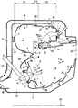
- the space 21 between the outer wall 16 of the casing and the corresponding parts of the wall 6, of the support 2 and of the bottom 5 may contain, as in the example shown, an additional compressor 22; for this purpose, an intermediate wall 23, inside the casing, separates the interior of the latter into two distinct volumes: the space 21, and a space 24, delimited by this intermediate wall 23, the wall 8 and the remaining parts from the bottom 5 and from the wall 6.
- the space 24 is in direct communication with the orifice 18 of the upstream general intake of compressed oxidizer.
- the two extreme operating speeds are that of idling, with only the first fuel injection device 3 in service, and that of full load where the second fuel injection device 10 is also in service.
- the arrangements of the invention shown allow combustion of a rich mixture in the first enclosure 1, which is not very polluting, and stable due to the configuration against the current of the injection (F3) in this enclosure relative to the direction F14. evacuation of burnt gases outside the enclosure 14.
- the primary oxidizer intake devices 4 and 11 can of course be of "variable geometry", that is to say be provided with devices for adjusting their oxidizer intake section, and therefore the flow rate thereof. this.
- the oxidizer necessary for the operation of the "full throttle” head penetrates in a conventional manner from the space 24 while a part of this oxidizer necessary for the operation of the "idle” head is taken from the diffusion space 21.
- the additional compression stage 22 (radial or axial) is possibly adopted, as shown in the drawing.
Landscapes
- Engineering & Computer Science (AREA)
- Chemical & Material Sciences (AREA)
- Combustion & Propulsion (AREA)
- Mechanical Engineering (AREA)
- General Engineering & Computer Science (AREA)
- Combustion Methods Of Internal-Combustion Engines (AREA)
- Fuel-Injection Apparatus (AREA)
- Output Control And Ontrol Of Special Type Engine (AREA)
Applications Claiming Priority (2)
| Application Number | Priority Date | Filing Date | Title |
|---|---|---|---|
| FR9101640A FR2672667B1 (fr) | 1991-02-13 | 1991-02-13 | Chambre de combustion pour turboreacteur a faible niveau d'emissions polluantes. |
| FR9101640 | 1991-02-13 |
Publications (2)
| Publication Number | Publication Date |
|---|---|
| EP0499535A1 true EP0499535A1 (de) | 1992-08-19 |
| EP0499535B1 EP0499535B1 (de) | 1995-01-04 |
Family
ID=9409641
Family Applications (1)
| Application Number | Title | Priority Date | Filing Date |
|---|---|---|---|
| EP92400367A Expired - Lifetime EP0499535B1 (de) | 1991-02-13 | 1992-02-12 | Brennkammer einer Gasturbine mit niedrigem Auspuff-Schadstoffgehalt |
Country Status (5)
| Country | Link |
|---|---|
| US (1) | US5295354A (de) |
| EP (1) | EP0499535B1 (de) |
| JP (1) | JPH04316921A (de) |
| DE (1) | DE69201062T2 (de) |
| FR (1) | FR2672667B1 (de) |
Cited By (2)
| Publication number | Priority date | Publication date | Assignee | Title |
|---|---|---|---|---|
| US12228286B1 (en) | 2023-09-29 | 2025-02-18 | General Electric Company | Combustion section with a primary combustion chamber and a secondary combustion chamber |
| EP4513089A1 (de) * | 2023-08-22 | 2025-02-26 | General Electric Company | Brennkammer |
Families Citing this family (18)
| Publication number | Priority date | Publication date | Assignee | Title |
|---|---|---|---|---|
| DE4318405C2 (de) * | 1993-06-03 | 1995-11-02 | Mtu Muenchen Gmbh | Brennkammeranordnung für eine Gasturbine |
| DE19728375A1 (de) * | 1997-07-03 | 1999-01-07 | Bmw Rolls Royce Gmbh | Betriebsverfahren für eine axial gestufte Brennkammer einer Fluggasturbine |
| RU2176052C2 (ru) * | 1999-12-21 | 2001-11-20 | Открытое акционерное общество "Авиадвигатель" | Камера сгорания турбомашины |
| US7425127B2 (en) * | 2004-06-10 | 2008-09-16 | Georgia Tech Research Corporation | Stagnation point reverse flow combustor |
| US8387390B2 (en) * | 2006-01-03 | 2013-03-05 | General Electric Company | Gas turbine combustor having counterflow injection mechanism |
| EP2372245A1 (de) * | 2010-03-26 | 2011-10-05 | Siemens Aktiengesellschaft | Brenner zur Stabilisierung der Verbrennung einer Gasturbine sowie Verfahren |
| US8522553B2 (en) * | 2011-09-14 | 2013-09-03 | General Electric Company | System and method for conditioning a working fluid in a combustor |
| US9243802B2 (en) | 2011-12-07 | 2016-01-26 | Pratt & Whitney Canada Corp. | Two-stage combustor for gas turbine engine |
| US9416972B2 (en) | 2011-12-07 | 2016-08-16 | Pratt & Whitney Canada Corp. | Two-stage combustor for gas turbine engine |
| US9194586B2 (en) | 2011-12-07 | 2015-11-24 | Pratt & Whitney Canada Corp. | Two-stage combustor for gas turbine engine |
| EP2857658A1 (de) * | 2013-10-01 | 2015-04-08 | Alstom Technology Ltd | Gasturbine mit einer sequentiellen Brennanordnung |
| US10976052B2 (en) * | 2017-10-25 | 2021-04-13 | General Electric Company | Volute trapped vortex combustor assembly |
| US12130016B1 (en) * | 2023-05-31 | 2024-10-29 | General Electric Company | Turbine engine including a combustor |
| US20240401807A1 (en) * | 2023-05-31 | 2024-12-05 | General Electric Company | Turbine engine including a combustor |
| EP4528164A3 (de) * | 2023-09-25 | 2025-04-09 | General Electric Company | Verbrennungsabschnitt mit einer primärbrennkammer und einem satz von sekundärbrennkammern |
| US20250109853A1 (en) * | 2023-09-28 | 2025-04-03 | General Electric Company | Combustion section with a primary combustor and a set of secondary combustors |
| US20260022839A1 (en) * | 2024-07-22 | 2026-01-22 | General Electric Company | Gas turbine engine and fuel nozzle assembly therefor |
| US20260022838A1 (en) * | 2024-07-22 | 2026-01-22 | General Electric Company | Gas turbine engine and fuel nozzle assembly therefor |
Citations (4)
| Publication number | Priority date | Publication date | Assignee | Title |
|---|---|---|---|---|
| DE954465C (de) * | 1954-11-05 | 1956-12-20 | Daimler Benz Ag | Brennkammer, insbesondere fuer kleinere Gasturbinen |
| DE2412120A1 (de) * | 1973-03-13 | 1974-09-19 | Snecma | Umweltfreundliche brennkammer fuer gasturbinen |
| GB2010407A (en) * | 1977-12-01 | 1979-06-27 | United Technologies Corp | Burner for gas turbine engine |
| GB2044433A (en) * | 1978-12-12 | 1980-10-15 | Council Scient Ind Res | Improved gas turbine engines operating on gaseous fuels |
Family Cites Families (3)
| Publication number | Priority date | Publication date | Assignee | Title |
|---|---|---|---|---|
| FR2402068A1 (fr) * | 1977-09-02 | 1979-03-30 | Snecma | Chambre de combustion anti-pollution |
| JPS60240833A (ja) * | 1984-05-15 | 1985-11-29 | Hitachi Ltd | ガスタ−ビン燃焼方法及びガスタ−ビン燃焼器 |
| EP0193029B1 (de) * | 1985-02-26 | 1988-11-17 | BBC Brown Boveri AG | Brennkammer für Gasturbinen |
-
1991
- 1991-02-13 FR FR9101640A patent/FR2672667B1/fr not_active Expired - Fee Related
-
1992
- 1992-02-07 JP JP4022907A patent/JPH04316921A/ja active Pending
- 1992-02-12 DE DE69201062T patent/DE69201062T2/de not_active Expired - Fee Related
- 1992-02-12 EP EP92400367A patent/EP0499535B1/de not_active Expired - Lifetime
- 1992-02-13 US US07/834,820 patent/US5295354A/en not_active Expired - Fee Related
Patent Citations (4)
| Publication number | Priority date | Publication date | Assignee | Title |
|---|---|---|---|---|
| DE954465C (de) * | 1954-11-05 | 1956-12-20 | Daimler Benz Ag | Brennkammer, insbesondere fuer kleinere Gasturbinen |
| DE2412120A1 (de) * | 1973-03-13 | 1974-09-19 | Snecma | Umweltfreundliche brennkammer fuer gasturbinen |
| GB2010407A (en) * | 1977-12-01 | 1979-06-27 | United Technologies Corp | Burner for gas turbine engine |
| GB2044433A (en) * | 1978-12-12 | 1980-10-15 | Council Scient Ind Res | Improved gas turbine engines operating on gaseous fuels |
Cited By (4)
| Publication number | Priority date | Publication date | Assignee | Title |
|---|---|---|---|---|
| EP4513089A1 (de) * | 2023-08-22 | 2025-02-26 | General Electric Company | Brennkammer |
| US12535215B2 (en) | 2023-08-22 | 2026-01-27 | General Electric Company | Combustor including a steam injector operably injecting steam into a trapped vortex cavity |
| US12228286B1 (en) | 2023-09-29 | 2025-02-18 | General Electric Company | Combustion section with a primary combustion chamber and a secondary combustion chamber |
| EP4530533A1 (de) * | 2023-09-29 | 2025-04-02 | General Electric Company | Brennkammer mit einer primärbrennkammer und einer sekundärbrennkammer |
Also Published As
| Publication number | Publication date |
|---|---|
| EP0499535B1 (de) | 1995-01-04 |
| US5295354A (en) | 1994-03-22 |
| FR2672667B1 (fr) | 1994-12-09 |
| DE69201062D1 (de) | 1995-02-16 |
| JPH04316921A (ja) | 1992-11-09 |
| DE69201062T2 (de) | 1995-06-14 |
| FR2672667A1 (fr) | 1992-08-14 |
Similar Documents
| Publication | Publication Date | Title |
|---|---|---|
| EP0499535B1 (de) | Brennkammer einer Gasturbine mit niedrigem Auspuff-Schadstoffgehalt | |
| EP0491625B1 (de) | Umkehrbrennkammer von kurzer Länge mit reduzierter NOx-Produktion | |
| BE1001690A3 (fr) | Moteur equipe pour la detection d'un parametre des gaz d'echappement. | |
| CA2198420C (fr) | Dispositif d'injection de combustible pour statoreacteur d'aeronef | |
| EP0964206B1 (de) | Brennkammer einer Gasturbine mit verstellbarer Geometrie | |
| CA2059789A1 (fr) | Chambre de combustion, notamment pour turbine a gaz, a paroi deformable | |
| FR2636376A1 (fr) | Dispositif de prelevement de gaz chauds dans une chambre de combustion et tete d'injection equipee d'un dispositif de prelevement | |
| EP0501877A1 (de) | Brennkammer mit armer Vormisch- und Gegenstromkammer zur Stabilisierung der Vormischflamme | |
| FR2706021A1 (fr) | Chambre de combustion comprenant un ensemble séparateur de gaz. | |
| FR2525275A1 (fr) | Moteur a combustion interne a allumage par flamme | |
| CA2886298C (fr) | Ensemble de combustion de turbomachine a variation d'alimentation d'air | |
| EP3688294B1 (de) | Brennkammer mit konstantem volumen und zugehöriges turbinenmotorverbrennungssystem | |
| FR2644512A1 (fr) | Dispositif d'ejection d'air pour moteur a deux temps | |
| FR2549897A1 (fr) | Dispositif d'admission pour moteur a combustion interne | |
| EP3788243A1 (de) | Gaseinlassvorrichtung mit einem zur brandfläche geneigten schnittpunkt des einlasskanals und der ventilkalibrierung | |
| FR3114614A1 (fr) | Dispositif d’allumage à préchambre pour moteur à combustion interne à allumage commandé | |
| EP0657699A1 (de) | Gasturbinenbrennkammer mit einem zentralen Schneidering | |
| FR2668798A1 (fr) | Moteur deux temps. | |
| FR2674906A1 (fr) | Moteur a deux temps a controle selectif de la charge introduite dans la chambre de combustion. | |
| EP0565442A1 (de) | Brennkammerwand | |
| EP0754268B1 (de) | Zweitakt dieselbrennkraftmaschine mit einem spiralförmigen luftanzugskanal | |
| FR2801638A1 (fr) | Systeme d'admission de gaz dans un moteur a combustion | |
| FR2487009A1 (fr) | Moteur a combustion interne equipe d'un circuit secondaire d'admission | |
| FR2531139A1 (fr) | Dispositif de controle d'un circuit de gaz d'une chambre de combustion | |
| WO2025186224A1 (fr) | Agencement comprenant une culasse et une bougie d'allumage pour moteur à allumage commandé |
Legal Events
| Date | Code | Title | Description |
|---|---|---|---|
| PUAI | Public reference made under article 153(3) epc to a published international application that has entered the european phase |
Free format text: ORIGINAL CODE: 0009012 |
|
| 17P | Request for examination filed |
Effective date: 19920302 |
|
| AK | Designated contracting states |
Kind code of ref document: A1 Designated state(s): DE FR GB IT |
|
| 17Q | First examination report despatched |
Effective date: 19931201 |
|
| GRAA | (expected) grant |
Free format text: ORIGINAL CODE: 0009210 |
|
| AK | Designated contracting states |
Kind code of ref document: B1 Designated state(s): DE FR GB IT |
|
| PG25 | Lapsed in a contracting state [announced via postgrant information from national office to epo] |
Ref country code: IT Free format text: LAPSE BECAUSE OF FAILURE TO SUBMIT A TRANSLATION OF THE DESCRIPTION OR TO PAY THE FEE WITHIN THE PRESCRIBED TIME-LIMIT;WARNING: LAPSES OF ITALIAN PATENTS WITH EFFECTIVE DATE BEFORE 2007 MAY HAVE OCCURRED AT ANY TIME BEFORE 2007. THE CORRECT EFFECTIVE DATE MAY BE DIFFERENT FROM THE ONE RECORDED. Effective date: 19950104 |
|
| REF | Corresponds to: |
Ref document number: 69201062 Country of ref document: DE Date of ref document: 19950216 |
|
| GBT | Gb: translation of ep patent filed (gb section 77(6)(a)/1977) |
Effective date: 19950130 |
|
| PLBE | No opposition filed within time limit |
Free format text: ORIGINAL CODE: 0009261 |
|
| STAA | Information on the status of an ep patent application or granted ep patent |
Free format text: STATUS: NO OPPOSITION FILED WITHIN TIME LIMIT |
|
| 26N | No opposition filed | ||
| PGFP | Annual fee paid to national office [announced via postgrant information from national office to epo] |
Ref country code: FR Payment date: 19990121 Year of fee payment: 8 |
|
| PGFP | Annual fee paid to national office [announced via postgrant information from national office to epo] |
Ref country code: GB Payment date: 19990211 Year of fee payment: 8 |
|
| PGFP | Annual fee paid to national office [announced via postgrant information from national office to epo] |
Ref country code: DE Payment date: 19990429 Year of fee payment: 8 |
|
| PG25 | Lapsed in a contracting state [announced via postgrant information from national office to epo] |
Ref country code: GB Free format text: LAPSE BECAUSE OF NON-PAYMENT OF DUE FEES Effective date: 20000212 |
|
| GBPC | Gb: european patent ceased through non-payment of renewal fee |
Effective date: 20000212 |
|
| PG25 | Lapsed in a contracting state [announced via postgrant information from national office to epo] |
Ref country code: FR Free format text: LAPSE BECAUSE OF NON-PAYMENT OF DUE FEES Effective date: 20001031 |
|
| PG25 | Lapsed in a contracting state [announced via postgrant information from national office to epo] |
Ref country code: DE Free format text: LAPSE BECAUSE OF NON-PAYMENT OF DUE FEES Effective date: 20001201 |
|
| REG | Reference to a national code |
Ref country code: FR Ref legal event code: ST |