EP0499652A1 - Drehmaschine zur Erzeugen asphärischer Oberflächen auf Werkstücken - Google Patents
Drehmaschine zur Erzeugen asphärischer Oberflächen auf Werkstücken Download PDFInfo
- Publication number
- EP0499652A1 EP0499652A1 EP91102216A EP91102216A EP0499652A1 EP 0499652 A1 EP0499652 A1 EP 0499652A1 EP 91102216 A EP91102216 A EP 91102216A EP 91102216 A EP91102216 A EP 91102216A EP 0499652 A1 EP0499652 A1 EP 0499652A1
- Authority
- EP
- European Patent Office
- Prior art keywords
- cam
- cam follower
- assembly
- axis
- spindle
- Prior art date
- Legal status (The legal status is an assumption and is not a legal conclusion. Google has not performed a legal analysis and makes no representation as to the accuracy of the status listed.)
- Granted
Links
- 238000005520 cutting process Methods 0.000 claims abstract description 26
- 238000006073 displacement reaction Methods 0.000 claims description 7
- 230000020347 spindle assembly Effects 0.000 claims description 6
- 230000000694 effects Effects 0.000 abstract description 6
- 230000003287 optical effect Effects 0.000 description 6
- 230000007812 deficiency Effects 0.000 description 2
- 230000000712 assembly Effects 0.000 description 1
- 238000000429 assembly Methods 0.000 description 1
- 230000001276 controlling effect Effects 0.000 description 1
- 230000002079 cooperative effect Effects 0.000 description 1
- 230000001419 dependent effect Effects 0.000 description 1
Images

Classifications
-
- B—PERFORMING OPERATIONS; TRANSPORTING
- B23—MACHINE TOOLS; METAL-WORKING NOT OTHERWISE PROVIDED FOR
- B23Q—DETAILS, COMPONENTS, OR ACCESSORIES FOR MACHINE TOOLS, e.g. ARRANGEMENTS FOR COPYING OR CONTROLLING; MACHINE TOOLS IN GENERAL CHARACTERISED BY THE CONSTRUCTION OF PARTICULAR DETAILS OR COMPONENTS; COMBINATIONS OR ASSOCIATIONS OF METAL-WORKING MACHINES, NOT DIRECTED TO A PARTICULAR RESULT
- B23Q35/00—Control systems or devices for copying directly from a pattern or a master model; Devices for use in copying manually
- B23Q35/04—Control systems or devices for copying directly from a pattern or a master model; Devices for use in copying manually using a feeler or the like travelling along the outline of the pattern, model or drawing; Feelers, patterns, or models therefor
- B23Q35/24—Feelers; Feeler units
- B23Q35/26—Feelers; Feeler units designed for a physical contact with a pattern or a model
-
- B—PERFORMING OPERATIONS; TRANSPORTING
- B23—MACHINE TOOLS; METAL-WORKING NOT OTHERWISE PROVIDED FOR
- B23Q—DETAILS, COMPONENTS, OR ACCESSORIES FOR MACHINE TOOLS, e.g. ARRANGEMENTS FOR COPYING OR CONTROLLING; MACHINE TOOLS IN GENERAL CHARACTERISED BY THE CONSTRUCTION OF PARTICULAR DETAILS OR COMPONENTS; COMBINATIONS OR ASSOCIATIONS OF METAL-WORKING MACHINES, NOT DIRECTED TO A PARTICULAR RESULT
- B23Q35/00—Control systems or devices for copying directly from a pattern or a master model; Devices for use in copying manually
- B23Q35/04—Control systems or devices for copying directly from a pattern or a master model; Devices for use in copying manually using a feeler or the like travelling along the outline of the pattern, model or drawing; Feelers, patterns, or models therefor
- B23Q35/08—Means for transforming movement of the feeler or the like into feed movement of tool or work
- B23Q35/10—Means for transforming movement of the feeler or the like into feed movement of tool or work mechanically only
- B23Q35/101—Means for transforming movement of the feeler or the like into feed movement of tool or work mechanically only with a pattern composed of one or more lines used simultaneously for one tool
- B23Q35/102—Means for transforming movement of the feeler or the like into feed movement of tool or work mechanically only with a pattern composed of one or more lines used simultaneously for one tool of one line
-
- B—PERFORMING OPERATIONS; TRANSPORTING
- B24—GRINDING; POLISHING
- B24B—MACHINES, DEVICES, OR PROCESSES FOR GRINDING OR POLISHING; DRESSING OR CONDITIONING OF ABRADING SURFACES; FEEDING OF GRINDING, POLISHING, OR LAPPING AGENTS
- B24B13/00—Machines or devices designed for grinding or polishing optical surfaces on lenses or surfaces of similar shape on other work; Accessories therefor
- B24B13/04—Machines or devices designed for grinding or polishing optical surfaces on lenses or surfaces of similar shape on other work; Accessories therefor grinding of lenses involving grinding wheels controlled by gearing
- B24B13/046—Machines or devices designed for grinding or polishing optical surfaces on lenses or surfaces of similar shape on other work; Accessories therefor grinding of lenses involving grinding wheels controlled by gearing using a pointed tool or scraper-like tool
-
- Y—GENERAL TAGGING OF NEW TECHNOLOGICAL DEVELOPMENTS; GENERAL TAGGING OF CROSS-SECTIONAL TECHNOLOGIES SPANNING OVER SEVERAL SECTIONS OF THE IPC; TECHNICAL SUBJECTS COVERED BY FORMER USPC CROSS-REFERENCE ART COLLECTIONS [XRACs] AND DIGESTS
- Y10—TECHNICAL SUBJECTS COVERED BY FORMER USPC
- Y10T—TECHNICAL SUBJECTS COVERED BY FORMER US CLASSIFICATION
- Y10T82/00—Turning
- Y10T82/13—Pattern section
- Y10T82/135—Cam-controlled cutter
-
- Y—GENERAL TAGGING OF NEW TECHNOLOGICAL DEVELOPMENTS; GENERAL TAGGING OF CROSS-SECTIONAL TECHNOLOGIES SPANNING OVER SEVERAL SECTIONS OF THE IPC; TECHNICAL SUBJECTS COVERED BY FORMER USPC CROSS-REFERENCE ART COLLECTIONS [XRACs] AND DIGESTS
- Y10—TECHNICAL SUBJECTS COVERED BY FORMER USPC
- Y10T—TECHNICAL SUBJECTS COVERED BY FORMER US CLASSIFICATION
- Y10T82/00—Turning
- Y10T82/14—Axial pattern
- Y10T82/148—Pivoted tool rest
Definitions
- This invention relates in general to a lathe for generating aspherical surfaces on work pieces and in particular generating such surfaces of revolution on a front surface of an optical lens blank.
- Optical lenses designed for correcting vision deficiencies of persons have been developed and utilized for a long period of time. As is the case with any optical lens, it is necessary to generate surfaces, both front and rear, of predetermined configuration to effect a desired correction of a particular patient's vision deficiency. It is a common practice to utilize an apparatus which is of a machine lathe type structure wherein the lens blank is mounted on a spindle which is revolved while a cutting tool is applied to the surface for generating of a specific configuration.
- An example of such a prior art lathe is disclosed in U. S. Patent No. 3,977,279 issued August 31, 1976 to Derrell C. Hooker.
- the lathe disclosed in that patent in general, comprises a spindle for supporting the lens blank and rotation thereof during surface forming operations and a cutting tool carried on a turret device that is rotatable about an axis transverse to the axis of rotation of the lens supporting spindle.
- Control mechanism is provided to effect relative displacement of tie cutting tool in a predetermined manner during the surface generating operation.
- This control mechanism includes a concave cam surface against which a spring-biased tool support and cam follower cooperate in effecting this control over the surface to be generated.
- the surfaces that can be generated by the Hooker lathe may be of not only an aspherical configuration, but may also be spherical. The particular configuration is dependent upon the settings of the various components of the apparatus and particularly as to the control elements.
- the present invention provides an improved lathe having superior capabilities of generating desired surfaces on work pieces such as contact lens blanks.
- the improved lathe includes the general basic components of a rotatable spindle for supporting the lens blank, a turret assembly carrying the lens cutting tool and a control cam assembly.
- the control cam assembly supports a roller cam in a predetermined position with respect to the turret assembly.
- Mounted on the turret assembly is a cutting tool support that not only carries the cutting tool, but also carries a cam follower.
- the supports for the cutting tool and cam follower are spring-biased to maintain the follower in engagement with the roller cam as the turret assembly is revolved in effecting a cutting operation.
- the cam follower has a V-shaped configuration including divergent side walls that extend at a predetermined angle to each other and from an apex that has a small radius curvature.
- the roller cam is positioned at a predetermined point with respect to the axis of rotation of the turret assembly.
- the cutting tool and cam follower supports are relatively adjustable and positionable on the turret assembly. They are prepositioned with respect to the axis of rotation of the turret assembly in accordance with the position of the roller cam and are set to develop or generate a predetermined surface on the lens blank.
- the improved structure of the cam and cam follower in the lathe of this invention are capable of effecting a precise surface configuration which, in the case of a contact lens, is of an optic design that is necessary to effect the appropriate correction for a particular patient. Additionally, the improved cam and cam follower mechanism are capable of controlling the generation of the surface to a desired shape without discontinuities throughout the extent of the optically effective portion and thereby avoid any discontinuities in the area or region of the lens that effects the optical correction.
- One aspect of this invention is a lathe for generating surfaces of revolution on a work piece
- a lathe for generating surfaces of revolution on a work piece
- a base comprising a base; a spindle assembly mounted on said base and including an elongated, rotatably supported spindle having a longitudinal axis and an end for mounting of a work piece thereon and means for rotating said spindle, said spindle axis being disposed in a predetermined plane; a turret assembly mounted on said base and including a rotatable base mount for pivotally supporting said turret assembly for revolution about a vertical axis of rotation disposed transversely to said spindle axis, a cam follower and cutting tool support assembly secured to said base mount for relative displacement along an axis of displacement in a plane disposed in transverse relationship to said vertical axis of rotation of said turret assembly, a cam follower having an end portion of V-shaped configuration having an apex and side walls divergent from said
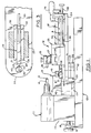
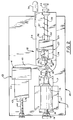
- FIGURE 1 is a side elevational view of a lathe embodying this invention.
- FIGURE 2 is a top plan view of the lathe.
- FIGURE 3 is a fragmentary sectional view taken along line 3-3 of FIGURE 1.
- FIGURE 4 is a medial cross-sectional view of a contact lens having surfaces generated by the lathe apparatus.
- FIGURES 5 and 6 are sequential diagrammatic illustrations of the relative positioning of the cam and cam follower as results from revolution of the turret assembly.
- the lathe apparatus is seen to include as the basic component a base 10, spindle assembly 11, turret assembly 12 and control cam assembly 13. Each of the spindle, turret and control cam assemblies 11, 12 and 13 are mounted on the base 10.
- the spindle assembly. 11 includes a mounting frame 14 carrying at its upper side a spindle support drive 15 that has an elongated spindle 16 adapted to carry a work piece such as a lens blank L at its free end. As is conventional in a lathe of this type, the spindle 16 is supported for rotation about a horizontal axis.
- a drive mechanism of a type generally utilized in lens cutting apparatus of this nature is also included in the spindle support drive 15 but not specifically illustrated, and may include a gear mechanism capable of obtaining different rotational speeds as between an electric drive motor and the spindle 16.
- Such components are well-known to those skilled in this particular art and thus they are not illustrated in further detail.
- the mounting frame 14 in this lathe apparatus is of a type that permits selective adjustment of its position on the base along an axis that parallels the spindle.
- This adjusting mechanism includes cooperating guide ways 17 fixed on the top surface of the base 10 and formed in the lower portion of the mounting frame 14.
- a screw thread adjusting device 18 is provided and manually operable through a hand wheel 19 to effect positioning of the spindle assembly 11 at a desired point.
- This turret assembly 12 Displaced from the spindle assembly 11 is the turret assembly 12 and it is positioned along the longitudinal axis of the spindle.
- This turret assembly 12 includes a rotatable base mount 20 having a vertical pivot axis designated as 21.
- This rotatable base mount 20 includes a bottom portion 22 which is adapted to be fixed to the upper surface of the base and an upper section that is relatively rotatable with respect to the bottom.
- Secured to the upper section 23 is an elongated mounting plate 24.
- Mounted on the plate 24 is a cam follower and cutting tool support assembly 25.
- This support assembly 25 includes a cam follower mechanism 26 which is disposed next above the mounting plate 24 and a cutting tool holder 27.
- the cam follower mechanism 26 comprises a cam follower 28 that includes as its basic component a flat plate having an end portion formed with side walls 29 that converge toward an apex 30 as can be best seen in FIGURE 3. These side walls 29 are interconnected by the generally circularly-shaped apex 30 which has a relatively small radius. Also included in the cam follower mechanism 26 are guide way plates 32 which mechanically interengage with the cam follower and permit its axial reciprocation. A screw thread adjustment mechanism 33 is provided to position the cam follower with respect to the mounting plate and to maintain tie follower in the selected position.
- the cutting tool holder includes an interconnecting mechanism to permit relative adjustment of the holder with respect to the cam follower mechanism.
- This cutting tool holder also includes a transverse slide support 34 that has a tool clamp 35 and carries the cutting tool 36 adjustable with respect to the turret assembly 12.
- a spring biasing mechanism 37 is provided and mechanically interconnected as between the mounting plate 24 and the cam follower and cutting tool support assembly 25.
- This biasing mechanism includes a resilient spring device 38 which is operational to urge the cam follower and associated components in a direction that is generally toward the spindle. Operation of the turret assembly essentially consists of rotating the turret assembly about its vertical axis 21. This causes the cutting point of the tool 36 to swing across the forward face of the lens blank L and to thereby cut the desired surface. Manual operation of the turret assembly is facilitated by means of a handle 39.
- the control cam assembly 13 includes as its primary component a cam having a convexly arcuate camming surface and which, in this illustrative embodiment, is a roller cam 40 having a cylindrical cam surface that is circular.
- This roller cam is mounted on a support assembly 41 with its axis of rotation vertically oriented to be parallel to the axis of rotation of the turret assembly.
- a frame structure which is of an adjustable type to permit both longitudinal and transverse positioning of the roller cam 40.
- Forming the adjustable structure is a base member 42 secured to the base 10 through a guide way 43.
- the base member 42 is adjustable longitudinally of the base and parallel to toe spindle 16 through a screw thread adjusting mechanism 44.
- an elongated support arm 45 Secured to the base member 42 is an elongated support arm 45 to which the roller cam 40 is journalled at its one end.
- the arm itself is slideably secured in a guide way formed in the base member 42 and is transversely adjustable to a desired position with respect to the base member.
- This adjustment mechanism permits the roller cam 40 to be relatively positioned as to the axis 21 of the turret assembly to enable the lathe to be utilized in forming of any particular and desired surface configuration on the lens blank.
- This adjustment is in cooperation with the positioning of the cam follower 28 and enables the operator to obtain the desired lens curvature.
- Relative positioning of the axes 21 of the turret assembly and that of the roller cam which is designated as 46 in FIGURES 5 and 6 can be seen to be relatively adjustable both in a longitudinal direction as well as a transverse direction.
- FIGURES 5 and 6 diagrammatically illustrate the functioning of the cam follower 28 with respect to the cam roller 40.
- the axis 46 of the cam roller is located along the longitudinal axis of the lathe and which longitudinal axis is extending through the vertical axis 21 of the turret assembly, but is spaced with respect to the turret axis 21.
- the turret assembly is operated to swing the cutting tool 36 along a predetermined path with that path being determined by the cooperative action of the forward end of a cam follower 28 relative to the circular surface of the cam roller 40.
- FIGURE 4 A shape that can be developed for a contact lens is diagrammatically illustrated in FIGURE 4.
- FIGURE 4 A shape that can be developed for a contact lens is diagrammatically illustrated in FIGURE 4.
- the lens is seen to have a rear spherical surface designated by the letter S having a radius R and a front surface designated by the letter F.
- a lens configuration that can be developed by the lathe of this invention is a front surface F having a configuration which, throughout the extent of effective optical operating range, which range is generally indicated by an arc A, results in a lens that has a constant thickness T throughout the extent of its operating range. Variations in the thickness T result in different optical characteristics as determined in accordance with the particular patient's requirements.
Landscapes
- Engineering & Computer Science (AREA)
- Mechanical Engineering (AREA)
- Automation & Control Theory (AREA)
- Turning (AREA)
Priority Applications (1)
| Application Number | Priority Date | Filing Date | Title |
|---|---|---|---|
| DE1991610122 DE69110122T2 (de) | 1991-02-16 | 1991-02-16 | Drehmaschine zur Erzeugen asphärischer Oberflächen auf Werkstücken. |
Applications Claiming Priority (1)
| Application Number | Priority Date | Filing Date | Title |
|---|---|---|---|
| US07/345,418 US4995300A (en) | 1989-04-28 | 1989-04-28 | Lathe for generating aspherical surfaces on work pieces |
Publications (2)
| Publication Number | Publication Date |
|---|---|
| EP0499652A1 true EP0499652A1 (de) | 1992-08-26 |
| EP0499652B1 EP0499652B1 (de) | 1995-05-31 |
Family
ID=23354964
Family Applications (1)
| Application Number | Title | Priority Date | Filing Date |
|---|---|---|---|
| EP91102216A Expired - Lifetime EP0499652B1 (de) | 1989-04-28 | 1991-02-16 | Drehmaschine zur Erzeugen asphärischer Oberflächen auf Werkstücken |
Country Status (2)
| Country | Link |
|---|---|
| US (1) | US4995300A (de) |
| EP (1) | EP0499652B1 (de) |
Families Citing this family (8)
| Publication number | Priority date | Publication date | Assignee | Title |
|---|---|---|---|---|
| JP3026824B2 (ja) * | 1990-07-31 | 2000-03-27 | 株式会社メニコン | 非球面レンズの製造装置 |
| US5502518A (en) * | 1993-09-09 | 1996-03-26 | Scient Optics Inc | Asymmetric aspheric contact lens |
| US5842395A (en) * | 1996-11-20 | 1998-12-01 | Hall; Larry Gene | Lathe for producing an aspherical surface on an optical lens blank |
| US6237453B1 (en) * | 1999-10-18 | 2001-05-29 | C.J. Winter Machine Technologies, Inc. | Two position tool slide for screw machine |
| DE102004049951A1 (de) * | 2004-10-13 | 2006-04-20 | Schneider Gmbh + Co. Kg | Hochdynamische Linsenbearbeitungsmaschine |
| CN101829790B (zh) * | 2010-04-12 | 2011-08-10 | 厦门大学 | 一种小型非球面光学元件的车削加工方法 |
| CN105583685B (zh) * | 2014-10-24 | 2018-05-04 | 富鼎电子科技(嘉善)有限公司 | 刹车机构及采用该刹车机构的加工装置 |
| KR20170129163A (ko) * | 2015-02-24 | 2017-11-24 | 반두리트 게엠베하 하르트메탈 운트 디아만트베르크초이그 | 회전 피가공재를 기계가공하기 위한 디바이스, 방법 및 절단 플레이트 |
Citations (5)
| Publication number | Priority date | Publication date | Assignee | Title |
|---|---|---|---|---|
| GB604889A (en) * | 1945-12-07 | 1948-07-12 | Engineering Diamonds Ltd | Improvements in or relating to forming and cutting tools |
| US3301104A (en) * | 1965-01-29 | 1967-01-31 | Philip R Matlack | Apparatus for turning curved surfaces |
| FR2212772A5 (de) * | 1972-12-29 | 1974-07-26 | Bettiol Bruno | |
| US3977279A (en) * | 1975-04-16 | 1976-08-31 | Derrell C. Hooker | Lathe for generating spherical or aspherical surfaces on workpieces |
| US4114486A (en) * | 1975-04-16 | 1978-09-19 | Aspheric Associates, Ltd. | Lathe for generating spherical or aspherical surfaces on workpieces, method for generating aspherical surfaces on workpieces and workpiece having aspherical surface |
Family Cites Families (7)
| Publication number | Priority date | Publication date | Assignee | Title |
|---|---|---|---|---|
| US3983770A (en) * | 1975-10-30 | 1976-10-05 | F. Jos. Lamb Company | Piston turning machine |
| US4302992A (en) * | 1980-01-17 | 1981-12-01 | F. Jos. Lamb Company | Piston turning machine |
| EP0065993B1 (de) * | 1980-12-11 | 1991-11-21 | Matsushita Electric Industrial Co., Ltd. | Antriebsvorrichtung für kopiernocken einer werkzeugmaschine |
| GB8325027D0 (en) * | 1983-09-19 | 1983-10-19 | Robertson Eng Thame Ltd | Aspheric cutting lathe |
| US4553767A (en) * | 1984-02-09 | 1985-11-19 | The Quaker Oats Company | Roller skate with integral ratchet means |
| US4680998A (en) * | 1984-08-28 | 1987-07-21 | Bausch & Lomb Incorporated | Toric lenses, method and apparatus for making same |
| US4852436A (en) * | 1987-11-16 | 1989-08-01 | Hughes Aircraft Company | Cam-controlled turning machine |
-
1989
- 1989-04-28 US US07/345,418 patent/US4995300A/en not_active Expired - Fee Related
-
1991
- 1991-02-16 EP EP91102216A patent/EP0499652B1/de not_active Expired - Lifetime
Patent Citations (5)
| Publication number | Priority date | Publication date | Assignee | Title |
|---|---|---|---|---|
| GB604889A (en) * | 1945-12-07 | 1948-07-12 | Engineering Diamonds Ltd | Improvements in or relating to forming and cutting tools |
| US3301104A (en) * | 1965-01-29 | 1967-01-31 | Philip R Matlack | Apparatus for turning curved surfaces |
| FR2212772A5 (de) * | 1972-12-29 | 1974-07-26 | Bettiol Bruno | |
| US3977279A (en) * | 1975-04-16 | 1976-08-31 | Derrell C. Hooker | Lathe for generating spherical or aspherical surfaces on workpieces |
| US4114486A (en) * | 1975-04-16 | 1978-09-19 | Aspheric Associates, Ltd. | Lathe for generating spherical or aspherical surfaces on workpieces, method for generating aspherical surfaces on workpieces and workpiece having aspherical surface |
Also Published As
| Publication number | Publication date |
|---|---|
| US4995300A (en) | 1991-02-26 |
| EP0499652B1 (de) | 1995-05-31 |
Similar Documents
| Publication | Publication Date | Title |
|---|---|---|
| US2633675A (en) | Surfacing machine | |
| US4084459A (en) | Method and apparatus for lens turning | |
| US5024024A (en) | Grinding and finishing apparatus and method | |
| CN1857835A (zh) | 用于机加工光学工件、尤其是塑料眼镜片的机床 | |
| US4995300A (en) | Lathe for generating aspherical surfaces on work pieces | |
| JP2004298985A (ja) | レンズ球面研磨装置 | |
| KR101293657B1 (ko) | 안경 렌즈를 천공하는 도구의 천공 방향을 조절하는 장치및 방법 | |
| GB2056895A (en) | Toric surface generator | |
| EP0714577B1 (de) | Gravurkopf mit in einer kartusche montierten komponenten | |
| US4679471A (en) | Lathe for generating aspherical surfaces | |
| US4658549A (en) | Drill bit sharpening device | |
| US4261674A (en) | Gear cutting machine and method | |
| EP0012553A1 (de) | Werkzeugmaschine mit schwenkbarer, senkrechter Spindel und mit schwenkbarer, automatischer Werkzeugwechseleinrichtung | |
| GB2182786A (en) | Microtome having specimen holder movable in two directions | |
| US4166342A (en) | Toroidal polisher | |
| US4817338A (en) | Grinding head for a machine for grinding helically grooved cutting tools | |
| JP3686393B2 (ja) | ルータ研磨機 | |
| CA2036590C (en) | Lathe for generating asperical surface on work pieces | |
| US4535575A (en) | Mounting apparatus for processing lens blanks | |
| US5181345A (en) | Lens grinding method and apparatus | |
| US4769953A (en) | Lens generating system | |
| EP0453094B1 (de) | Verfahren und Gerät zum Schleifen von Linsen | |
| GB1585152A (en) | Method and apparatus for profiling a grinding wheel | |
| US3883994A (en) | Profile grinding apparatus | |
| US6279424B1 (en) | Machine for machining workpieces with cutting teeth, especially saw blades |
Legal Events
| Date | Code | Title | Description |
|---|---|---|---|
| PUAI | Public reference made under article 153(3) epc to a published international application that has entered the european phase |
Free format text: ORIGINAL CODE: 0009012 |
|
| AK | Designated contracting states |
Kind code of ref document: A1 Designated state(s): CH DE ES FR GB IT LI NL SE |
|
| 17P | Request for examination filed |
Effective date: 19930226 |
|
| 17Q | First examination report despatched |
Effective date: 19930716 |
|
| GRAA | (expected) grant |
Free format text: ORIGINAL CODE: 0009210 |
|
| AK | Designated contracting states |
Kind code of ref document: B1 Designated state(s): CH DE ES FR GB IT LI NL SE |
|
| PG25 | Lapsed in a contracting state [announced via postgrant information from national office to epo] |
Ref country code: ES Free format text: THE PATENT HAS BEEN ANNULLED BY A DECISION OF A NATIONAL AUTHORITY Effective date: 19950531 Ref country code: NL Free format text: LAPSE BECAUSE OF FAILURE TO SUBMIT A TRANSLATION OF THE DESCRIPTION OR TO PAY THE FEE WITHIN THE PRESCRIBED TIME-LIMIT Effective date: 19950531 Ref country code: CH Effective date: 19950531 Ref country code: LI Effective date: 19950531 |
|
| RAP3 | Party data changed (applicant data changed or rights of an application transferred) |
Owner name: CHARIOTSTAR, INC. |
|
| REF | Corresponds to: |
Ref document number: 69110122 Country of ref document: DE Date of ref document: 19950706 |
|
| ITF | It: translation for a ep patent filed | ||
| PG25 | Lapsed in a contracting state [announced via postgrant information from national office to epo] |
Ref country code: SE Effective date: 19950831 |
|
| REG | Reference to a national code |
Ref country code: CH Ref legal event code: PL |
|
| ET | Fr: translation filed | ||
| NLV1 | Nl: lapsed or annulled due to failure to fulfill the requirements of art. 29p and 29m of the patents act | ||
| PLBE | No opposition filed within time limit |
Free format text: ORIGINAL CODE: 0009261 |
|
| STAA | Information on the status of an ep patent application or granted ep patent |
Free format text: STATUS: NO OPPOSITION FILED WITHIN TIME LIMIT |
|
| 26N | No opposition filed | ||
| REG | Reference to a national code |
Ref country code: GB Ref legal event code: IF02 |
|
| PGFP | Annual fee paid to national office [announced via postgrant information from national office to epo] |
Ref country code: IT Payment date: 20080228 Year of fee payment: 18 Ref country code: GB Payment date: 20080222 Year of fee payment: 18 Ref country code: DE Payment date: 20080229 Year of fee payment: 18 |
|
| PGFP | Annual fee paid to national office [announced via postgrant information from national office to epo] |
Ref country code: FR Payment date: 20080227 Year of fee payment: 18 |
|
| GBPC | Gb: european patent ceased through non-payment of renewal fee |
Effective date: 20090216 |
|
| REG | Reference to a national code |
Ref country code: FR Ref legal event code: ST Effective date: 20091030 |
|
| PG25 | Lapsed in a contracting state [announced via postgrant information from national office to epo] |
Ref country code: DE Free format text: LAPSE BECAUSE OF NON-PAYMENT OF DUE FEES Effective date: 20090901 |
|
| PG25 | Lapsed in a contracting state [announced via postgrant information from national office to epo] |
Ref country code: FR Free format text: LAPSE BECAUSE OF NON-PAYMENT OF DUE FEES Effective date: 20090302 Ref country code: GB Free format text: LAPSE BECAUSE OF NON-PAYMENT OF DUE FEES Effective date: 20090216 |
|
| PG25 | Lapsed in a contracting state [announced via postgrant information from national office to epo] |
Ref country code: IT Free format text: LAPSE BECAUSE OF NON-PAYMENT OF DUE FEES Effective date: 20090216 |