EP0499718B1 - Set of tubes intended for peritoneal dialysis - Google Patents
Set of tubes intended for peritoneal dialysis Download PDFInfo
- Publication number
- EP0499718B1 EP0499718B1 EP91122356A EP91122356A EP0499718B1 EP 0499718 B1 EP0499718 B1 EP 0499718B1 EP 91122356 A EP91122356 A EP 91122356A EP 91122356 A EP91122356 A EP 91122356A EP 0499718 B1 EP0499718 B1 EP 0499718B1
- Authority
- EP
- European Patent Office
- Prior art keywords
- tube
- fluid communication
- patient
- channel
- connector
- Prior art date
- Legal status (The legal status is an assumption and is not a legal conclusion. Google has not performed a legal analysis and makes no representation as to the accuracy of the status listed.)
- Expired - Lifetime
Links
- 238000000502 dialysis Methods 0.000 title claims description 6
- 239000000385 dialysis solution Substances 0.000 claims description 30
- 238000004891 communication Methods 0.000 claims description 28
- 239000012530 fluid Substances 0.000 claims description 27
- 238000005192 partition Methods 0.000 claims description 12
- 210000002445 nipple Anatomy 0.000 claims description 5
- 238000010276 construction Methods 0.000 claims description 3
- 239000002699 waste material Substances 0.000 claims description 3
- 210000003200 peritoneal cavity Anatomy 0.000 claims description 2
- 230000000295 complement effect Effects 0.000 claims 1
- 239000000243 solution Substances 0.000 description 5
- 210000003734 kidney Anatomy 0.000 description 2
- 102000009123 Fibrin Human genes 0.000 description 1
- 108010073385 Fibrin Proteins 0.000 description 1
- BWGVNKXGVNDBDI-UHFFFAOYSA-N Fibrin monomer Chemical compound CNC(=O)CNC(=O)CN BWGVNKXGVNDBDI-UHFFFAOYSA-N 0.000 description 1
- 210000003567 ascitic fluid Anatomy 0.000 description 1
- 238000005452 bending Methods 0.000 description 1
- 230000000903 blocking effect Effects 0.000 description 1
- 239000008280 blood Substances 0.000 description 1
- 210000004369 blood Anatomy 0.000 description 1
- 230000009977 dual effect Effects 0.000 description 1
- 229950003499 fibrin Drugs 0.000 description 1
- 238000011010 flushing procedure Methods 0.000 description 1
- 230000005484 gravity Effects 0.000 description 1
- 238000001631 haemodialysis Methods 0.000 description 1
- 239000007788 liquid Substances 0.000 description 1
Images


Classifications
-
- A—HUMAN NECESSITIES
- A61—MEDICAL OR VETERINARY SCIENCE; HYGIENE
- A61M—DEVICES FOR INTRODUCING MEDIA INTO, OR ONTO, THE BODY; DEVICES FOR TRANSDUCING BODY MEDIA OR FOR TAKING MEDIA FROM THE BODY; DEVICES FOR PRODUCING OR ENDING SLEEP OR STUPOR
- A61M1/00—Suction or pumping devices for medical purposes; Devices for carrying-off, for treatment of, or for carrying-over, body-liquids; Drainage systems
- A61M1/14—Dialysis systems; Artificial kidneys; Blood oxygenators ; Reciprocating systems for treatment of body fluids, e.g. single needle systems for hemofiltration or pheresis
- A61M1/28—Peritoneal dialysis ; Other peritoneal treatment, e.g. oxygenation
Definitions
- the present invention relates to a set of tubes intended for peritoneal dialysis comprising a patient tube having a first end which is provided with a connector assembly for fluid communication with the patient's peritoneal cavity, and a second end for fluid communication with a supply tube for supply of fresh dialysis solution and a discharge tube for discharge of spent dialysis solution.
- Peritoneal dialysis is a well-known and, for a long time, proven alternative to haemodialysis for cleansing of the blood of patients who have failing kidneys or whose kidneys do not function at all.
- Examples of various systems and apparatus intended for peritoneal dialysis can be found in, for example, EP-A-0 335 814, WO-A-84/02277, GB-A-2 009 619, US-A-Re 32 303 and US-A-4 252 115.
- peritoneal catheters of the type which are described in, for example, WO-A-86/06282 and US-A-4 935 004.
- connection of the different systems to the peritoneal catheter can be carried out with the help of connectors, for example, of the type described in US-A-4 636 204.
- a longer or shorter patient tube forms a part of all systems, which tube attaches the patient's peritoneal catheter to the rest of the system. For the patient's comfort, this patient tube is often given a length of 2-3 meters. In this way, a considerable return of already used or spent dialysis solution results at each change of solution.
- US-A-4 950 259 discloses a double lumen peritoneal catheter including an outer tube and an inner tube fully contained within the lumen of the outer tube and able to move freely within the outer lumen.
- An inflow connector tube is attached to the inner tube and an outflow connector tube is attached to the outer tube.
- the outer tube is perforated to allow inflow of peritoneal fluid.
- This dual lumen catheter permits continous flushing, which should inhibit fibrin accumuluation reducing the risk of blockage of the perforations and tubal lumens.
- the present invention is intended to solve the above mentioned problems and this is achieved in that the patient tube is provided with a double lumen construction along at least a part of its length with a first channel for the fresh dialysis solution and a second channel for the spent dialysis solution, and in that the patient tube comprises a chamber connected to both the first channel and the second channel and positioned adjacent the first end of the patient tube closest to the patient.
- the patient tube normally comprises an inlet connector or similar for fluid communication with the supply tube and the discharge tube.
- this inlet connector is provided with an inlet means for fluid communication between said supply tube and said first channel and an outlet means for fluid communication between said discharge tube and said second channel.
- the same operation can be achieved with the help of a suitable valve construction.
- the first end of the patient tube normally comprises a connector assembly piece provided with said chamber, a connector arrangement for connection to a patient's peritoneal catheter, and a single lumen patient conduit interconnecting the connector piece and the connector arrangement.
- the connector piece comprises a first portion for receiving the first end of the patient tube; a connection nipple for fluid communication with the patient conduit; and an open chamber for fluid communication with both the first channel and second channel and the connection nipple.
- the supply tube has a first end for fluid communication with said first channel and a second end for fluid communication with a bag or similar intended for control of the weight and/or the volume of supplied dialysis fluid, and/or for fluid communication with a source of fresh dialysis solution.
- the discharge tube has a first end for fluid communication with said second channel and a second end for fluid communication with a bag or similar intended for control of the weight and/or the volume of spent dialysis fluid, and/or for fluid communication with a bag or similar intended for collection of waste.
- a further improved heat transfer is achieved, if the patient tube is divided into four symmetrical channels by two perpendicular partition walls. Two diagonally opposite channels can by such a design be used for the fresh dialysis solution and the other two for the spent solution.
- a further advantage by such a design is that the tube is not so easy to bend. Consequently, the risk for blocking of any of the channels by such a bending or knicking is reduced.
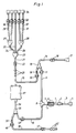
- Fig. 1 is a schematic sideview of a preferred embodiment of the set of tubes according to the invention.
- Fig. 2 is a cross-sectional view of an inlet connector included in the set of tubes.
- Fig. 3 is an endview of the inlet connector according to fig. 2 seen from beneath.
- Fig. 4 is a sideview of a connector piece included in the set of tubes.
- Fig. 5 is a schematical sectional view through a patient tube according to the invention divided into two semicircular halves or channels.
- Fig. 6 is a cross-sectional view similar to Fig. 5 through a preferred embodiment of the patient tube according to the invention divided into four channels.
- Fig. 7 is a cross-sectional view similar to Fig. 5 through an alternative embodiment of the patient tube according to the invention also divided into four channels.
- Fig. 1 shows a preferred embodiment of the set of tubes according to the invention. Concerning how the shown components can be constructed in more detail, reference is made to that which is generally known, for example from the above mentioned patent publications.
- the shown set of tubes consists of a patient tube 1 which, via a connector piece 2, communicates with a patient conduit 3 which, in turn, is connectable with the help of a connector arrangement 4 to a patient's peritoneal catheter.
- the patient tube 1 is divided into two channels by means of common partition wall 5, that is, one channel 6 for fresh dialysis solution and one channel 7 for the spent dialysis solution.
- the patient tube 1 is connected via a T-connector 8 to both a tube 9 for the supply of fresh dialysis solution and to a tube 10 for the discharge of spent dialysis solution.
- the tube 9 can be closed with the help of a clamp arrangement 11 and, in the same way, the tube 10 can be closed with the help of a clamp arrangement 12.
- the tube 9 communicates with two tubes 14 and 15 via a Y-piece 13.
- the tube 14 is provided with a tube clamp 16 and is terminated with a connector arrangement 17 intended to be connected to a bag or similar for control of the weight and/or the volume of supplied dialysis fluid.
- the tube 15 is provided with a coloured, for example green, indication 18 which is intended to simplify the attachment of the complete set of tubes to a dialysis monitor. From the indication, the tube 15 extends through a clamp arrangement 19 and is terminated with a connector arrangement 20 which connects this to a tube 21 which is provided with a tube clamp 22. The tube 21 is terminated with a connector piece 23 which connects this to three tubes 24, 25 and 26. The tubes 24 and 26 are terminated in turn with the help of Y-pieces 27 and 28, which communicate with tubes 29, 30, 31 and 32. All tubes 29, 30, 25, 31 and 32 are provided with tube clamps 33 and are terminated with connector arrangements 34. These connector arrangements 34 are intended to be connected to different sources of fresh dialysis solution, for example five bags containing said solution. Supply can hereby be achieved via the force of gravity by placing the bags at a suitable height, or with the help of suitable pump arrangements. In the shown example, five connector arrangements 34 are shown. In practice any from one to ten can be used.
- the tube 10 is terminated with a Y-piece 35 which connects this to a tube 36 and a bag 37.
- the bag 37 is intended to be used for control of the weight and/or the volume of spent dialysis fluid.
- the bag can for example be placed on scales.
- the tube 10 is, via the Y-piece 35, also connected to a discharged tube 38 which is provided with, for example, a blue colour marking 39, which has the same function as the colour marking 18.
- the tube 38 extends from the colour marking 39 via a clamp arrangement 40 and a tube clamp 41 to a connector arrangement 42 which is intended to connect the tube to a bag or similar intended for collection of waste.
- the T-connector 8 shown in figs. 1-3 can alternatively be formed as, for example, a Y-piece. What is hereby important is only that the inlets 9' and 10' which are intended to be connected to the tubes 9, 10 respectively, are separated from each other via a partition wall 5'. The semi-circular shaped channels 6' and 7' are both separated from each other and communicate with just one of the inlets 9', 10' respectively.
- Figure reference numeral 43 denotes a ring-shaped channel in which the patient tube 1 is intended to be inserted.
- the partition wall 5 is inserted into a slot 44.
- Reference numeral 45 denotes recesses from mould cores which are necessary for the forming of the channels 6' and 7'.
- FIG. 4 there is shown an example of how the connector piece 2 can be formed.
- a section of the patient tube 1 is hereby shown inserted in a cavity 46 which leads into an open chamber 47.
- the two channels 6 and 7 are thus placed in open communication with this chamber 47.
- Via a connection nipple 48 they thereafter communicate with the patient conduit 3 shown in fig. 1.
- Fig 5-7 show sections through three different patient tubes made in accordance with the present invention.
- the three tubes have been given the reference numerals 1a, 1b and 1c, respectively.
- the tube 1a is divided into two channels 6a and 7a by a partition wall 5a.
- the tube 1b is divided into four channels 6b, 6b, 7b and 7b by two perpendicularly arranged partition walls 5b.
- the tube 1c is divided into four channels 6c, 6c, 7c and 7c by a modified arrangement of partition walls 5c.
- the two tubes 1b and 1c have the advantage over the tube 1a in that they are more difficult to bend. Furthermore, the heat transfer between the spent dialysis solution and the fresh solution is improved.
- the invention is not restricted to solely the above described embodiments, but can be varied within the scope of the following claims.
- many components can be modified in accordance with that which is described in the above mentioned patent publications.
- the two channels 6 and 7 can be formed as two concentrically arranged circular shaped channels, i.e. with an inner tube arranged centrally in an outer tube.
- the shown set of tubes can be complemented with further components if so required, for example with a pump unit if it is desired to pump the various liquids.
Landscapes
- Health & Medical Sciences (AREA)
- Emergency Medicine (AREA)
- Urology & Nephrology (AREA)
- Heart & Thoracic Surgery (AREA)
- Vascular Medicine (AREA)
- Engineering & Computer Science (AREA)
- Anesthesiology (AREA)
- Biomedical Technology (AREA)
- Hematology (AREA)
- Life Sciences & Earth Sciences (AREA)
- Animal Behavior & Ethology (AREA)
- General Health & Medical Sciences (AREA)
- Public Health (AREA)
- Veterinary Medicine (AREA)
- External Artificial Organs (AREA)
Applications Claiming Priority (2)
| Application Number | Priority Date | Filing Date | Title |
|---|---|---|---|
| SE9100471 | 1991-02-18 | ||
| SE9100471A SE9100471D0 (sv) | 1991-02-18 | 1991-02-18 | Slangsats avsedd foer peritonealdialys |
Publications (2)
| Publication Number | Publication Date |
|---|---|
| EP0499718A1 EP0499718A1 (en) | 1992-08-26 |
| EP0499718B1 true EP0499718B1 (en) | 1996-05-08 |
Family
ID=20381921
Family Applications (1)
| Application Number | Title | Priority Date | Filing Date |
|---|---|---|---|
| EP91122356A Expired - Lifetime EP0499718B1 (en) | 1991-02-18 | 1991-12-30 | Set of tubes intended for peritoneal dialysis |
Country Status (7)
| Country | Link |
|---|---|
| US (2) | US5338293A (da) |
| EP (1) | EP0499718B1 (da) |
| JP (1) | JP3183549B2 (da) |
| DE (1) | DE69119396T2 (da) |
| DK (1) | DK0499718T3 (da) |
| ES (1) | ES2086473T3 (da) |
| SE (1) | SE9100471D0 (da) |
Cited By (1)
| Publication number | Priority date | Publication date | Assignee | Title |
|---|---|---|---|---|
| US20220387689A1 (en) * | 2016-11-29 | 2022-12-08 | Gambro Lundia Ab | Dialysis fluid connection system and method |
Families Citing this family (86)
| Publication number | Priority date | Publication date | Assignee | Title |
|---|---|---|---|---|
| US5468952A (en) * | 1992-05-15 | 1995-11-21 | Symbol Technologies, Inc. | Miniature high speed scan element mounted on a personal computer interface card |
| USD377685S (en) * | 1995-09-26 | 1997-01-28 | Haemonetics Corp. | Blood withdrawal and separation set |
| JP2872643B2 (ja) | 1996-05-03 | 1999-03-17 | バクスター・インターナショナル・インコーポレイテッド | 腹膜透析システム、腹膜透析液のパッケージングシステムおよびパッケージ形成方法 |
| AU5091198A (en) | 1996-10-22 | 1998-05-15 | Hemocleanse, Inc. | Continuous flow-through peritoneal dialysis (cfpd) method with control of intraperitoneal pressure |
| US6129699A (en) * | 1997-10-31 | 2000-10-10 | Sorenson Development, Inc. | Portable persistaltic pump for peritoneal dialysis |
| US6030359A (en) | 1996-12-11 | 2000-02-29 | Northgate Technologies Inc | Apparatus and method for delivering fluid flow to a surgical site |
| US6458109B1 (en) | 1998-08-07 | 2002-10-01 | Hill-Rom Services, Inc. | Wound treatment apparatus |
| US6245039B1 (en) | 1998-10-05 | 2001-06-12 | Vasca, Inc. | Methods and apparatus for performing flow-through peritoneal dialysis |
| SE9900400L (sv) * | 1999-02-05 | 2000-08-06 | Gambro Ab | Vätskeledningsanordning |
| US6491658B1 (en) * | 1999-06-29 | 2002-12-10 | Jms Co., Ltd. | Automated solution injection-discharge system and automated peritoneal dialysis system |
| US20040215129A1 (en) * | 1999-09-16 | 2004-10-28 | Gambro Ab | Method and cycler for the administration of a peritoneal dialysis fluid |
| US6764462B2 (en) | 2000-11-29 | 2004-07-20 | Hill-Rom Services Inc. | Wound treatment apparatus |
| US6824533B2 (en) | 2000-11-29 | 2004-11-30 | Hill-Rom Services, Inc. | Wound treatment apparatus |
| DE19962314B4 (de) * | 1999-12-23 | 2005-10-13 | Fresenius Medical Care Deutschland Gmbh | Vorrichtung zur Peritonealdialyse |
| DE19962315C2 (de) * | 1999-12-23 | 2003-03-06 | Fresenius Medical Care De Gmbh | Vorrichtung zur Peritonealdialyse |
| US6497676B1 (en) * | 2000-02-10 | 2002-12-24 | Baxter International | Method and apparatus for monitoring and controlling peritoneal dialysis therapy |
| HUP0302301A2 (hu) | 2000-05-22 | 2003-10-28 | Arthur C. Coffey | SIS és vákuumos kötés kombinációja, és az ilyen kötést hasznosító eljárás sebek kezeléséhez |
| US6976973B1 (en) | 2000-10-12 | 2005-12-20 | Baxter International Inc. | Peritoneal dialysis catheters |
| US6685681B2 (en) | 2000-11-29 | 2004-02-03 | Hill-Rom Services, Inc. | Vacuum therapy and cleansing dressing for wounds |
| US6855135B2 (en) | 2000-11-29 | 2005-02-15 | Hill-Rom Services, Inc. | Vacuum therapy and cleansing dressing for wounds |
| SE523860C2 (sv) * | 2001-01-08 | 2004-05-25 | Gambro Lundia Ab | Kopplingsanordning och medicinsk ledningsuppsättning med sådan kopplingsanordning |
| US8323228B2 (en) | 2007-04-12 | 2012-12-04 | Rex Medical L.P. | Dialysis catheter |
| US7077829B2 (en) * | 2001-01-09 | 2006-07-18 | Rex Medical, L.P. | Dialysis catheter |
| US7011645B2 (en) * | 2001-01-09 | 2006-03-14 | Rex Medical, L.P. | Dialysis catheter |
| US6858019B2 (en) | 2001-01-09 | 2005-02-22 | Rex Medical, L.P. | Dialysis catheter and methods of insertion |
| US6889713B2 (en) * | 2001-03-16 | 2005-05-10 | John A. Navis | Peritoneal dialysis catheter |
| US6659134B2 (en) * | 2001-03-16 | 2003-12-09 | John Navis | Peritoneal dialysis catheter |
| CA2462877A1 (en) | 2001-10-11 | 2003-04-17 | Hill-Rom Services, Inc. | Waste container for negative pressure therapy |
| US7241272B2 (en) | 2001-11-13 | 2007-07-10 | Baxter International Inc. | Method and composition for removing uremic toxins in dialysis processes |
| WO2003057070A2 (en) * | 2001-12-26 | 2003-07-17 | Hill-Rom Services Inc. | Vented vacuum bandage and method |
| US7534927B2 (en) | 2001-12-26 | 2009-05-19 | Hill-Rom Services, Inc. | Vacuum bandage packing |
| AU2002359830A1 (en) | 2001-12-26 | 2003-07-24 | Hill-Rom Services, Inc. | Wound vacuum therapy dressing kit |
| AU2002359824A1 (en) | 2002-04-10 | 2003-10-27 | Hill-Rom Services, Inc. | Access openings in vacuum bandage |
| US7115228B2 (en) * | 2002-05-24 | 2006-10-03 | Baxter International Inc. | One-piece tip protector and organizer |
| US6764761B2 (en) | 2002-05-24 | 2004-07-20 | Baxter International Inc. | Membrane material for automated dialysis system |
| US7153286B2 (en) | 2002-05-24 | 2006-12-26 | Baxter International Inc. | Automated dialysis system |
| US20030217957A1 (en) * | 2002-05-24 | 2003-11-27 | Bowman Joseph H. | Heat seal interface for a disposable medical fluid unit |
| US7175606B2 (en) * | 2002-05-24 | 2007-02-13 | Baxter International Inc. | Disposable medical fluid unit having rigid frame |
| US6929751B2 (en) * | 2002-05-24 | 2005-08-16 | Baxter International Inc. | Vented medical fluid tip protector methods |
| US6939111B2 (en) * | 2002-05-24 | 2005-09-06 | Baxter International Inc. | Method and apparatus for controlling medical fluid pressure |
| WO2004009156A2 (en) * | 2002-07-19 | 2004-01-29 | Baxter International Inc. | Systems and methods for peritoneal dialysis |
| ATE505223T1 (de) | 2002-07-19 | 2011-04-15 | Baxter Int | System für die peritonealdialyse |
| US7238164B2 (en) | 2002-07-19 | 2007-07-03 | Baxter International Inc. | Systems, methods and apparatuses for pumping cassette-based therapies |
| AU2003274901A1 (en) * | 2002-07-19 | 2004-02-09 | Baxter Healthcare S.A. | Systems and methods for performing peritoneal dialysis |
| US11273245B2 (en) | 2002-07-19 | 2022-03-15 | Baxter International Inc. | Dialysis system having a vented disposable dialysis fluid carrying member |
| JP2005536275A (ja) | 2002-08-21 | 2005-12-02 | ヒル−ロム サービシズ,インコーポレイテッド | 創傷閉鎖を防止するための創傷用パッキング |
| JP4691503B2 (ja) | 2003-10-28 | 2011-06-01 | バクスター・インターナショナル・インコーポレイテッド | 医療用流体システムのための、改善されたプライミング、一体性および水頭高さの方法および装置 |
| US8803044B2 (en) * | 2003-11-05 | 2014-08-12 | Baxter International Inc. | Dialysis fluid heating systems |
| US8029454B2 (en) | 2003-11-05 | 2011-10-04 | Baxter International Inc. | High convection home hemodialysis/hemofiltration and sorbent system |
| US8226595B2 (en) * | 2006-05-26 | 2012-07-24 | Baxter International Inc. | Automated dialysis system driven by gravity and vacuum |
| US8496809B2 (en) | 2006-06-05 | 2013-07-30 | Baxter International Inc. | Dynamic weight balancing of flow in kidney failure treatment systems |
| US7789850B2 (en) * | 2007-01-22 | 2010-09-07 | Baxter International Inc. | Weight controlled dialysis system with accelerometer |
| US7731689B2 (en) | 2007-02-15 | 2010-06-08 | Baxter International Inc. | Dialysis system having inductive heating |
| WO2008111111A1 (ja) * | 2007-03-09 | 2008-09-18 | Asahi Kasei Kuraray Medical Co., Ltd. | 体液浄化カセットの成形方法 |
| US7809254B2 (en) * | 2007-07-05 | 2010-10-05 | Baxter International Inc. | Dialysis fluid heating using pressure and vacuum |
| US8496609B2 (en) | 2007-07-05 | 2013-07-30 | Baxter International Inc. | Fluid delivery system with spiked cassette |
| US8512553B2 (en) | 2007-07-05 | 2013-08-20 | Baxter International Inc. | Extracorporeal dialysis ready peritoneal dialysis machine |
| US8157761B2 (en) | 2007-07-05 | 2012-04-17 | Baxter International Inc. | Peritoneal dialysis patient connection system |
| US7955295B2 (en) | 2007-07-05 | 2011-06-07 | Baxter International Inc. | Fluid delivery system with autoconnect features |
| US8078333B2 (en) | 2007-07-05 | 2011-12-13 | Baxter International Inc. | Dialysis fluid heating algorithms |
| US8197087B2 (en) | 2007-07-05 | 2012-06-12 | Baxter International Inc. | Peritoneal dialysis patient connection system using ultraviolet light emitting diodes |
| US8764702B2 (en) * | 2007-07-05 | 2014-07-01 | Baxter International Inc. | Dialysis system having dual patient line connection and prime |
| US7736328B2 (en) | 2007-07-05 | 2010-06-15 | Baxter International Inc. | Dialysis system having supply container autoconnection |
| US8262602B2 (en) * | 2008-06-02 | 2012-09-11 | Baxter International Inc. | Remote exchange peritoneal dialysis |
| US9514283B2 (en) | 2008-07-09 | 2016-12-06 | Baxter International Inc. | Dialysis system having inventory management including online dextrose mixing |
| US8062513B2 (en) | 2008-07-09 | 2011-11-22 | Baxter International Inc. | Dialysis system and machine having therapy prescription recall |
| US8057679B2 (en) | 2008-07-09 | 2011-11-15 | Baxter International Inc. | Dialysis system having trending and alert generation |
| US20100051552A1 (en) | 2008-08-28 | 2010-03-04 | Baxter International Inc. | In-line sensors for dialysis applications |
| US9044544B2 (en) * | 2008-11-21 | 2015-06-02 | Baxter International Inc. | Dialysis machine having auto-connection system with roller occluder |
| US11278653B2 (en) | 2009-01-29 | 2022-03-22 | Baxter International Inc. | Method and apparatus for trending automated peritoneal dialysis treatments |
| US8142649B2 (en) * | 2009-01-29 | 2012-03-27 | Baxter International Inc. | Method for optimizing tidal therapies employing ultrafiltrate trending |
| US8182673B2 (en) | 2009-01-29 | 2012-05-22 | Baxter International Inc. | Drain and fill logic for automated peritoneal dialysis |
| US8521482B2 (en) * | 2009-02-20 | 2013-08-27 | Baxter International Inc. | Simulation of patient drain phase in peritoneal dialysis |
| CN105251072B (zh) * | 2009-12-24 | 2017-08-25 | 昆山韦睿医疗科技有限公司 | 一种透析系统 |
| US8591450B2 (en) | 2010-06-07 | 2013-11-26 | Rex Medical L.P. | Dialysis catheter |
| US8936720B2 (en) | 2010-09-17 | 2015-01-20 | Baxter International Inc. | Drain and fill logic for automated peritoneal dialysis |
| US9579443B2 (en) * | 2013-01-10 | 2017-02-28 | Fresenius Medical Care Holdings, Inc. | Peritoneal dialysis systems and related devices and methods |
| US9440017B2 (en) | 2013-03-14 | 2016-09-13 | Baxter International Inc. | System and method for performing alternative and sequential blood and peritoneal dialysis modalities |
| DE102014106490A1 (de) | 2014-05-08 | 2015-11-12 | B. Braun Avitum Ag | Schlauchleitung für frische und/oder verbrauchte Dialysierflüssigkeit |
| EP3314488B1 (en) | 2015-06-25 | 2024-03-13 | Gambro Lundia AB | Medical device system and method having a distributed database |
| KR102476516B1 (ko) | 2016-12-21 | 2022-12-09 | 감브로 룬디아 아베 | 외부 도메인을 지원하는 안전한 클러스터 도메인을 구비한 정보 기술 인프라를 포함하는 의료 장치 시스템 |
| EP3363481B1 (de) * | 2017-02-15 | 2020-05-13 | D.Med Consulting AG | Hämodialyseanordnung |
| US11179516B2 (en) | 2017-06-22 | 2021-11-23 | Baxter International Inc. | Systems and methods for incorporating patient pressure into medical fluid delivery |
| US10814057B2 (en) | 2018-04-05 | 2020-10-27 | Baxter International Inc. | Disposable set for a gravity fed dialysis system |
| EP4011434A1 (en) | 2020-12-10 | 2022-06-15 | Bellco S.r.l. con Unico Socio | Connectors for peritoneal dialysis |
| EP4035706A1 (en) | 2021-01-29 | 2022-08-03 | Bellco S.r.l. | Apparatus for use in peritoneal dialysis |
Family Cites Families (23)
| Publication number | Priority date | Publication date | Assignee | Title |
|---|---|---|---|---|
| US32303A (en) * | 1861-05-14 | Time-telltale | ||
| US1960417A (en) * | 1931-04-01 | 1934-05-29 | Ross Inc Will | Infusion apparatus |
| US3709222A (en) * | 1970-12-28 | 1973-01-09 | Sarns Inc | Method and apparatus for automatic peritoneal dialysis |
| USRE32303E (en) | 1973-07-31 | 1986-12-09 | American Medical Products Corp. | Peritoneal dialysis apparatus |
| DE2535191A1 (de) * | 1975-08-07 | 1977-02-24 | Ulrich Joachim Pfeiffer | Ein endotracheales beatmungssystem mit minimalem totraum |
| DE2703087C2 (de) * | 1977-01-26 | 1984-11-29 | Günter van Dr.med. 4000 Düsseldorf Endert | Doppellumenkatheter |
| US4096859A (en) * | 1977-04-04 | 1978-06-27 | Agarwal Mahesh C | Apparatus for peritoneal dialysis |
| CA1125134A (en) * | 1977-05-16 | 1982-06-08 | Albert F. Bujan | Apparatus for administering incompatible i.v. liquids |
| DE2754809C2 (de) * | 1977-12-09 | 1984-10-11 | Fresenius AG, 6380 Bad Homburg | Vorrichtung zur periodischen Spülung von Körperhöhlen, insbesondere der Bauchhöhle und der Harnblase |
| DE2755214C3 (de) * | 1977-12-10 | 1980-12-11 | Dr. Eduard Fresenius Chemisch-Pharmazeutische Industrie Kg Apparatebau Kg, 6380 Bad Homburg | Vorrichtung zur periodischen Spülung der Bauchhöhle |
| IT1166846B (it) * | 1979-05-25 | 1987-05-06 | Bieffe Spa | Metodo e dispositivo per dialis peritoneale ambulante |
| IT7943514A0 (it) * | 1979-10-26 | 1979-10-26 | Buoncristiani Vincenzo | Apparecchiatura automatica per la dialisi peritoneale col riciclaggiodel liquido dello scarico durante la seduta dialitica |
| US4416280A (en) * | 1980-04-07 | 1983-11-22 | Minnesota Mining And Manufacturing Company | Cardioplegia delivery system |
| US4496349A (en) * | 1981-05-08 | 1985-01-29 | Renal Systems, Inc. | Percutaneous implant |
| SE456637B (sv) * | 1982-04-13 | 1988-10-24 | Gambro Lundia Ab | Vaermesteriliserbar koppling |
| US4560472A (en) * | 1982-12-10 | 1985-12-24 | Baxter Travenol Laboratories, Inc. | Peritoneal dialysis apparatus |
| EP0243547B1 (en) * | 1986-05-01 | 1991-07-24 | Alan M. Peabody | Continuous flow peritoneal dialysis apparatus |
| US4701159A (en) * | 1984-12-05 | 1987-10-20 | I-Flow Corporation | Multilumen catheter set |
| US4687471A (en) * | 1985-05-01 | 1987-08-18 | Curators Of The University Of Missouri | Peritoneal dialysis catheter |
| GB8723931D0 (en) * | 1987-10-12 | 1987-11-18 | Hsc Res Dev Corp | Peritoneal dialysis catheter |
| US4851126A (en) * | 1987-11-25 | 1989-07-25 | Baxter International Inc. | Apparatus and methods for generating platelet concentrate |
| EP0335814B1 (en) * | 1988-01-29 | 1994-11-23 | Paul Anassis | Peritoneal dialysis system |
| US4935004A (en) * | 1988-12-20 | 1990-06-19 | Henry Ford Health System | Peritoneal dialysis catheter |
-
1991
- 1991-02-18 SE SE9100471A patent/SE9100471D0/xx unknown
- 1991-12-30 DE DE69119396T patent/DE69119396T2/de not_active Expired - Fee Related
- 1991-12-30 DK DK91122356.8T patent/DK0499718T3/da active
- 1991-12-30 EP EP91122356A patent/EP0499718B1/en not_active Expired - Lifetime
- 1991-12-30 ES ES91122356T patent/ES2086473T3/es not_active Expired - Lifetime
-
1992
- 1992-02-17 JP JP02953392A patent/JP3183549B2/ja not_active Expired - Lifetime
-
1993
- 1993-05-14 US US08/062,326 patent/US5338293A/en not_active Expired - Lifetime
-
1994
- 1994-02-03 US US08/191,075 patent/US5334139A/en not_active Expired - Lifetime
Cited By (2)
| Publication number | Priority date | Publication date | Assignee | Title |
|---|---|---|---|---|
| US20220387689A1 (en) * | 2016-11-29 | 2022-12-08 | Gambro Lundia Ab | Dialysis fluid connection system and method |
| US12171920B2 (en) * | 2016-11-29 | 2024-12-24 | Gambro Lundia Ab | Dialysis fluid connection system and method |
Also Published As
| Publication number | Publication date |
|---|---|
| DE69119396T2 (de) | 1997-01-23 |
| JPH04319361A (ja) | 1992-11-10 |
| DK0499718T3 (da) | 1996-05-28 |
| DE69119396D1 (de) | 1996-06-13 |
| EP0499718A1 (en) | 1992-08-26 |
| ES2086473T3 (es) | 1996-07-01 |
| US5338293A (en) | 1994-08-16 |
| JP3183549B2 (ja) | 2001-07-09 |
| US5334139A (en) | 1994-08-02 |
| SE9100471D0 (sv) | 1991-02-18 |
Similar Documents
| Publication | Publication Date | Title |
|---|---|---|
| EP0499718B1 (en) | Set of tubes intended for peritoneal dialysis | |
| EP0490459B1 (en) | Multilumen catheter | |
| US5163900A (en) | Disposable cassette systems | |
| TW503097B (en) | Method and apparatus for monitoring and controlling peritoneal dialysis therapy | |
| US7163531B2 (en) | User-friendly catheter connection adapters for optimized connection to multiple lumen catheters | |
| CA2425501A1 (en) | Peritoneal dialysis catheters | |
| CA1270777A (en) | Three-way connector for liquid exchange | |
| US5141499A (en) | Peritoneal dialysis catheter | |
| EP0713406B1 (en) | Triple lumen catheter | |
| US5221256A (en) | Multiple-lumen catheter | |
| US5486159A (en) | Multiple-lumen catheter | |
| US5207648A (en) | Multilumen catheter | |
| EP0568275B1 (en) | Blood air trap chamber | |
| EP0446202A1 (en) | IMPLANTABLE INFUSION APPARATUS. | |
| US20040158190A1 (en) | Support element for an integrated module for blood treatment, an integrated module for blood treatment, and a manufacturing process for an integrated module for blood treatment | |
| CA2278035A1 (en) | Longitudinally aligned dual reservoir access port | |
| CA2307302A1 (en) | Portable peristaltic pump for peritoneal dialysis | |
| US4551130A (en) | Surgical drainage and irrigation apparatus for post operative patient care | |
| JPH059111B2 (da) | ||
| WO1981001793A1 (en) | Blood circuit and bubble traps | |
| CN100493634C (zh) | 支撑元件、集成模块以及装配方法 | |
| JPH04845Y2 (da) | ||
| US7621885B2 (en) | Set of units for a device integrated in an extracorporeal blood circuit | |
| EP1161275A1 (en) | Catheter with improved junction housing | |
| US4581011A (en) | Prepackaged manual administration set for acute peritoneal dialysis in infants and adults |
Legal Events
| Date | Code | Title | Description |
|---|---|---|---|
| PUAI | Public reference made under article 153(3) epc to a published international application that has entered the european phase |
Free format text: ORIGINAL CODE: 0009012 |
|
| AK | Designated contracting states |
Kind code of ref document: A1 Designated state(s): BE CH DE DK ES FR GB IT LI NL SE |
|
| 17P | Request for examination filed |
Effective date: 19930119 |
|
| 17Q | First examination report despatched |
Effective date: 19941219 |
|
| GRAH | Despatch of communication of intention to grant a patent |
Free format text: ORIGINAL CODE: EPIDOS IGRA |
|
| GRAA | (expected) grant |
Free format text: ORIGINAL CODE: 0009210 |
|
| ITF | It: translation for a ep patent filed | ||
| AK | Designated contracting states |
Kind code of ref document: B1 Designated state(s): BE CH DE DK ES FR GB IT LI NL SE |
|
| REG | Reference to a national code |
Ref country code: CH Ref legal event code: NV Representative=s name: A. BRAUN, BRAUN, HERITIER, ESCHMANN AG PATENTANWAE |
|
| REG | Reference to a national code |
Ref country code: DK Ref legal event code: T3 |
|
| REF | Corresponds to: |
Ref document number: 69119396 Country of ref document: DE Date of ref document: 19960613 |
|
| REG | Reference to a national code |
Ref country code: ES Ref legal event code: FG2A Ref document number: 2086473 Country of ref document: ES Kind code of ref document: T3 |
|
| ET | Fr: translation filed | ||
| PLBE | No opposition filed within time limit |
Free format text: ORIGINAL CODE: 0009261 |
|
| STAA | Information on the status of an ep patent application or granted ep patent |
Free format text: STATUS: NO OPPOSITION FILED WITHIN TIME LIMIT |
|
| 26N | No opposition filed | ||
| REG | Reference to a national code |
Ref country code: GB Ref legal event code: IF02 |
|
| PGFP | Annual fee paid to national office [announced via postgrant information from national office to epo] |
Ref country code: NL Payment date: 20021031 Year of fee payment: 12 |
|
| PGFP | Annual fee paid to national office [announced via postgrant information from national office to epo] |
Ref country code: SE Payment date: 20021119 Year of fee payment: 12 |
|
| PGFP | Annual fee paid to national office [announced via postgrant information from national office to epo] |
Ref country code: DK Payment date: 20021122 Year of fee payment: 12 |
|
| PGFP | Annual fee paid to national office [announced via postgrant information from national office to epo] |
Ref country code: CH Payment date: 20021218 Year of fee payment: 12 |
|
| PGFP | Annual fee paid to national office [announced via postgrant information from national office to epo] |
Ref country code: BE Payment date: 20030107 Year of fee payment: 12 |
|
| PG25 | Lapsed in a contracting state [announced via postgrant information from national office to epo] |
Ref country code: BE Free format text: LAPSE BECAUSE OF NON-PAYMENT OF DUE FEES Effective date: 20031231 Ref country code: SE Free format text: LAPSE BECAUSE OF NON-PAYMENT OF DUE FEES Effective date: 20031231 Ref country code: LI Free format text: LAPSE BECAUSE OF NON-PAYMENT OF DUE FEES Effective date: 20031231 Ref country code: CH Free format text: LAPSE BECAUSE OF NON-PAYMENT OF DUE FEES Effective date: 20031231 |
|
| PG25 | Lapsed in a contracting state [announced via postgrant information from national office to epo] |
Ref country code: DK Free format text: LAPSE BECAUSE OF NON-PAYMENT OF DUE FEES Effective date: 20040102 |
|
| REG | Reference to a national code |
Ref country code: CH Ref legal event code: PFA Owner name: GAMBRO LUNDIA AB Free format text: GAMBRO AB#POST BOX 10101#S-220 10 LUND (SE) -TRANSFER TO- GAMBRO LUNDIA AB#BOX 10101#220 10 LUND (SE) |
|
| REG | Reference to a national code |
Ref country code: ES Ref legal event code: PC2A |
|
| BERE | Be: lapsed |
Owner name: *GAMBRO LUNDIA A.B. Effective date: 20031231 |
|
| PG25 | Lapsed in a contracting state [announced via postgrant information from national office to epo] |
Ref country code: NL Free format text: LAPSE BECAUSE OF NON-PAYMENT OF DUE FEES Effective date: 20040701 |
|
| REG | Reference to a national code |
Ref country code: FR Ref legal event code: CD |
|
| EUG | Se: european patent has lapsed | ||
| REG | Reference to a national code |
Ref country code: DK Ref legal event code: EBP |
|
| REG | Reference to a national code |
Ref country code: CH Ref legal event code: PL |
|
| NLV4 | Nl: lapsed or anulled due to non-payment of the annual fee |
Effective date: 20040701 |
|
| PGFP | Annual fee paid to national office [announced via postgrant information from national office to epo] |
Ref country code: GB Payment date: 20051104 Year of fee payment: 15 |
|
| PGFP | Annual fee paid to national office [announced via postgrant information from national office to epo] |
Ref country code: FR Payment date: 20051201 Year of fee payment: 15 |
|
| PGFP | Annual fee paid to national office [announced via postgrant information from national office to epo] |
Ref country code: DE Payment date: 20051230 Year of fee payment: 15 |
|
| PG25 | Lapsed in a contracting state [announced via postgrant information from national office to epo] |
Ref country code: DE Free format text: LAPSE BECAUSE OF NON-PAYMENT OF DUE FEES Effective date: 20070703 |
|
| GBPC | Gb: european patent ceased through non-payment of renewal fee |
Effective date: 20061230 |
|
| REG | Reference to a national code |
Ref country code: FR Ref legal event code: ST Effective date: 20070831 |
|
| PG25 | Lapsed in a contracting state [announced via postgrant information from national office to epo] |
Ref country code: GB Free format text: LAPSE BECAUSE OF NON-PAYMENT OF DUE FEES Effective date: 20061230 |
|
| PGFP | Annual fee paid to national office [announced via postgrant information from national office to epo] |
Ref country code: ES Payment date: 20071217 Year of fee payment: 17 |
|
| PGFP | Annual fee paid to national office [announced via postgrant information from national office to epo] |
Ref country code: IT Payment date: 20071215 Year of fee payment: 17 |
|
| PG25 | Lapsed in a contracting state [announced via postgrant information from national office to epo] |
Ref country code: FR Free format text: LAPSE BECAUSE OF NON-PAYMENT OF DUE FEES Effective date: 20070102 |
|
| REG | Reference to a national code |
Ref country code: ES Ref legal event code: FD2A Effective date: 20081231 |
|
| PG25 | Lapsed in a contracting state [announced via postgrant information from national office to epo] |
Ref country code: ES Free format text: LAPSE BECAUSE OF NON-PAYMENT OF DUE FEES Effective date: 20081231 |
|
| PG25 | Lapsed in a contracting state [announced via postgrant information from national office to epo] |
Ref country code: IT Free format text: LAPSE BECAUSE OF NON-PAYMENT OF DUE FEES Effective date: 20081230 |