EP0499730B1 - Funktionsüberwachungssystem und Verfahren eines Funkempfängers - Google Patents
Funktionsüberwachungssystem und Verfahren eines Funkempfängers Download PDFInfo
- Publication number
- EP0499730B1 EP0499730B1 EP91301461A EP91301461A EP0499730B1 EP 0499730 B1 EP0499730 B1 EP 0499730B1 EP 91301461 A EP91301461 A EP 91301461A EP 91301461 A EP91301461 A EP 91301461A EP 0499730 B1 EP0499730 B1 EP 0499730B1
- Authority
- EP
- European Patent Office
- Prior art keywords
- radio
- receivers
- squelch
- radio receiver
- receiver
- Prior art date
- Legal status (The legal status is an assumption and is not a legal conclusion. Google has not performed a legal analysis and makes no representation as to the accuracy of the status listed.)
- Expired - Lifetime
Links
- 238000000034 method Methods 0.000 title claims description 8
- 230000003252 repetitive effect Effects 0.000 claims abstract description 15
- 230000005236 sound signal Effects 0.000 claims description 4
- 230000000694 effects Effects 0.000 claims 2
- 230000000737 periodic effect Effects 0.000 abstract description 2
- 230000000007 visual effect Effects 0.000 abstract description 2
- 238000004891 communication Methods 0.000 description 8
- 230000007704 transition Effects 0.000 description 3
- 230000030279 gene silencing Effects 0.000 description 2
- 238000012986 modification Methods 0.000 description 2
- 230000004048 modification Effects 0.000 description 2
- 230000001960 triggered effect Effects 0.000 description 2
- 230000005540 biological transmission Effects 0.000 description 1
- 230000001419 dependent effect Effects 0.000 description 1
- 238000010586 diagram Methods 0.000 description 1
- 230000009977 dual effect Effects 0.000 description 1
- 238000012544 monitoring process Methods 0.000 description 1
- 238000004806 packaging method and process Methods 0.000 description 1
- 238000005070 sampling Methods 0.000 description 1
- 238000004092 self-diagnosis Methods 0.000 description 1
Images

Classifications
-
- H—ELECTRICITY
- H04—ELECTRIC COMMUNICATION TECHNIQUE
- H04B—TRANSMISSION
- H04B1/00—Details of transmission systems, not covered by a single one of groups H04B3/00 - H04B13/00; Details of transmission systems not characterised by the medium used for transmission
- H04B1/06—Receivers
- H04B1/16—Circuits
-
- H—ELECTRICITY
- H04—ELECTRIC COMMUNICATION TECHNIQUE
- H04B—TRANSMISSION
- H04B1/00—Details of transmission systems, not covered by a single one of groups H04B3/00 - H04B13/00; Details of transmission systems not characterised by the medium used for transmission
- H04B1/06—Receivers
- H04B1/10—Means associated with receiver for limiting or suppressing noise or interference
Definitions
- This invention relates to a radio receiver operational checking system using the radio receiver's active signal squelch circuit to measure the operability of a radio receiver including identifying which receiver is being checked where a plurality of radio receivers are being monitored.
- squelch circuitry known as "squelch” to make the receiver silent until a "threshold” signal strength is reached, at which time full listening power is activated.
- Receivers with squelch have a knob for the operator to adjust to the critical silencing point, or "threshold.” In some receivers, the adjustment is preset and a pull-knob disables squelch entirely, giving full background noise when volume is turned up. Without the squelch circuitry, there is a continual noise in the form of loud hissing or crackling, commonly known as background noise. The noise is distracting and unpleasant; hence, the use of squelch circuitry systems.
- Some pilots and communicators disable squelch and tolerate the noise in order to know that the radio is live. Others leave the squelch control on and trust blindly to fate. Still others bungle and foul up their communication by inadvertently having the radio turned down or off.
- U.S. Patent No. 4,718,115 entitled “RADIO RECEIVER FOR CARRYING OUT SELF DIAGNOSIS WITHOUT INTERFERENCE,” is of interest as a general reference in this case as it discloses the category of prior art where a separate diagnostic signal is introduced in the path of the incoming signal as it goes through the radio receiver.
- This category of prior art is distinctively different from the present invention in that the invention, which is to be described herein, periodically deactivates the squelch circuitry as a method of determining the operational status of the radio and does not use a separate diagnostic signal.
- subliminal or near-subliminal refers to pulse duration which is long enough to be heard without being intrusive or annoying.
- This invention solves the problem of determining the operational status of squelch-silenced radios, and further adds the option of having an effectively silent radio when no voice is present, by providing near-subliminal short bursts of full-sensitivity receiver noise to indicate that the radio is operational and that the volume is adequately adjusted. In addition, if more than one radio is being used, the system indicates which of the radios are properly live.
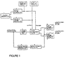
- FIGURE 1 is a block diagram of the circuitry of the invention.
- FIGURES 2A-L show the wave-form/pulse timing of the signals generated using the invention.
- the clock generator (Block 1) creates a rectangular symmetrical wave-form of approximately two seconds between transitions (FIG. 2A).
- Radio 1 pulse generator (Block 2) is triggered when the transition goes from high to low, and generates a ten millisecond pulse (FIG. 2B) which is sent to deactivate momentarily the Radio 1 squelch circuit.
- Subsequent clock pulse transition from low to high triggers the radio 2 pulse generator (Block 3).
- the output pulse pair (FIG. 2D) is likewise wired to the squelch circuit of Radio 2 to deactivate momentarily the squelch and pass the bursts of noise.
- These pulses are grouped to identify which radio is being checked; thus, double pulse is Radio 2 and single pulse is Radio 1.
- the equipment as described above is adequate to perform the audible communication checking claimed in this invention, since the pilot or communicator can hear the periodic noise burst from the "de-squelch" pulses. Note that the squelch system of the radio keeps the radio silent when there is no signal.
- Blocks 4, 5, 6, 7 provide visual indication to show which radio or radios are live.
- a Light-Emitting Diode (LED) connected to each radio shows when a particular radio is turned on and adjusted for audible reception.
- LED Light-Emitting Diode
- a noise burst amplifier (Block 4) "listens" on the headphone audio line for any sound. This line would be squelched silent with zero audio signal when no voice transmission was being received -- if it were not for the pulsed noise bursts.
- Block 4 amplifies these noise bursts when heard at headphone level.
- the pulse if present, is amplified and shaped in Block 4 and is passed to a NAND gate (Block 5). This gate passes the pulse on to Block 6 (Radio 1 LED light pulse stretch) if the noise burst pulse occurs co-incident with Radio 1 pulses. Similarly, if headphone noise pulses are co-incident with Radio 2 gating pulses, they are sent to Block 7 (LED pulse stretch for Radio 2).
- Blocks 6 and 7 LED pulse stretchs
- Blocks 6 and 7 when triggered from the gate, turn on the LEDs for most of the four second period between similar pulses. This gives nearly continuous light indication to show which radio is live.
- the short period during which the indicator blinks dark in each period is a self-checking feature which shows that the light is dependent on the audio noise pulse and is therefore a valid indicator.
- Blocks 8 and 9 disable both indicator lights when voice communication is being received. This is shown in FIGS. 2K and 2L. Voice reception would confuse the indication because voice audio signal is present at the sampling instants for the noise pulse checking. This circuit solves the trouble of both lights coming on erratically when voice is present by preventing either light from turning on when voice is present.
- a logarithmic response is used to accomodate wide variations in audio level at the headphone line.
- Blocks 1-3, 5 and 6 in FIGURE 1 are made up of integrated circuit (IC) chips of the "TIMER" classification, which are standard eight (8) pin chips. For compact packaging, dual or multiple units can be used. The economical type 555 or 556 have been used.
- Block 4 can be a 741 Op Amp IC and Block 5 a 7400 Quadrangle NAND Gate IC.
- Block 8 is an Op Amp IC such as a type 741;
- Block 9 is a Timer IC such as a type 555.
Landscapes
- Engineering & Computer Science (AREA)
- Computer Networks & Wireless Communication (AREA)
- Signal Processing (AREA)
- Burglar Alarm Systems (AREA)
- Alarm Systems (AREA)
- Monitoring And Testing Of Transmission In General (AREA)
- Circuits Of Receivers In General (AREA)
- Noise Elimination (AREA)
Claims (12)
- Funktionsüberwachungssystem für Funkempfänger mit folgenden Kombinationsmerkmalen:a) einem Funkempfänger mit einer aktiven Sperrschaltung für Funkrauschen, die auf einen Pegel eingestellt ist, um bei Nichtempfang eines Funksignals Umgebungsrauschen, d.h. atmosphärisches und empfängereigenes Rauschen, auszuschalten, und einen Sperrschaltungs-Steuerverbindungspunkt aufweist, womit die Sperrschaltung durch Anlegen einer Spannung geeigneter Größe außer Funktion gesetzt werden kann,b) einer taktgesteuerten Impulsquelle (2; 3) für den Funkempfänger, die sich wiederholende kurze Impulse zur Beaufschlagung des Sperrschaltungs-Steuerverbindungspunktes liefert, um die Sperrschaltung in regelmäßigen Zeitabständen augenblicklich zu deaktivieren und so sich wiederholende kurze Störsignalimpulse an dem Audioausgang des Funkempängers auftreten läßt, die anzeigen, daß der Funkempfänger funktionsfähig ist und ein Funkfrequenzsignal erwartet.
- Funktionsüberwachungssystem für Funkempfänger nach Anspruch 1, des weiteren enthaltend Lichtanzeigemittel für den Funkempfänger zum visuellen Anzeigen der kurzen Audiorausch-Ausgangsimpulse des Empfängers, die sich einschalten, wenn das aus den kurzen Rauschimpulsen bestehende Ausgangssignal des Empfängers mit den dem Sperrschaltungs-Steuerverbindungspunkt des Funkempfängers zugeführten kurzen Impulsen aus der taktgesteuerten Impulsquelle (2; 3) zusammenfallen, als Anzeige für die Funktionsfähigkeit des Empfängers.
- Funktionsüberwachungssystem für Funkempfänger nach Anspruch 1, worin eine Mehrzahl Funkempfänger und eine taktgesteuerte Impulsquelle (2; 3) für unterschiedliche Impulse für jeden der Funkempfänger auftritt.
- Funktionsüberwachungssystem für Funkempfänger nach Anspruch 3, worin die verschiedenen taktgesteuerten Impulsquellen (2, 3) sich nach Zeitabstand und Wellenform unterscheiden, so daß die Audio-Ausgangssignale der einzelnen Funkempfänger hörbar voneinander zu unterscheiden sind.
- Funktionsüberwachungssystem für Funkempfänger nach Anspruch 4, des weiteren enthaltend Lichtanzeigemittel für einen jeden der Funkempfänger zum visuellen Anzeigen der kurzen Audiorausch-Ausgangsimpulse der Empfänger, die sich einschalten, wenn das aus den kurzen Rauschimpulsen bestehende Ausgangssignal der Empfänger mit den auf die Sperrschaltungs-Steuerverbindungspunkte der Funkempfänger gegebenen kurzen Impulsen aus den taktgesteuerten Impulsquellen (2, 3) zusammenfallen, als Anzeige für die Funktionsfähigkeit der Empfänger.
- Funktionsüberwachungssystem für Funkempfänger nach Anspruch 5, des weiteren enthaltend auf Audiosignale ansprechende Mittel (8) zum Ausschalten der Lichtanzeigemittel (6; 7) für einen jeden der Empfänger, wenn ein jeder der Empfänger ein Funksignal empfängt.
- Verfahren zum Überwachen der Funktionsfähigkeit zumindest eines eine Rauschsperrschaltung aufweisenden Funkempfängers mit folgenden Verfahrensschritten:a) Anlegen sich wiederholender kurzer Impulse an den Sperrschaltungs-Steuerverbindungspunkt des Funkempfängers zum Deaktivieren der Sperrschaltung in regelmäßigen Zeitabständen, um am Audioausgang des Funkempfängers sich wiederholende kurze Rauschsignalimpulse auftreten zu lassen, die anzeigen, daß der Funkempfänger funktionsfähig ist und ein Funkfrequenzsignal erwartet,b) die an den Sperrschaltungs-Steuerverbindungspunkt gelieferten, sich wiederholenden kurzen Impulse sind genügend kurzzeitig, um einen vernachlässigbaren Einfluß auf den Piloten oder Funker zu haben.
- Verfahren nach Anspruch 7, worin die sich wiederholenden kurzen Impulse hinreichend kurzzeitig und von hinreichend kleiner Amplitude sind, um von dem Piloten oder Funker beinahe unterbewußt wahrgenommen zu werden.
- Verfahren nach Anspruch 7, des weiteren enthaltend den zusätzlichen Schritt, die an den Sperrschaltungs-Steuerverbindungspunkt des Funkempfängers zur Deaktivierung der Sperrschaltung in regelmäßigen Zeitabständen gelieferten, sich wiederholenden kurzen Impulse auch auf Lichtanzeigemittel (6; 7) zu geben zur Anzeige dessen, daß der Funkempfänger funktionsfähig ist und ein Funkfrequenzsignal erwartet.
- Verfahren zur Überwachung der Funktionsfähigkeit einer Mehrzahl von Funkempfängern, deren jeder eine Rauschsperrschaltung aufweist, mit folgenden Verfahrensschritten:a) Anlegen sich wiederholender kurzer Impulse aus separaten, koordinierten Impulsquellen (2, 3) an den Sperrschaltungs-Steuerverbindungspunkt eines jeden der Funkempfänger zum Deaktivieren der Sperrschaltungen in regelmäßigen Zeitabständen, um am Audioausgang der Funkempänger sich wiederholende kurze, identifizierbare Rauschsignalimpulse auftreten zu lassen, die anzeigen, welche der Funkempfänger funktionsfähig sind und ein Funkfrequenzsignal erwarten,b) Beabstanden der sich wiederholenden kurzen Impulse aus einer jeden der koordinierten Impulsquellen für einen jeden der Empfänger nach Zeit und Wellenform derart, daß die hörbaren Ausgangssignale der einzelnen Funkempfänger hörbar voneinander zu unterscheiden sind,c) die auf die Sperrschaltungs-Steuerverbindungspunkte gegebenen, sich wiederholenden kurzen Impulse sind von hinreichend kurzer Dauer, um bei ihrem Auftreten einen vernachlässigbaren Einfluß auf den Piloten oder Funker zu haben.
- Verfahren nach Anspruch 10, des weiteren enthaltend den zusätzlichen Schritt, die sich wiederholenden kurzen Impulse auch auf Lichtanzeigemittel (6, 7) zu geben zur Anzeige dessen, daß die Funkempfänger funktionsfähig sind und Funkfrequenzsignale erwarten, wobei die Lichtanzeigemittel (6; 7) normalerweise ausgeschaltet, jedoch auf die sich wiederholenden kurzen Impulse hin eingeschaltet sind.
- Verfahren nach Anspruch 11, des weiteren enthaltend den zusätzlichen Schritt, auf Audiosignale ansprechende Mittel zum Abschalten der Lichtanzeigemittel (6; 7) für einen jeden Empfänger vorzusehen, wenn einer der Empfänger ein Sprechfunksignal empfängt.
Priority Applications (3)
| Application Number | Priority Date | Filing Date | Title |
|---|---|---|---|
| EP91301461A EP0499730B1 (de) | 1991-02-22 | 1991-02-22 | Funktionsüberwachungssystem und Verfahren eines Funkempfängers |
| AT91301461T ATE130985T1 (de) | 1991-02-22 | 1991-02-22 | Funktionsüberwachungssystem und verfahren eines funkempfängers. |
| DE69115018T DE69115018T2 (de) | 1991-02-22 | 1991-02-22 | Funktionsüberwachungssystem und Verfahren eines Funkempfängers. |
Applications Claiming Priority (1)
| Application Number | Priority Date | Filing Date | Title |
|---|---|---|---|
| EP91301461A EP0499730B1 (de) | 1991-02-22 | 1991-02-22 | Funktionsüberwachungssystem und Verfahren eines Funkempfängers |
Publications (2)
| Publication Number | Publication Date |
|---|---|
| EP0499730A1 EP0499730A1 (de) | 1992-08-26 |
| EP0499730B1 true EP0499730B1 (de) | 1995-11-29 |
Family
ID=8208199
Family Applications (1)
| Application Number | Title | Priority Date | Filing Date |
|---|---|---|---|
| EP91301461A Expired - Lifetime EP0499730B1 (de) | 1991-02-22 | 1991-02-22 | Funktionsüberwachungssystem und Verfahren eines Funkempfängers |
Country Status (3)
| Country | Link |
|---|---|
| EP (1) | EP0499730B1 (de) |
| AT (1) | ATE130985T1 (de) |
| DE (1) | DE69115018T2 (de) |
Families Citing this family (1)
| Publication number | Priority date | Publication date | Assignee | Title |
|---|---|---|---|---|
| FI97182C (fi) * | 1994-12-05 | 1996-10-25 | Nokia Telecommunications Oy | Menetelmä vastaanotettujen huonojen puhekehysten korvaamiseksi digitaalisessa vastaanottimessa sekä digitaalisen tietoliikennejärjestelmän vastaanotin |
Family Cites Families (3)
| Publication number | Priority date | Publication date | Assignee | Title |
|---|---|---|---|---|
| US3832636A (en) * | 1972-11-02 | 1974-08-27 | Tokyo Shibaura Electric Co | Transceiver with time division means for indicating the presence of an emergency channel signal while receiving information on a normal channel |
| DE3138650A1 (de) * | 1981-09-29 | 1983-04-14 | TE KA DE Felten & Guilleaume Fernmeldeanlagen GmbH, 8500 Nürnberg | Verfahren zur ueberwachung einer funkempfangsanlage |
| JPS6235727A (ja) * | 1985-08-09 | 1987-02-16 | Nec Corp | 自己診断機能を有する受信機 |
-
1991
- 1991-02-22 DE DE69115018T patent/DE69115018T2/de not_active Expired - Fee Related
- 1991-02-22 AT AT91301461T patent/ATE130985T1/de not_active IP Right Cessation
- 1991-02-22 EP EP91301461A patent/EP0499730B1/de not_active Expired - Lifetime
Also Published As
| Publication number | Publication date |
|---|---|
| DE69115018D1 (de) | 1996-01-11 |
| EP0499730A1 (de) | 1992-08-26 |
| ATE130985T1 (de) | 1995-12-15 |
| DE69115018T2 (de) | 1996-07-25 |
Similar Documents
| Publication | Publication Date | Title |
|---|---|---|
| DE3873600T2 (de) | Schallwellendetektor zum aufrufen von kopfhoererbenutzern. | |
| US4060701A (en) | Method for testing acoustical attenuation of hearing protectors | |
| US3656158A (en) | Integrated fully supervised fire alarm system | |
| WO1997018648A1 (en) | Wireless sound monitoring apparatus with subaudible squelch control | |
| US4996717A (en) | Radio receiver noise squelching and operational indicating alarm | |
| KR900701106A (ko) | 가청 신호처리 시스템을 검사하기 위한 장치 | |
| JPH04286173A (ja) | 光送信装置用レーザーダイオード保護回路 | |
| US4020298A (en) | Apparatus for testing acoustical attenuation of hearing protectors | |
| US4805231A (en) | Apparatus for detecting an electronic surveillance device | |
| EP0499730A1 (de) | Funktionsüberwachungssystem und Verfahren eines Funkempfängers | |
| CA2036788C (en) | Radio receiver operational checking method and system | |
| US5241698A (en) | Radio receiver operational checking method and system including reactive coupling | |
| GB919172A (de) | ||
| GB1578374A (en) | Noise reduction in audio reproducing systems | |
| JPH04278728A (ja) | 無線受信器の検定方法および装置 | |
| US3573780A (en) | Automatic telephone alarm system | |
| US4143323A (en) | Radio receiver monitoring and testing apparatus | |
| KR0145135B1 (ko) | 배전 선로 고장 원격 감시 방법 및 장치 | |
| Wilkins et al. | The role of acoustical characteristics in the perception of warning sounds and the effects of wearing hearing protection | |
| US4021739A (en) | Distress signal protection system | |
| JP2570804B2 (ja) | デブロッキング回路 | |
| DE3624099A1 (de) | Einrichtung zur akustischen warnung von personen ueber einen hochfrequenten nachrichtenkanal | |
| JPH05225458A (ja) | 防災設備の端末のリモコン操作方法及び装置 | |
| SU1168996A1 (ru) | Многоканальное устройство сигнализации | |
| SU1267317A1 (ru) | Устройство автоматического контрол работоспособности сейсмометрических каналов |
Legal Events
| Date | Code | Title | Description |
|---|---|---|---|
| PUAI | Public reference made under article 153(3) epc to a published international application that has entered the european phase |
Free format text: ORIGINAL CODE: 0009012 |
|
| AK | Designated contracting states |
Kind code of ref document: A1 Designated state(s): AT BE CH DE DK ES FR GB GR IT LI LU NL SE |
|
| 17P | Request for examination filed |
Effective date: 19930119 |
|
| 17Q | First examination report despatched |
Effective date: 19950202 |
|
| GRAA | (expected) grant |
Free format text: ORIGINAL CODE: 0009210 |
|
| AK | Designated contracting states |
Kind code of ref document: B1 Designated state(s): AT BE CH DE DK ES FR GB GR IT LI LU NL SE |
|
| PG25 | Lapsed in a contracting state [announced via postgrant information from national office to epo] |
Ref country code: IT Free format text: LAPSE BECAUSE OF FAILURE TO SUBMIT A TRANSLATION OF THE DESCRIPTION OR TO PAY THE FEE WITHIN THE PRE;WARNING: LAPSES OF ITALIAN PATENTS WITH EFFECTIVE DATE BEFORE 2007 MAY HAVE OCCURRED AT ANY TIME BEFORE 2007. THE CORRECT EFFECTIVE DATE MAY BE DIFFERENT FROM THE ONE RECORDED.SCRIBED TIME-LIMIT Effective date: 19951129 Ref country code: BE Effective date: 19951129 Ref country code: AT Effective date: 19951129 Ref country code: LI Effective date: 19951129 Ref country code: CH Effective date: 19951129 Ref country code: DK Effective date: 19951129 Ref country code: NL Free format text: LAPSE BECAUSE OF FAILURE TO SUBMIT A TRANSLATION OF THE DESCRIPTION OR TO PAY THE FEE WITHIN THE PRESCRIBED TIME-LIMIT Effective date: 19951129 Ref country code: GR Free format text: LAPSE BECAUSE OF FAILURE TO SUBMIT A TRANSLATION OF THE DESCRIPTION OR TO PAY THE FEE WITHIN THE PRESCRIBED TIME-LIMIT Effective date: 19951129 Ref country code: ES Free format text: THE PATENT HAS BEEN ANNULLED BY A DECISION OF A NATIONAL AUTHORITY Effective date: 19951129 |
|
| REF | Corresponds to: |
Ref document number: 130985 Country of ref document: AT Date of ref document: 19951215 Kind code of ref document: T |
|
| REF | Corresponds to: |
Ref document number: 69115018 Country of ref document: DE Date of ref document: 19960111 |
|
| PG25 | Lapsed in a contracting state [announced via postgrant information from national office to epo] |
Ref country code: SE Effective date: 19960229 Ref country code: LU Free format text: LAPSE BECAUSE OF NON-PAYMENT OF DUE FEES Effective date: 19960229 |
|
| ET | Fr: translation filed | ||
| NLV1 | Nl: lapsed or annulled due to failure to fulfill the requirements of art. 29p and 29m of the patents act | ||
| REG | Reference to a national code |
Ref country code: CH Ref legal event code: PL |
|
| PLBE | No opposition filed within time limit |
Free format text: ORIGINAL CODE: 0009261 |
|
| STAA | Information on the status of an ep patent application or granted ep patent |
Free format text: STATUS: NO OPPOSITION FILED WITHIN TIME LIMIT |
|
| 26N | No opposition filed | ||
| REG | Reference to a national code |
Ref country code: GB Ref legal event code: IF02 |
|
| PGFP | Annual fee paid to national office [announced via postgrant information from national office to epo] |
Ref country code: GB Payment date: 20040220 Year of fee payment: 14 |
|
| PGFP | Annual fee paid to national office [announced via postgrant information from national office to epo] |
Ref country code: FR Payment date: 20040227 Year of fee payment: 14 |
|
| PGFP | Annual fee paid to national office [announced via postgrant information from national office to epo] |
Ref country code: DE Payment date: 20040325 Year of fee payment: 14 |
|
| PG25 | Lapsed in a contracting state [announced via postgrant information from national office to epo] |
Ref country code: GB Free format text: LAPSE BECAUSE OF NON-PAYMENT OF DUE FEES Effective date: 20050222 |
|
| PG25 | Lapsed in a contracting state [announced via postgrant information from national office to epo] |
Ref country code: DE Free format text: LAPSE BECAUSE OF NON-PAYMENT OF DUE FEES Effective date: 20050901 |
|
| GBPC | Gb: european patent ceased through non-payment of renewal fee |
Effective date: 20050221 |
|
| PG25 | Lapsed in a contracting state [announced via postgrant information from national office to epo] |
Ref country code: FR Free format text: LAPSE BECAUSE OF NON-PAYMENT OF DUE FEES Effective date: 20051031 |
|
| REG | Reference to a national code |
Ref country code: FR Ref legal event code: ST Effective date: 20051031 |