EP0499740B1 - Verriegelungseinrichtung - Google Patents
Verriegelungseinrichtung Download PDFInfo
- Publication number
- EP0499740B1 EP0499740B1 EP91309435A EP91309435A EP0499740B1 EP 0499740 B1 EP0499740 B1 EP 0499740B1 EP 91309435 A EP91309435 A EP 91309435A EP 91309435 A EP91309435 A EP 91309435A EP 0499740 B1 EP0499740 B1 EP 0499740B1
- Authority
- EP
- European Patent Office
- Prior art keywords
- locking
- locking device
- detent
- handle
- key
- Prior art date
- Legal status (The legal status is an assumption and is not a legal conclusion. Google has not performed a legal analysis and makes no representation as to the accuracy of the status listed.)
- Expired - Lifetime
Links
- 230000000994 depressogenic effect Effects 0.000 claims abstract description 12
- 230000003993 interaction Effects 0.000 claims abstract description 4
- 238000000465 moulding Methods 0.000 claims description 2
- 229920003023 plastic Polymers 0.000 claims description 2
- 239000004033 plastic Substances 0.000 claims description 2
- 238000004519 manufacturing process Methods 0.000 abstract description 7
- 239000002184 metal Substances 0.000 description 2
- 230000006835 compression Effects 0.000 description 1
- 238000007906 compression Methods 0.000 description 1
- 239000000463 material Substances 0.000 description 1
- 238000010137 moulding (plastic) Methods 0.000 description 1
Images
Classifications
-
- E—FIXED CONSTRUCTIONS
- E05—LOCKS; KEYS; WINDOW OR DOOR FITTINGS; SAFES
- E05B—LOCKS; ACCESSORIES THEREFOR; HANDCUFFS
- E05B35/00—Locks for use with special keys or a plurality of keys ; keys therefor
- E05B35/008—Locks for use with special keys or a plurality of keys ; keys therefor for simple tool-like keys
-
- E—FIXED CONSTRUCTIONS
- E05—LOCKS; KEYS; WINDOW OR DOOR FITTINGS; SAFES
- E05B—LOCKS; ACCESSORIES THEREFOR; HANDCUFFS
- E05B13/00—Devices preventing the key or the handle or both from being used
- E05B13/10—Devices preventing the key or the handle or both from being used formed by a lock arranged in the handle
-
- E—FIXED CONSTRUCTIONS
- E05—LOCKS; KEYS; WINDOW OR DOOR FITTINGS; SAFES
- E05C—BOLTS OR FASTENING DEVICES FOR WINGS, SPECIALLY FOR DOORS OR WINDOWS
- E05C19/00—Other devices specially designed for securing wings, e.g. with suction cups
- E05C19/06—Other devices specially designed for securing wings, e.g. with suction cups in which the securing part if formed or carried by a spring and moves only by distortion of the spring, e.g. snaps
Definitions
- This invention relates to locking devices, and in particular to a locking device which, during use, is pressed into a locking position and can be released therefrom by means of a key.
- a locking device which, during use, is pressed into a locking position and can be released therefrom by means of a key.
- Such a device is particularly suitable for use in a vent handle locking mechanism.
- Vents such as windows
- a latch which is swung into position by means of a handle rotatably mounted on the vent itself.
- the handle and latch rotate about a pivot secured to the vent, and the latch engages in a recess in, or simply abuts against, the frame of the vent which is solidly mounted in a wall or the like.
- a number of ways of achieving locking of the handle are known.
- the present invention aims to overcome the problems associated with the known prior art handle locking devices.
- a locking device according to the present invention is cheap to manufacture, requires very few parts and can be activated without the use of a key.
- a locking device adapted to be pressed, during use, into a locking position and released therefrom by means of a key, comprising a body portion, having an aperture therein for receiving a key during unlocking, an active portion for effecting locking when the device is depressed and a detent retaining the device in its locking position when depressed, characterised in that the detent is attached to the body portion by means of a resilient web, and in that interaction of the key with the locking device bends the resilient web, thereby de-activating the detent and enabling the device to be biased back into its unlocked position.
- the locking device further comprises means for receiving a biasing means which, when the detent is de-activated, urges the device back into its unlocked position.
- the receiving means may be a spindle formed integrally with the body portion of the device for receiving a helical spring.
- the helical spring is preferably in compression when the locking device is in its locking position.
- the detent may include a first flange extending in a direction substantially perpendicular to the direction of motion, during use, of the locking device.
- the active portion and the detent are formed integrally.
- the locking device preferably further comprises means for dictating the unlocked position of the device.
- a dictating means may include a second flange extending in a direction substantially perpendicular to the direction of motion, during use, of the device.
- the second flange if included, preferably extends in substantially the opposite direction to the first flange.
- the dictating means is preferably attached via a resilient support to the body portion.
- the body portion is preferably substantially cylindrical.
- the whole locking device may be manufactured as a one-piece plastic moulding. If this is the case, the cost of manufacture of the device is substantially less than that of each of the known prior art devices mentioned above. Hence, this is extremely important for commercial reasons.
- a locking device according to the present invention is particularly suitable for use in a locking mechanism for a vent, such as a window.
- a vent locking mechanism of this kind preferably comprises a handle, including a locking device according to the present invention, and a base upon which the handle is rotatably mounted, wherein the locking device engages the base when in its locking position, thereby preventing rotation of the handle, and disengages from the base in its unlocked position to allow opening of the vent.
- the active portion When the locking device of such a mechanism is depressed, the active portion preferably enters a recess in the base and the detent interacts with a shaped part of the handle.
- the locking device is accommodated within a recess in the handle, together with a biasing means for urging the locking device into its unlocked position.
- the biasing means may be a helical spring or some other suitable means.
- a locking device according to the present invention may be used with a cockspur-type handle, a handle of an espagnolette bolt system, or any other suitable type of handle.
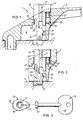
- a vent locking mechanism 1 comprises a handle 3 rotatably mounted, by means of a large rivet or pin 5, on a handle base 7.
- the handle 3 includes a sideways extension or latch (not shown) which, when the handle is in its closed position, is able to engage a recess in, or abut against, the solidly mounted frame of the vent.
- a sideways extension or latch (not shown) which, when the handle is in its closed position, is able to engage a recess in, or abut against, the solidly mounted frame of the vent.
- the handle 3 includes a recess 9 which, when the handle 3 is in its closed position, overlays an opening 11 in the handle base 7.
- the recess 9 is adapted to receive a locking device 13 according to the present invention.
- the locking device 13 comprises a body portion 15 having an aperture 17 therein for receiving a key 19 during unlocking.
- This lower portion 24 is attached to the main body 15 of the locking device 13 by means of a resilient web 25.
- the aperture 17 in the body portion 15 extends from the top of the body portion 15 to a region adjacent the resilient web 25.
- This spindle 27 receives a helical spring 29 within the recess 9 of the handle 3.
- the helical spring 29 sits on a shaped shoulder 31 within the recess 9 and biases the locking device 13 into its unlocked position (as shown in figure 1).
- the locking device 13 further includes a second flange 33 attached via a resilient support 35 to the body portion 15. During use, the second flange 33 engages a corner 37 formed in a wall of the recess 9, thereby dictating the unlocked position of the locking device 13.
- the locking device 13 needs only to be depressed, so that the detent 21 slides past the projection 39 and engages the underside thereof. This is facilitated by the angled bearing surfaces of the detent 21 and projection 39, as shown in the drawings.
- a locking device according to the invention is simple to use and cheap to manufacture, but sufficiently efficient and reliable to satisfy its functional requirements.
- the locking device 13 can be made as a one-piece moulding from plastics materials.
Landscapes
- Centrifugal Separators (AREA)
- Lock And Its Accessories (AREA)
- Non-Silver Salt Photosensitive Materials And Non-Silver Salt Photography (AREA)
- Investigating Or Analysing Biological Materials (AREA)
- Preventing Unauthorised Actuation Of Valves (AREA)
- Quick-Acting Or Multi-Walled Pipe Joints (AREA)
Claims (13)
- Verschlußeinrichtung (13) welche angepaßt ist, während der Benutzung in eine Verschlußposition gedrückt und mittels eines Schlüssels (19) daraus gelöst zu werden , welche umfaßt
einen Körperabschnitt (15) mit einer Öffnung (17) darin zum Aufnehmen eines Schlüssels (19) während des Aufschließens,
einen aktiven Abschnitt (23) zum Ausführen des Verschließens wenn die Einrichtung (13) gedrückt wird,
und eine Arretierung (21), die die Einrichtung (13) in ihrer verschlossenen Position wenn gedrückt hält, dadurch gekennzeichnet, daß die Arretierung (21) an dem Körperabschnitt (15) mittels eines elastischen Steges (25) befestigt ist,
und daß eine Wechselwirkung des Schlüssels (19) mit der Verschlußeinrichtung (13) den elastischen Steg (25) biegt, wodurch die Arretierung (21) deaktiviert und die Einrichtung (13) zurück in ihre unverschlossene Position vorgespannt wird. - Verschlußeinrichtung nach Anspruch 1, welche des weiteren umfaßt Einrichtungen (27) zum Aufnehmen von einer Vorspanneinrichtung (29), welche wenn die Arretierung (21) deaktiviert ist, die Einrichtung (13) zurück in ihre unverschlossene Position zwingt.
- Verschlußeinrichtung nach Anspruch 2, wobei die Aufnahmeeinrichtung (27) eine einstückig mit dem Körperabschnitt (15) gebildete Spindel ist, zum Aufnehmen einer Schraubenfeder (29).
- Verschlußeinrichtung nach einem der vorangehenden Ansprüche, wobei die Arretierung (21) umfaßt einen ersten Flansch, der sich während dem Betrieb in einer Richtung im wesentlichen senkrecht zu der Richtung der Bewegung der Einrichtung erstreckt.
- Verschlußeinrichtung nach einem der vorangegangenen Ansprüche, wobei der aktive Abschnitt (23) und die Arretierung (21) einstückig gebildet sind.
- Verschlußeinrichtung nach einem der vorangegangenen Ansprüche, welche des weiteren umfaßt Einrichtungen (23) zum Bestimmen der unverschlossenen Position der Einrichtung (13).
- Verschlußeinrichtung nach Anspruch 6, wobei die Bestimmungseinrichtungen (33) einen zweiten Flansch umfassen, der sich während der Benutzung in einer Richtung im wesentlichen senkrecht zu der Richtung der Bewegung der Einrichtung erstreckt.
- Verschlußeinrichtung nach Anspruch 7, wobei die Bestimmungseinrichtung (33) an dem Körperabschnitt (15) durch eine elastische Halterung (35) befestigt ist.
- Verschlußeinrichtung nach einem der vorangegangenen Ansprüche, wobei der Körperabschnitt (15) im wesentlichen zylindrisch ist.
- Verschlußeinrichtung nach einem der vorangegangenen Ansprüche, wobei die gesamte Einrichtung (13) hergestellt ist als ein Einstück-Kunststoffguß.
- Lüftungsflügelverschlußmechanismus (1), welcher umfaßt einen Griff (3), eine Basis (7), auf welcher der Griff (3) drehbar befestigt ist und eine Verschlußeinrichtung (13), wobei die Verschlußeinrichtung (13) angepaßt ist während dem Gebrauch in eine mit der Basis (7) eingreifende Verschlußposition gedrückt zu werden, wodurch eine Drehung des Griffes (3) verhindert wird, und daraus ausgelöst zu werden, mittels eines Schlüssels (19), wobei die Verschlußeinrichtung (13) umfaßt einen Körperabschnitt (15), der darin eine Öffnung (17) hat zum Aufnehmen eines Schlüssels (19) während des Aufschließens,
einen aktiven Abschnitt (23) zum Ausführen des Verschließens, wenn die Einrichtung (13) gedrückt wird, und
eine Arretierung (21), die die Einrichtung (13) in ihrer verschlossenen Position, wenn gedrückt hält, dadurch gekennzeichnet, daß die Arretierung (21) an dem Körperabschnitt (15) mittels eines elastischen Steges (25) befestigt ist,
und daß ein Wechselwirken des Schlüssels (19) mit der Verschlußeinrichtung (13) den elastischen Steg (25) biegt, wodurch die Arretierung (21) deaktiviert und die Einrichtung (13) zurück in ihre unverschlossene Position vorgespannt wird. - Lüftungsflügelverschlußmechanismus nach Anspruch 11, wobei wenn die Verschlußeinrichtung (13) gedrückt ist, der aktive Abschnitt (23) in eine Vertiefung in der Basis (7) eintritt und die Arretierung (21) mit einem geformten Teil des Griffes (3) wechselwirkt.
- Lüftungsflügelverschlußmechanismus nach Anspruch 11 oder 12, wobei die Verschlußeinrichtung (13) in eine Vertiefung (9) in dem Griff (3) aufgenommen ist zusammen mit einer Vorspanneinrichtung (29) zum Zwingen der Verschlußeinrichtung in ihre unverschlossene Position.
Applications Claiming Priority (2)
| Application Number | Priority Date | Filing Date | Title |
|---|---|---|---|
| GB9102842 | 1991-02-11 | ||
| GB9102842A GB2252590A (en) | 1991-02-11 | 1991-02-11 | A locking device |
Publications (3)
| Publication Number | Publication Date |
|---|---|
| EP0499740A2 EP0499740A2 (de) | 1992-08-26 |
| EP0499740A3 EP0499740A3 (en) | 1992-09-30 |
| EP0499740B1 true EP0499740B1 (de) | 1995-03-08 |
Family
ID=10689834
Family Applications (1)
| Application Number | Title | Priority Date | Filing Date |
|---|---|---|---|
| EP91309435A Expired - Lifetime EP0499740B1 (de) | 1991-02-11 | 1991-10-15 | Verriegelungseinrichtung |
Country Status (4)
| Country | Link |
|---|---|
| EP (1) | EP0499740B1 (de) |
| AT (1) | ATE119615T1 (de) |
| DE (1) | DE69108006T2 (de) |
| GB (1) | GB2252590A (de) |
Families Citing this family (5)
| Publication number | Priority date | Publication date | Assignee | Title |
|---|---|---|---|---|
| JP2512396Y2 (ja) * | 1991-12-31 | 1996-10-02 | 有限会社鈴商トレーディング | ロック付クレセント |
| GB9405119D0 (en) * | 1994-03-16 | 1994-04-27 | Hardware & Systems Patents Ltd | Improvements in or relating to handle assemblies |
| IES940267A2 (en) * | 1994-03-28 | 1994-08-24 | Patrick J Daly | Fastener including lock |
| GB0010913D0 (en) * | 2000-05-08 | 2000-06-28 | Banks J & Co Ltd | Locking cylinder for a locking handle and method pf assembly thereof |
| GB2414764A (en) * | 2004-06-02 | 2005-12-07 | Trojan Hardware & Designs Ltd | Window handle arrangement |
Family Cites Families (7)
| Publication number | Priority date | Publication date | Assignee | Title |
|---|---|---|---|---|
| GB1124053A (en) * | 1965-10-26 | 1968-08-21 | Metropolitan Plastics Ltd | Improvements in and relating to locks |
| US3767244A (en) * | 1971-05-25 | 1973-10-23 | Stanley Works Pty | Locks |
| US3908235A (en) * | 1974-12-02 | 1975-09-30 | Gregory Alan Telliard | Removable snap fastener |
| US4052093A (en) * | 1976-07-15 | 1977-10-04 | Fattori Lazzaro A | Telescoping rotary latch and manufacture thereof |
| GB2092658B (en) * | 1981-02-11 | 1985-02-27 | Gregg Geoffrey John | Lockable handle assembly |
| GB2222850A (en) * | 1988-09-20 | 1990-03-21 | Map Hardware Limited | Handles |
| IT1229245B (it) * | 1989-05-09 | 1991-07-26 | Mazzucchelli King Plasti | Dispositivo antifurto per articoli dotati di almeno un elemento a stanghetta, in particolare occhiali |
-
1991
- 1991-02-11 GB GB9102842A patent/GB2252590A/en not_active Withdrawn
- 1991-10-15 EP EP91309435A patent/EP0499740B1/de not_active Expired - Lifetime
- 1991-10-15 DE DE69108006T patent/DE69108006T2/de not_active Expired - Fee Related
- 1991-10-15 AT AT91309435T patent/ATE119615T1/de not_active IP Right Cessation
Also Published As
| Publication number | Publication date |
|---|---|
| GB9102842D0 (en) | 1991-03-27 |
| ATE119615T1 (de) | 1995-03-15 |
| EP0499740A2 (de) | 1992-08-26 |
| DE69108006D1 (de) | 1995-04-13 |
| GB2252590A (en) | 1992-08-12 |
| EP0499740A3 (en) | 1992-09-30 |
| DE69108006T2 (de) | 1995-07-20 |
Similar Documents
| Publication | Publication Date | Title |
|---|---|---|
| US5878606A (en) | Door lock for swinging door | |
| US4617810A (en) | Sliding glass door lock | |
| US12054965B2 (en) | Clevis-sensing adjustable hook latch | |
| US7523969B2 (en) | Door entry latch | |
| EP0540902B1 (de) | Verschlusseinrichtung für einen Deckel | |
| US5435609A (en) | Anti-theft apparatus for vehicle door locks | |
| US5826924A (en) | Lock assembly with emergent forcible unlatching from outside | |
| US20050073157A1 (en) | Pull door lock | |
| CA1245008A (en) | Double action crib drop side lock | |
| US5450737A (en) | Removable lock handle assembly | |
| US5909919A (en) | Auxiliary lock assembly with additional interior locking | |
| EP0499740B1 (de) | Verriegelungseinrichtung | |
| EP0241245B2 (de) | Griff | |
| US10718140B1 (en) | Cabinet locking device | |
| JP4325794B2 (ja) | 車両用シートのロック装置 | |
| US7134699B1 (en) | Locking rotary latch | |
| IE67003B1 (en) | Improvements in or relating to handle assemblies | |
| EP1179108B1 (de) | Verschluss | |
| JPH08282277A (ja) | スナッチロック装置 | |
| GB2102484A (en) | Lockable handle device for a casement closure | |
| US4330145A (en) | Double-latch mechanism | |
| GB2191242A (en) | Window fastener | |
| US4683731A (en) | Latching device | |
| JPH08232528A (ja) | スライド扉用ラッチ装置 | |
| JPH041377A (ja) | 車両のドアロック装置 |
Legal Events
| Date | Code | Title | Description |
|---|---|---|---|
| PUAI | Public reference made under article 153(3) epc to a published international application that has entered the european phase |
Free format text: ORIGINAL CODE: 0009012 |
|
| PUAL | Search report despatched |
Free format text: ORIGINAL CODE: 0009013 |
|
| AK | Designated contracting states |
Kind code of ref document: A2 Designated state(s): AT BE CH DE DK ES FR GB GR IT LI LU NL SE |
|
| AK | Designated contracting states |
Kind code of ref document: A3 Designated state(s): AT BE CH DE DK ES FR GB GR IT LI LU NL SE |
|
| 17P | Request for examination filed |
Effective date: 19930316 |
|
| 17Q | First examination report despatched |
Effective date: 19931206 |
|
| GRAA | (expected) grant |
Free format text: ORIGINAL CODE: 0009210 |
|
| AK | Designated contracting states |
Kind code of ref document: B1 Designated state(s): AT BE CH DE DK ES FR GB GR IT LI LU NL SE |
|
| PG25 | Lapsed in a contracting state [announced via postgrant information from national office to epo] |
Ref country code: NL Free format text: LAPSE BECAUSE OF NON-PAYMENT OF DUE FEES Effective date: 19950308 Ref country code: LI Effective date: 19950308 Ref country code: GR Free format text: LAPSE BECAUSE OF FAILURE TO SUBMIT A TRANSLATION OF THE DESCRIPTION OR TO PAY THE FEE WITHIN THE PRESCRIBED TIME-LIMIT Effective date: 19950308 Ref country code: ES Free format text: THE PATENT HAS BEEN ANNULLED BY A DECISION OF A NATIONAL AUTHORITY Effective date: 19950308 Ref country code: CH Effective date: 19950308 Ref country code: BE Effective date: 19950308 Ref country code: AT Effective date: 19950308 |
|
| REF | Corresponds to: |
Ref document number: 119615 Country of ref document: AT Date of ref document: 19950315 Kind code of ref document: T |
|
| REF | Corresponds to: |
Ref document number: 69108006 Country of ref document: DE Date of ref document: 19950413 |
|
| ET | Fr: translation filed | ||
| ITF | It: translation for a ep patent filed | ||
| REG | Reference to a national code |
Ref country code: CH Ref legal event code: PL |
|
| NLV1 | Nl: lapsed or annulled due to failure to fulfill the requirements of art. 29p and 29m of the patents act | ||
| PG25 | Lapsed in a contracting state [announced via postgrant information from national office to epo] |
Ref country code: DK Effective date: 19951015 |
|
| PG25 | Lapsed in a contracting state [announced via postgrant information from national office to epo] |
Ref country code: LU Free format text: LAPSE BECAUSE OF NON-PAYMENT OF DUE FEES Effective date: 19951031 |
|
| PLBE | No opposition filed within time limit |
Free format text: ORIGINAL CODE: 0009261 |
|
| STAA | Information on the status of an ep patent application or granted ep patent |
Free format text: STATUS: NO OPPOSITION FILED WITHIN TIME LIMIT |
|
| 26N | No opposition filed | ||
| PGFP | Annual fee paid to national office [announced via postgrant information from national office to epo] |
Ref country code: FR Payment date: 19961009 Year of fee payment: 6 |
|
| PGFP | Annual fee paid to national office [announced via postgrant information from national office to epo] |
Ref country code: SE Payment date: 19961016 Year of fee payment: 6 |
|
| PGFP | Annual fee paid to national office [announced via postgrant information from national office to epo] |
Ref country code: DE Payment date: 19961018 Year of fee payment: 6 |
|
| PG25 | Lapsed in a contracting state [announced via postgrant information from national office to epo] |
Ref country code: SE Free format text: LAPSE BECAUSE OF NON-PAYMENT OF DUE FEES Effective date: 19971016 |
|
| PG25 | Lapsed in a contracting state [announced via postgrant information from national office to epo] |
Ref country code: FR Free format text: THE PATENT HAS BEEN ANNULLED BY A DECISION OF A NATIONAL AUTHORITY Effective date: 19971031 |
|
| PG25 | Lapsed in a contracting state [announced via postgrant information from national office to epo] |
Ref country code: DE Free format text: LAPSE BECAUSE OF NON-PAYMENT OF DUE FEES Effective date: 19980701 |
|
| EUG | Se: european patent has lapsed |
Ref document number: 91309435.5 |
|
| REG | Reference to a national code |
Ref country code: FR Ref legal event code: ST |
|
| REG | Reference to a national code |
Ref country code: GB Ref legal event code: IF02 |
|
| PGFP | Annual fee paid to national office [announced via postgrant information from national office to epo] |
Ref country code: GB Payment date: 20021009 Year of fee payment: 12 |
|
| PG25 | Lapsed in a contracting state [announced via postgrant information from national office to epo] |
Ref country code: GB Free format text: LAPSE BECAUSE OF NON-PAYMENT OF DUE FEES Effective date: 20031015 |
|
| GBPC | Gb: european patent ceased through non-payment of renewal fee |
Effective date: 20031015 |
|
| PG25 | Lapsed in a contracting state [announced via postgrant information from national office to epo] |
Ref country code: IT Free format text: LAPSE BECAUSE OF NON-PAYMENT OF DUE FEES;WARNING: LAPSES OF ITALIAN PATENTS WITH EFFECTIVE DATE BEFORE 2007 MAY HAVE OCCURRED AT ANY TIME BEFORE 2007. THE CORRECT EFFECTIVE DATE MAY BE DIFFERENT FROM THE ONE RECORDED. Effective date: 20051015 |