EP0499781A1 - Circulation de carburant avec préchauffage de carburant réglé par thermostat, spécialement pour moteurs à combustion interne à compression d'air et à injection de carburant - Google Patents
Circulation de carburant avec préchauffage de carburant réglé par thermostat, spécialement pour moteurs à combustion interne à compression d'air et à injection de carburant Download PDFInfo
- Publication number
- EP0499781A1 EP0499781A1 EP92100395A EP92100395A EP0499781A1 EP 0499781 A1 EP0499781 A1 EP 0499781A1 EP 92100395 A EP92100395 A EP 92100395A EP 92100395 A EP92100395 A EP 92100395A EP 0499781 A1 EP0499781 A1 EP 0499781A1
- Authority
- EP
- European Patent Office
- Prior art keywords
- fuel
- heat exchanger
- changeover valve
- valve
- cooling water
- Prior art date
- Legal status (The legal status is an assumption and is not a legal conclusion. Google has not performed a legal analysis and makes no representation as to the accuracy of the status listed.)
- Granted
Links
Images

Classifications
-
- F—MECHANICAL ENGINEERING; LIGHTING; HEATING; WEAPONS; BLASTING
- F02—COMBUSTION ENGINES; HOT-GAS OR COMBUSTION-PRODUCT ENGINE PLANTS
- F02M—SUPPLYING COMBUSTION ENGINES IN GENERAL WITH COMBUSTIBLE MIXTURES OR CONSTITUENTS THEREOF
- F02M31/00—Apparatus for thermally treating combustion-air, fuel, or fuel-air mixture
- F02M31/02—Apparatus for thermally treating combustion-air, fuel, or fuel-air mixture for heating
- F02M31/16—Other apparatus for heating fuel
-
- F—MECHANICAL ENGINEERING; LIGHTING; HEATING; WEAPONS; BLASTING
- F02—COMBUSTION ENGINES; HOT-GAS OR COMBUSTION-PRODUCT ENGINE PLANTS
- F02M—SUPPLYING COMBUSTION ENGINES IN GENERAL WITH COMBUSTIBLE MIXTURES OR CONSTITUENTS THEREOF
- F02M31/00—Apparatus for thermally treating combustion-air, fuel, or fuel-air mixture
- F02M31/02—Apparatus for thermally treating combustion-air, fuel, or fuel-air mixture for heating
- F02M31/04—Apparatus for thermally treating combustion-air, fuel, or fuel-air mixture for heating combustion-air or fuel-air mixture
- F02M31/10—Apparatus for thermally treating combustion-air, fuel, or fuel-air mixture for heating combustion-air or fuel-air mixture by hot liquids, e.g. lubricants or cooling water
-
- F—MECHANICAL ENGINEERING; LIGHTING; HEATING; WEAPONS; BLASTING
- F02—COMBUSTION ENGINES; HOT-GAS OR COMBUSTION-PRODUCT ENGINE PLANTS
- F02D—CONTROLLING COMBUSTION ENGINES
- F02D2200/00—Input parameters for engine control
- F02D2200/02—Input parameters for engine control the parameters being related to the engine
- F02D2200/06—Fuel or fuel supply system parameters
- F02D2200/0606—Fuel temperature
-
- Y—GENERAL TAGGING OF NEW TECHNOLOGICAL DEVELOPMENTS; GENERAL TAGGING OF CROSS-SECTIONAL TECHNOLOGIES SPANNING OVER SEVERAL SECTIONS OF THE IPC; TECHNICAL SUBJECTS COVERED BY FORMER USPC CROSS-REFERENCE ART COLLECTIONS [XRACs] AND DIGESTS
- Y02—TECHNOLOGIES OR APPLICATIONS FOR MITIGATION OR ADAPTATION AGAINST CLIMATE CHANGE
- Y02T—CLIMATE CHANGE MITIGATION TECHNOLOGIES RELATED TO TRANSPORTATION
- Y02T10/00—Road transport of goods or passengers
- Y02T10/10—Internal combustion engine [ICE] based vehicles
- Y02T10/12—Improving ICE efficiencies
Definitions
- the invention relates to a fuel circuit with thermostatically controlled fuel preheating for preferably air-compressing injection internal combustion engines according to the features specified in the preamble of claim 1.
- the invention has for its object to simplify the generic thermostat-controlled fuel preheating while reducing the weight and space requirements.
- the special type of mounting makes it possible to easily replace the changeover valve if the thermostat is defective without removing the heat exchanger. Cooling water cannot leak when exchanged.
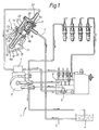
- FIG. 1 shows a fuel circuit 1 with thermostatically controlled fuel preheating 2 for an air-compressing injection internal combustion engine, in which a feed pump 3 sucks fuel from the fuel tank 4 through a feed line 5 via a changeover valve 6, which is controlled as a function of the fuel temperature, and via a prefilter 7 and via a main filter 8 Fuel injection pump 9 promotes.
- the switching valve 6 is designed as a double-acting poppet valve with a wax thermostat as an expansion working element (not shown in detail).
- the poppet valve is guided in a cylindrical recess 10 in such a way that one of its valve plates 6a controls the direct fuel flow and the other opposite valve plate 6b controls the fuel flow via a heat exchanger 11 lying in the way of the coolant flow.
- the heat exchanger 11 and the changeover valve 6 form a structural unit which has a fastening flange 12 as part of the pot-shaped heat exchanger 11 at the end 11a facing the changeover valve 6 and is provided with four through bores 13, 14 for fastening screws, two of which are designated by 15 Fastening screws are used only for fastening the changeover valve 6 and the two fastening screws designated 16 for fastening the changeover valve 6 and heat exchanger 11.
- the heat exchanger housing 16 made of light metal die-cast projects completely into the cooling water flow in the cooling water channel 17 of the cylinder head 18 of the internal combustion engine.
- the interior of this housing 16 is divided into a plurality of chambers 19, through which fuel flows through one after the other, in order to enable sufficient heating of the fuel.
- the heated fuel passes through a fuel supply channel 20 running parallel to the cylindrical recess 10 in the housing 21 of the changeover valve 6 into the cover 22, in order to reach the injection pump 9 through a cover-side outlet connection 23 via the filter arrangement.
- the housing 21 of the changeover valve 6 and the cover 22 are made of plastic and are welded to one another, including the expansion work element and poppet valve, in order to avoid additional fastening elements.
- the mounting flange 12 is provided on its inner edge side with a recess 24 into which the housing 21 of the changeover valve 6 is sealingly fitted.
- the chambers in the heat exchanger 11 are formed by an inserted separating body 25, which on the one hand is sealingly connected to the changeover valve 6 and on the other hand extends at a short distance to the bottom 16a of the heat exchanger housing 16.
- a transverse separating body 26 is additionally provided in the heat exchanger housing 16, so that the fuel emerging from the changeover valve 6 first a chamber 19a, then the chamber 19b from bottom to top flows through a passage 27 in the partition wall 26 and the chamber 19c and the chamber 19d and finally reaches the fuel supply channel 20 and cover 22.
- a further subdivision of the housing interior into a large number of chambers can be provided, which are flowed through in the same manner as described.
- the heat exchanger housing 16 may be ribbed.
Landscapes
- Engineering & Computer Science (AREA)
- Chemical & Material Sciences (AREA)
- Combustion & Propulsion (AREA)
- Mechanical Engineering (AREA)
- General Engineering & Computer Science (AREA)
- Fuel-Injection Apparatus (AREA)
- Cylinder Crankcases Of Internal Combustion Engines (AREA)
- Temperature-Responsive Valves (AREA)
- Combustion Methods Of Internal-Combustion Engines (AREA)
- Combined Controls Of Internal Combustion Engines (AREA)
Priority Applications (1)
| Application Number | Priority Date | Filing Date | Title |
|---|---|---|---|
| AT92100395T ATE103672T1 (de) | 1991-02-20 | 1992-01-11 | Kraftstoffkreislauf mit thermostatgesteuerter kraftstoffvorwaermung fuer vorzugsweise luftverdichtende einspritzbrennkraftmaschinen. |
Applications Claiming Priority (2)
| Application Number | Priority Date | Filing Date | Title |
|---|---|---|---|
| DE4105232A DE4105232C1 (fr) | 1991-02-20 | 1991-02-20 | |
| DE4105232 | 1991-02-20 |
Publications (2)
| Publication Number | Publication Date |
|---|---|
| EP0499781A1 true EP0499781A1 (fr) | 1992-08-26 |
| EP0499781B1 EP0499781B1 (fr) | 1994-03-30 |
Family
ID=6425456
Family Applications (1)
| Application Number | Title | Priority Date | Filing Date |
|---|---|---|---|
| EP92100395A Expired - Lifetime EP0499781B1 (fr) | 1991-02-20 | 1992-01-11 | Circulation de carburant avec préchauffage de carburant réglé par thermostat, spécialement pour moteurs à combustion interne à compression d'air et à injection de carburant |
Country Status (6)
| Country | Link |
|---|---|
| US (1) | US5163410A (fr) |
| EP (1) | EP0499781B1 (fr) |
| JP (1) | JPH0814268B2 (fr) |
| AT (1) | ATE103672T1 (fr) |
| DE (1) | DE4105232C1 (fr) |
| ES (1) | ES2054509T3 (fr) |
Cited By (2)
| Publication number | Priority date | Publication date | Assignee | Title |
|---|---|---|---|---|
| GB2265416A (en) * | 1992-03-24 | 1993-09-29 | Croll Marlene Frances | Valve control of fluid flow temperature. |
| EP0836002A3 (fr) * | 1996-10-10 | 1998-11-04 | Daimler-Benz Aktiengesellschaft | Dispositif de transfert de chaleur entre fluides en écoulement pour un moteur à combustion |
Families Citing this family (6)
| Publication number | Priority date | Publication date | Assignee | Title |
|---|---|---|---|---|
| JP3063050B2 (ja) * | 1993-08-13 | 2000-07-12 | 義一 久世 | 定温水制御サーモスタットとそれによる電子燃料噴射装置の定温水制御方法 |
| DE10028007A1 (de) * | 2000-06-06 | 2001-08-30 | Daimler Chrysler Ag | Kraftstoffeinspritzvorrichtung mit Niederdruck-Kreislauf |
| KR100974718B1 (ko) * | 2008-07-09 | 2010-08-06 | 기아자동차주식회사 | 디젤엔진용 연료필터의 히팅장치 |
| DE102014001880A1 (de) * | 2014-02-14 | 2015-08-20 | Deutz Aktiengesellschaft | Verfahren zum Reinigen von Dieselmotorenabgassen |
| DE102014001879A1 (de) * | 2014-02-14 | 2015-08-20 | Deutz Aktiengesellschaft | Brennkraftmaschine |
| CN115095454A (zh) * | 2022-08-25 | 2022-09-23 | 江苏普瑞亚动力科技有限公司 | 一种带有热回收结构的发动机油控系统 |
Citations (4)
| Publication number | Priority date | Publication date | Assignee | Title |
|---|---|---|---|---|
| US4387692A (en) * | 1981-01-19 | 1983-06-14 | Blackschleger Douglas H | Petroleum preheating device for engines |
| EP0094885A1 (fr) * | 1982-05-17 | 1983-11-23 | Automobiles Citroen | Réchauffeur de gazole pour moteur Diesel |
| DE3538360C1 (de) * | 1985-10-29 | 1986-11-06 | Daimler-Benz Ag, 7000 Stuttgart | Kraftstoffkreislauf mit thermostatgesteuerter Kraftstoffvorwärmung für eine luftverdichtende Einspritzbrennkraftmaschine |
| EP0301959A1 (fr) * | 1987-07-31 | 1989-02-01 | Automobiles Peugeot | Boîtier de sortie de liquide de refroidissement pour moteur Diesel |
Family Cites Families (8)
| Publication number | Priority date | Publication date | Assignee | Title |
|---|---|---|---|---|
| US1467497A (en) * | 1923-09-11 | Charles w | ||
| JPS59108859A (ja) * | 1982-12-14 | 1984-06-23 | Isuzu Motors Ltd | デイ−ゼルエンジンの燃料加熱装置 |
| DE3514071A1 (de) * | 1985-04-18 | 1986-10-23 | Josef Mattighofen Fuchs | Vorrichtung zum vorwaermen von dieselkraftstoff fuer ein kraftfahrzeug mit dieselmotor |
| DE3630084A1 (de) * | 1986-09-04 | 1988-03-17 | Hengst Walter Gmbh & Co Kg | Kraftstoff-vorwaermer |
| US4754741A (en) * | 1987-01-29 | 1988-07-05 | Stirling Power Systems Corporation | Fuel conditioner assembly |
| US4934330A (en) * | 1988-10-28 | 1990-06-19 | Keith Lindsay | Fuel tank heater |
| US5048501A (en) * | 1989-03-27 | 1991-09-17 | Smith Dale T | Fuel economy system for internal combustion engines |
| US5042447A (en) * | 1990-10-11 | 1991-08-27 | Parker Hannifin Corporation | Thermostatically controlled fuel heater and cooler |
-
1991
- 1991-02-20 DE DE4105232A patent/DE4105232C1/de not_active Expired - Lifetime
-
1992
- 1992-01-11 ES ES92100395T patent/ES2054509T3/es not_active Expired - Lifetime
- 1992-01-11 AT AT92100395T patent/ATE103672T1/de not_active IP Right Cessation
- 1992-01-11 EP EP92100395A patent/EP0499781B1/fr not_active Expired - Lifetime
- 1992-02-14 JP JP4075093A patent/JPH0814268B2/ja not_active Expired - Lifetime
- 1992-02-19 US US07/836,878 patent/US5163410A/en not_active Expired - Fee Related
Patent Citations (4)
| Publication number | Priority date | Publication date | Assignee | Title |
|---|---|---|---|---|
| US4387692A (en) * | 1981-01-19 | 1983-06-14 | Blackschleger Douglas H | Petroleum preheating device for engines |
| EP0094885A1 (fr) * | 1982-05-17 | 1983-11-23 | Automobiles Citroen | Réchauffeur de gazole pour moteur Diesel |
| DE3538360C1 (de) * | 1985-10-29 | 1986-11-06 | Daimler-Benz Ag, 7000 Stuttgart | Kraftstoffkreislauf mit thermostatgesteuerter Kraftstoffvorwärmung für eine luftverdichtende Einspritzbrennkraftmaschine |
| EP0301959A1 (fr) * | 1987-07-31 | 1989-02-01 | Automobiles Peugeot | Boîtier de sortie de liquide de refroidissement pour moteur Diesel |
Cited By (3)
| Publication number | Priority date | Publication date | Assignee | Title |
|---|---|---|---|---|
| GB2265416A (en) * | 1992-03-24 | 1993-09-29 | Croll Marlene Frances | Valve control of fluid flow temperature. |
| GB2265416B (en) * | 1992-03-24 | 1995-08-30 | Croll Marlene Frances | A fluid temperature regulating assembly |
| EP0836002A3 (fr) * | 1996-10-10 | 1998-11-04 | Daimler-Benz Aktiengesellschaft | Dispositif de transfert de chaleur entre fluides en écoulement pour un moteur à combustion |
Also Published As
| Publication number | Publication date |
|---|---|
| JPH0599086A (ja) | 1993-04-20 |
| DE4105232C1 (fr) | 1992-07-16 |
| US5163410A (en) | 1992-11-17 |
| ATE103672T1 (de) | 1994-04-15 |
| ES2054509T3 (es) | 1994-08-01 |
| EP0499781B1 (fr) | 1994-03-30 |
| JPH0814268B2 (ja) | 1996-02-14 |
Similar Documents
| Publication | Publication Date | Title |
|---|---|---|
| EP0671552B1 (fr) | Système de refroidissement pour un moteur à combustion interne | |
| DE4481079B4 (de) | Kühlsystem eines Verbrennungsmotors | |
| DE10117090B4 (de) | Wassergekühlte, mehrzylindrige Brennkraftmaschine | |
| EP0499781A1 (fr) | Circulation de carburant avec préchauffage de carburant réglé par thermostat, spécialement pour moteurs à combustion interne à compression d'air et à injection de carburant | |
| DE69105633T2 (de) | Kühlungsanlage für Brennkraftmaschinen. | |
| DE19628542A1 (de) | Kühlsystem für einen Verbrennungsmotor | |
| DE10129933B4 (de) | Wassergekühlte Brennkraftmaschine, insbesondere für Motorräder | |
| DE2916691C2 (de) | Kühlvorrichtung für Brennkraftmaschinen | |
| DE4432292B4 (de) | Verteilereinrichtung für das Kühl- bzw. Heizsystem von Fahrzeugen mit Verbrennungsmotoren | |
| DE102006007757A1 (de) | Wärmespeichertank | |
| DE2739605C3 (de) | Ansaugkasten für Brennkraftmaschinen | |
| DE4342799C2 (de) | Ölgekühlte Hubkolben-Brennkraftmaschine | |
| DE10021525A1 (de) | Kühlkreislauf für eine mehrzylindrige Brennkraftmaschine | |
| DE10021526C2 (de) | Anordnung zur Kühlung einer mehrzylindrigen Brennkraftmaschine | |
| EP0998624B1 (fr) | Unite de conditionnement pour huile lubrifiante | |
| DE3701385C1 (en) | Piston internal combustion engine with liquid cooling | |
| EP0905453B2 (fr) | Réchauffeur d'eau chaude sanitaire | |
| DE10244829A1 (de) | Flüssigkeitsgekühlte Brennkraftmaschine sowie Verfahren zur Durchführung eines Abwärmetransfers | |
| DE4202572C2 (de) | Schmier- und/oder Kühlölversorgung für eine Maschine, insbesondere eine Brennkraftmaschine | |
| DE60316077T2 (de) | Modul für einen Kühlungskreislauf und Kreislauf mit solchem Modul | |
| DE4210627A1 (de) | Brennkraftmaschine mit einem Kühlkreislauf | |
| AT410713B (de) | Wasserheizanlage | |
| DE3825176A1 (de) | Bausteinfoermiges kombiniertes filtergeraet | |
| AT405329B (de) | Wasserheizanlage mit einem primärwärmetauscher | |
| DE2726095A1 (de) | Baugruppe fuer brennkraftmaschinen |
Legal Events
| Date | Code | Title | Description |
|---|---|---|---|
| PUAI | Public reference made under article 153(3) epc to a published international application that has entered the european phase |
Free format text: ORIGINAL CODE: 0009012 |
|
| 17P | Request for examination filed |
Effective date: 19920606 |
|
| AK | Designated contracting states |
Kind code of ref document: A1 Designated state(s): AT ES FR GB IT SE |
|
| 17Q | First examination report despatched |
Effective date: 19930423 |
|
| ITF | It: translation for a ep patent filed | ||
| GRAA | (expected) grant |
Free format text: ORIGINAL CODE: 0009210 |
|
| AK | Designated contracting states |
Kind code of ref document: B1 Designated state(s): AT ES FR GB IT SE |
|
| REF | Corresponds to: |
Ref document number: 103672 Country of ref document: AT Date of ref document: 19940415 Kind code of ref document: T |
|
| GBT | Gb: translation of ep patent filed (gb section 77(6)(a)/1977) |
Effective date: 19940421 |
|
| ET | Fr: translation filed | ||
| REG | Reference to a national code |
Ref country code: ES Ref legal event code: FG2A Ref document number: 2054509 Country of ref document: ES Kind code of ref document: T3 |
|
| EAL | Se: european patent in force in sweden |
Ref document number: 92100395.0 |
|
| PLBE | No opposition filed within time limit |
Free format text: ORIGINAL CODE: 0009261 |
|
| STAA | Information on the status of an ep patent application or granted ep patent |
Free format text: STATUS: NO OPPOSITION FILED WITHIN TIME LIMIT |
|
| 26N | No opposition filed | ||
| REG | Reference to a national code |
Ref country code: FR Ref legal event code: TP |
|
| REG | Reference to a national code |
Ref country code: GB Ref legal event code: 732E |
|
| REG | Reference to a national code |
Ref country code: GB Ref legal event code: 732E |
|
| PGFP | Annual fee paid to national office [announced via postgrant information from national office to epo] |
Ref country code: GB Payment date: 19991222 Year of fee payment: 9 |
|
| PGFP | Annual fee paid to national office [announced via postgrant information from national office to epo] |
Ref country code: ES Payment date: 20000120 Year of fee payment: 9 |
|
| PGFP | Annual fee paid to national office [announced via postgrant information from national office to epo] |
Ref country code: FR Payment date: 20000125 Year of fee payment: 9 Ref country code: AT Payment date: 20000125 Year of fee payment: 9 |
|
| PGFP | Annual fee paid to national office [announced via postgrant information from national office to epo] |
Ref country code: SE Payment date: 20000126 Year of fee payment: 9 |
|
| PG25 | Lapsed in a contracting state [announced via postgrant information from national office to epo] |
Ref country code: GB Free format text: LAPSE BECAUSE OF NON-PAYMENT OF DUE FEES Effective date: 20010111 Ref country code: AT Free format text: LAPSE BECAUSE OF NON-PAYMENT OF DUE FEES Effective date: 20010111 |
|
| PG25 | Lapsed in a contracting state [announced via postgrant information from national office to epo] |
Ref country code: SE Free format text: LAPSE BECAUSE OF NON-PAYMENT OF DUE FEES Effective date: 20010112 Ref country code: ES Free format text: LAPSE BECAUSE OF NON-PAYMENT OF DUE FEES Effective date: 20010112 |
|
| GBPC | Gb: european patent ceased through non-payment of renewal fee |
Effective date: 20010111 |
|
| EUG | Se: european patent has lapsed |
Ref document number: 92100395.0 |
|
| PG25 | Lapsed in a contracting state [announced via postgrant information from national office to epo] |
Ref country code: FR Free format text: LAPSE BECAUSE OF NON-PAYMENT OF DUE FEES Effective date: 20010928 |
|
| REG | Reference to a national code |
Ref country code: FR Ref legal event code: ST |
|
| REG | Reference to a national code |
Ref country code: ES Ref legal event code: FD2A Effective date: 20020916 |
|
| PG25 | Lapsed in a contracting state [announced via postgrant information from national office to epo] |
Ref country code: IT Free format text: LAPSE BECAUSE OF NON-PAYMENT OF DUE FEES Effective date: 20050111 |