EP0499846B2 - Biegering-Kraftaufnehmer - Google Patents
Biegering-Kraftaufnehmer Download PDFInfo
- Publication number
- EP0499846B2 EP0499846B2 EP92101435A EP92101435A EP0499846B2 EP 0499846 B2 EP0499846 B2 EP 0499846B2 EP 92101435 A EP92101435 A EP 92101435A EP 92101435 A EP92101435 A EP 92101435A EP 0499846 B2 EP0499846 B2 EP 0499846B2
- Authority
- EP
- European Patent Office
- Prior art keywords
- ring
- force
- flex
- introduction
- bearing
- Prior art date
- Legal status (The legal status is an assumption and is not a legal conclusion. Google has not performed a legal analysis and makes no representation as to the accuracy of the status listed.)
- Expired - Lifetime
Links
- 229920001343 polytetrafluoroethylene Polymers 0.000 claims description 3
- 239000004810 polytetrafluoroethylene Substances 0.000 claims description 3
- 229920001971 elastomer Polymers 0.000 claims description 2
- 239000000806 elastomer Substances 0.000 claims description 2
- 230000033001 locomotion Effects 0.000 abstract description 18
- 238000005452 bending Methods 0.000 abstract description 10
- 230000005540 biological transmission Effects 0.000 description 20
- 238000005259 measurement Methods 0.000 description 4
- 238000000034 method Methods 0.000 description 2
- 238000006073 displacement reaction Methods 0.000 description 1
- 238000011156 evaluation Methods 0.000 description 1
- 239000000463 material Substances 0.000 description 1
- 239000004033 plastic Substances 0.000 description 1
- -1 polytetrafluoroethylene Polymers 0.000 description 1
- 238000005096 rolling process Methods 0.000 description 1
Images


Classifications
-
- G—PHYSICS
- G01—MEASURING; TESTING
- G01G—WEIGHING
- G01G3/00—Weighing apparatus characterised by the use of elastically-deformable members, e.g. spring balances
- G01G3/12—Weighing apparatus characterised by the use of elastically-deformable members, e.g. spring balances wherein the weighing element is in the form of a solid body stressed by pressure or tension during weighing
- G01G3/14—Weighing apparatus characterised by the use of elastically-deformable members, e.g. spring balances wherein the weighing element is in the form of a solid body stressed by pressure or tension during weighing measuring variations of electrical resistance
- G01G3/1402—Special supports with preselected places to mount the resistance strain gauges; Mounting of supports
- G01G3/141—Special supports with preselected places to mount the resistance strain gauges; Mounting of supports the supports being disc or ring shaped
-
- G—PHYSICS
- G01—MEASURING; TESTING
- G01L—MEASURING FORCE, STRESS, TORQUE, WORK, MECHANICAL POWER, MECHANICAL EFFICIENCY, OR FLUID PRESSURE
- G01L1/00—Measuring force or stress, in general
- G01L1/20—Measuring force or stress, in general by measuring variations in ohmic resistance of solid materials or of electrically-conductive fluids; by making use of electrokinetic cells, i.e. liquid-containing cells wherein an electrical potential is produced or varied upon the application of stress
- G01L1/22—Measuring force or stress, in general by measuring variations in ohmic resistance of solid materials or of electrically-conductive fluids; by making use of electrokinetic cells, i.e. liquid-containing cells wherein an electrical potential is produced or varied upon the application of stress using resistance strain gauges
- G01L1/2206—Special supports with preselected places to mount the resistance strain gauges; Mounting of supports
- G01L1/2231—Special supports with preselected places to mount the resistance strain gauges; Mounting of supports the supports being disc- or ring-shaped, adapted for measuring a force along a single direction
Definitions
- the invention relates to jump ring force transducers with an outer bearing ring and an inner one Force application body, each with an inner or outer annular power transmission web with one concentrically arranged in between Jump ring are connected in axial Strain gauges spaced from each other wearing.
- this jump ring force transducer is a relatively low hysteresis. As a hysteresis or reversal margin will be the difference of at same load when loading or unloading received signals referred to.
- EP-A2-465 881 Another known transducer (EP-A2-465 881) has no jump ring. The introduction of force not only from above, but also from below central, so that the problem of friction Hysteresis error does not pose. Furthermore the concentric pipe section shown there is supported not on the load-bearing surface, but is on the edge of a relatively thick housing plate educated.
- the object of the invention is therefore another Reduction of the hysteresis error with jump ring load cells to reach.
- This task is according to the invention with the features of independent Claims solved - 1, 2, 3, 6, 11.
- the force can be applied so that the occurring radial movements do not lead to friction, but only to slightly deform one deformable component.
- the bearing ring can be reached via a Concentric thin-walled pipe section supported will. With high axial rigidity this is Pipe piece radially so elastic that it is under the influence of the radial movements is deformed, without friction.
- the introduction of force can also be carried out in a corresponding manner on the inner force transmission body a concentric thin-walled piece of pipe is made, to avoid radial forces.
- the inventive concept becomes a force transmission without radial force achieved on the bearing ring in that the Bearing ring axially over a ring land with a concentric Support ring is connected, which in turn supported on an annular support surface is whose diameter is smaller than the diameter of the ring bridge.
- the outer bearing ring tilts with axial force transmission to the upper edge of the Jump rings. That over the ring-shaped support surface connected support ring moves because of the shift inward Force application point in opposite Direction. In this way it can be achieved that the power transmission web on which the Jump ring is connected, does not move radially.
- an elastomeric bearing is used, preferably a bearing made of PTFE (polytetrafluoroethylene).
- radial movements and friction Avoiding radial forces can, according to the invention radial forces and also be provided to allow frictional radial movements the application of force to such Make sure that this does not affect the Jump ring is. According to an embodiment of the inventive concept this happens because the force transmission on the force transmission body and / or on the bearing ring in a plane that at least approximated with the ring-shaped transmission webs containing middle plane coincides.
- the jump ring force transducer shown in Fig. 1 has an outer bearing ring 1, which on a surface 2 supports.
- the force to be measured is axially in the direction of an arrow 3 on a inner force application body 4 applied.
- a bending ring concentrically 5 arranged with the force introduction body 4 via an annular power transmission web 6 and with the bearing ring 1 via a annular power transmission web 7 connected is that each form joints and in a common Level.
- strain gauges 8 are applied, for example strain gauges that when stretching or compressing their electrical Change resistance and this way measurement signal corresponding to the force to be measured deliver to an evaluation circuit (not shown).
- the bending ring 5 deforms in the Way that he is at his top inside and tilts outwards at its bottom, causing the strain gauges attached above 8 upset and the ones attached below Strain gauges 8 are stretched.
- FIG. 1 is through two annular recesses 9 in the lower area the bearing ring 1 is a concentric thin-walled Pipe piece 10 formed, which is on the surface 2nd supports.
- This pipe section 10 is in the axial direction sufficiently rigid to withstand the force to be measured transferred to; in the radial direction is the pipe section 10 but very elastic.
- the one with a load of the jump ring force transducer Deformation of the bearing ring 1 therefore does not lead to a radial movement with friction, but is caused by a deformation of the pipe section 10 caught. This will make the jump ring 5 and especially the strain gauges attached to it 8 of any radial forces Keep free when applying force to bearing ring 1.
- a radial force influence be avoided.
- the axial force to be measured is initiated via a pendulum body 11, with a spherical surface 12 on a Thrust washer 13 supports.
- the thrust washer 13 is over a concentric thin-walled piece of pipe 14 on an inner shoulder 15 of the force introduction body 4 supported.
- the support surface 1a on which the bearing ring 1 is supported is displaced so far inwards that it lies approximately on the same diameter as the outer force transmission web 7.
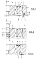
- the bearing ring 1 is connected axially via an annular web 16 which forms a flexible joint to a concentric support ring 17 which has the annular support surface 18 on its underside.
- the support ring 17 is separated from the bearing ring 1 by an inner radial groove 16a which extends to the ring web 16 and is formed by a recess.
- a further groove 16b is pierced on the opposite side of the ring web 16.
- the diameter of the annular support surface 18 is selected to be smaller than the diameter of the ring web 16. This results in the deformation schematically indicated in FIG. 4a when loaded.
- the bearing ring 1 inclines with its upper side towards the bending ring 5; the support ring 17 moves in the opposite direction. These two pivoting movements are each indicated with arrows in FIG. 4a. It can thereby be achieved that the force transmission web 7 does not move radially, so that the deformation of the bearing ring 1 has no influence on the bending ring 5.
- Fig. 4c differs differ from the embodiment of Fig. 4b only in that the groove 16b 'is omitted. This closes the ring land 16 ", the Support ring 17 "connects to the bearing ring 1, radially outwards to the support ring 17 "; resulting deformation movement is shown in Fig. 4c and corresponds to that in FIGS. 4a and 4b described movement.
- Fig. 5 it is shown that the support of the Bearing rings 1 on an outer shoulder 1b.
- This shoulder 1b is approximately in the through Power transmission webs 6 and 7 of the jump ring 5 certain normal level. Although radial forces when force is applied to the bearing ring 1 occur, these radial forces remain without influence on the measurement.
- the 6 shows the introduction of force on the inner force introduction body 4 in the plane, which also the power transmission webs 6 and 7 of Jump rings 5 contains.
- a pendulum support supports this 11 on a pressure piece 18, which on an inner shoulder 4a of the force introduction body 4 lies.
- FIG. 7 it is shown that when the force is applied generated on the inner force introduction body 4 Radial forces through the use of a disc-shaped Elastomeric bearing 20 largely excluded or at least be greatly reduced can.
- a pendulum support 1 rests on a pressure piece 21, which extends over the elastomer bearing 20 supported on the force introduction body 4.
- a jump ring force transducer is shown in which the force is applied via a pendulum support 11 takes place, the lower ball pressure surface 22nd has a radius that approximates the height of the Pendulum support 11 corresponds. Because the radii of the two Ball pressure surfaces of the pendulum support 11 die lateral displacement of the force application surface a deflection can determine these radii not be made much larger than that Height of the pendulum support 11. Because of the jump ring load cell and with it the inner force application body 4 but in a heat treated condition is present, which does not have very high surface pressures would allow, that with the described Radius executed ball pressure surface 22 too proportionate high radial forces at the point of force application to lead.
- the force is applied to the inner force introduction body 4 via a also as a pendulum support executed ball thrust piece 25, which over a ball pressure surface 26 on a frustoconical Pressure piece 27 supports.
- This frustoconical Pressure piece 27 is in a central conical bore 28 with matching Cone angle in the force introduction body 4 added.
- the pressure load between the ball pressure surface 26 and the flat top of the pressure piece 27 caused radial movement is caused by an opposite radial movement compensated by the on the cone surface occurring, in the pressure piece 27 radially inward forces is caused.
- the choice of the cone angle thus allows achieve that a sliding movement between the Ball pressure surface 26 and the top of the pressure piece 27 is largely avoided.
- the between the frustoconical pressure piece 27 and the conical bore 28 occurring Supporting forces are perpendicular to the contact surface, so that the frustoconical Thrust piece 27 and the conical bore 28 to transmit measuring force without sliding motion.
- the cone angle is preferably in the range of 40 to 50 ° selected.
Landscapes
- Physics & Mathematics (AREA)
- General Physics & Mathematics (AREA)
- Support Of The Bearing (AREA)
- Preparation Of Compounds By Using Micro-Organisms (AREA)
- Saccharide Compounds (AREA)
- Diaphragms For Electromechanical Transducers (AREA)
- Prostheses (AREA)
- Force Measurement Appropriate To Specific Purposes (AREA)
Description
Bei dem Ausführungsbeispiel nach Fig. 4 ist der Lagerring 1 axial über einen ein Biegegelenk bildenden Ringsteg 16 mit einem konzentrischen Abstützring 17 verbunden, der an seiner Unterseite die ringförmige Abstützfläche 18 aufweist. Am inneren Durchmesser des Lagerrings 1 ist der Abstützring 17 durch eine sich bis zum Ringsteg 16 erstreckende innere radiale Nut 16a, die von einem Einstich gebildet wird, vom Lagerring 1 getrennt. Auf der gegenüberliegenden Seite des Ringstegs 16 ist eine weitere Nut 16b eingestochen. Der Durchmesser der ringförmigen Abstützfläche 18 ist kleiner gewählt als der Durchmesser des Ringstegs 16. Dadurch ergibt sich bei Belastung die in Fig. 4a schematisch angedeutete Verformung. Der Lagerring 1 neigt sich mit seiner Oberseite zum Biegering 5 hin; der Abstützring 17 bewegt sich in entgegengesetzter Richtung. Diese beiden Schwenkbewegungen sind in Fig. 4a jeweils mit Pfeilen angedeutet. Dadurch kann erreicht werden, daß sich der Kraftübertragungssteg 7 radial nicht verlagert, so daß die Verformung des Lagerrings 1 ohne Einfluß auf den Biegering 5 bleibt.
Claims (11)
- Biegering-Kraftaufnehmer mit einem äußeren Lagerring (1) und einem inneren Krafteinleitungkörper (4), die jeweils über einen inneren bzw. äußeren ringförmigen Kraftübertragungssteg (6, 7) mit einem konzentrisch dazwischen angeordneten Biegering (5) verbunden sind, der in axialem Abstand zueinander angeordnete Dehnungsmeßelemente (8) trägt, dadurch gekennzeichnet, daß der Biegering (5) in der Weise von reibungsbehafteten Radialkrafteinflüssen bei der Krafteinleitung am Lagerring (1) freigehalten ist, daß die Krafteinleitung am Lagerring (1) radialkraftfrei erfolgt, indem der Lagerring (1) über ein konzentrisches dünnwandiges Rohrstück (10) abgestützt ist, das sich unmittelbar auf einer Fläche (2) abstützt.
- Biegering-Kraftaufnehmer mit einem äußeren Lagerring (1) und einem inneren Krafteinleitungkörper (4), die jeweils über einen inneren bzw. äußeren ringförmigen Kraftübertragungssteg (6, 7) mit einem konzentrisch dazwischen angeordneten Biegering (5) verbunden sind, der in axialem Abstand zueinander angeordnete Dehnungsmeßelemente (8) trägt, dadurch gekennzeichnet, daß der Biegering (5) in der Weise von reibungsbehafteten Radialkrafteinflüssen bei der Krafteinleitung am Lagerring (1) freigehalten ist, daß die Krafteinleitung am Lagerring (1) radialkraftfrei erfolgt, indem eine ringförmige Abstützfläche (1a) des Lagerrings (1) auf gleichem Durchmesser liegt wie der äußere Kraftübertragungssteg (7) des Biegerings (5).
- Biegering-Kraftaufnehmer mit einem äußeren Lagerring (1) und einem inneren Krafteinleitungkörper (4), die jeweils über einen inneren bzw. äußeren ringförmigen Kraftübertragungssteg (6, 7) mit einem konzentrisch dazwischen angeordneten Biegering (5) verbunden sind, der in axialem Abstand zueinander angeordnete Dehnungsmeßelemente (8) trägt, dadurch gekennzeichnet, daß der Biegering (5) in der Weise von reibungsbehafteten Radialkrafteinflüssen bei der Krafteinleitung am Lagerring (1) freigehalten ist, daß die Krafteinleitung am Lagerring (1) radialkraftfrei erfolgt, indem der Lagerring (1) über einen ein Biegegelenk bildenden Ringsteg (16, 16', 16") mit einem konzentrischen Abstützring (17, 17', 17") verbunden ist und daß der Abstützring (17, 17', 17") auf einer ringförmigen Abstützfläche (18) abgestützt ist, deren Durchmesser kleiner als der Durchmesser des Ringstegs (16) ist.
- Biegering-Kraftaufnehmer nach Anspruch 3, dadurch gekennzeichnet, daß der Abstützring (17, 17', 17") durch eine innere radiale Nut (16a) am inneren Durchmesser des Lagerrings (1) von diesem getrennt ist.
- Biegering-Kraftaufnehmer nach Anspruch 4, dadurch gekennzeichnet, daß auf der inneren radialen Nut (16a) gegenüberliegenden Seite des Ringstegs (16, 16') eine weitere Nut (16b, 16b') eingestochen ist.
- Biegering-Kraftaufnehmer mit einem äußeren Lagerring (1) und einem inneren Krafteinleitungskörper (4), die jeweils über einen inneren bzw. äußeren ringförmigen Kraftübertragungssteg (6, 7) mit einem konzentrisch dazwischen angeordneten Biegering (5) verbunden sind, der in axialem Abstand zueinander angeordnete Dehnungsmeßelemente (8) trägt, dadurch gekennzeichnet, daß der Biegering (5) in der Weise von reibungsbehafteten Radialkrafteinflüssen bei der Krafteinleitung am Krafteinleitungskörper (4) freigehalten ist, daß die Krafteinleitung am Krafteinleitungskörper (4) radialkraftfrei erfolgt.
- Biegering-Kraftaufnehmer nach Anspruch 6, dadurch gekennzeichnet, daß die Krafteinleitung über ein Elastomer-Lager (20) erfolgt, vorzugsweise ein Lager aus PTFE.
- Biegering-Kraftaufnehmer nach Anspruch 6, dadurch gekennzeichnet, daß die Krafteinleitung über ein konzentrisches dünnwandiges Rohrstück (14) erfolgt.
- Biegering-Kraftaufnehmer nach Anspruch 6, dadurch gekennzeichnet, daß die Krafteinleitung über ein Kugeldruckstück (25) erfolgt, das sich über eine Kugeldruckfläche (26) an einem kegelstumpfförmigen Druckstück (27) abstützt, und daß das kegelstumpfförmige Druckstück (27) in einer zentrischen konischen Bohrung (28) des Krafteinleitungskörpers (4) aufgenommen ist.
- Biegering-Kraftaufnehmer nach Anspruch 6, dadurch gekennzeichnet, daß die Krafteinleitung über eine Pendelstütze (11) erfolgt, die sich mit einer Kugeldruckfläche (22) an einem gehärteten Druckstück (23) abstützt, das sich wiederum mit einer Kugeldruckfläche (24) mit größerem Kugelradius am Krafteinleitungskörper (4) abstützt.
- Biegering-Kraftaufnehmer mit einem äußeren Lagerring (1) und einem inneren Krafteinleitungskörper (4), die jeweils über einen inneren bzw. äußeren ringförmigen Kraftübertragungssteg (6, 7) mit einem konzentrisch dazwischen angeordneten Biegering (5) verbunden sind, der in axialem Abstand zueinander angeordnete Dehnungsmeßelemente (8) trägt, dadurch gekennzeichnet, daß der Biegering (5) in der Weise von reibungsbehafteten Radialkrafteinflüssen bei der Krafteinleitung am Lagerring (1) freigehalten ist, daß die Krafteinleitung am Lagerring (1) in einer Ebene erfolgt, die mindestens angenähert mit der die ringförmigen Kraftübertragungsstege (6, 7) enthaltenden Mittelebene zusammenfällt.
Applications Claiming Priority (2)
| Application Number | Priority Date | Filing Date | Title |
|---|---|---|---|
| DE4104926A DE4104926A1 (de) | 1991-02-18 | 1991-02-18 | Biegering-kraftaufnehmer |
| DE4104926 | 1991-02-18 |
Publications (3)
| Publication Number | Publication Date |
|---|---|
| EP0499846A1 EP0499846A1 (de) | 1992-08-26 |
| EP0499846B1 EP0499846B1 (de) | 1995-04-05 |
| EP0499846B2 true EP0499846B2 (de) | 1998-03-11 |
Family
ID=6425264
Family Applications (1)
| Application Number | Title | Priority Date | Filing Date |
|---|---|---|---|
| EP92101435A Expired - Lifetime EP0499846B2 (de) | 1991-02-18 | 1992-01-29 | Biegering-Kraftaufnehmer |
Country Status (4)
| Country | Link |
|---|---|
| EP (1) | EP0499846B2 (de) |
| AT (1) | ATE120853T1 (de) |
| DE (2) | DE4104926A1 (de) |
| ES (1) | ES2072637T3 (de) |
Families Citing this family (9)
| Publication number | Priority date | Publication date | Assignee | Title |
|---|---|---|---|---|
| DE4442663A1 (de) * | 1994-11-30 | 1996-06-05 | Gassmann Theiss Messtech | Mehrkomponentenaufnehmer |
| DE19514916A1 (de) * | 1995-04-22 | 1996-10-24 | Gassmann Theiss Messtech | Vorrichtung zur Kraftmessung mittels eines elektromechanischen Kraftaufnehmers |
| DE19609921C2 (de) * | 1996-03-14 | 1998-09-10 | Tedea Huntleigh Europ Ltd | Vorrichtung zur Kraftmessung mit einer elektromechanischen Wägezelle |
| DE19917020C2 (de) * | 1999-04-15 | 2001-09-13 | Dieter Michael Krone | Meßbuchse zur Erfassung von radialen Lagerkräften |
| DE19960786A1 (de) * | 1999-12-16 | 2001-06-21 | Schenck Process Gmbh | Radialkraftaufnehmer |
| CZ298400B6 (cs) * | 2005-05-23 | 2007-09-19 | Fakulta strojní CVUT v Praze | Teleso silového snímace |
| DE102006024385A1 (de) * | 2006-05-24 | 2006-12-21 | Gtm Gassmann Testing And Metrology Gmbh | Biegering-Kraftaufnehmer |
| GB2443266B (en) | 2006-10-27 | 2011-11-16 | Transense Technologies Plc | Apparatus for and method of attaching a strain sensing element to a substrate |
| DE102008057796B4 (de) * | 2008-11-17 | 2012-12-13 | Schenck Process Gmbh | Wägedisc |
Family Cites Families (4)
| Publication number | Priority date | Publication date | Assignee | Title |
|---|---|---|---|---|
| DE2742036A1 (de) * | 1977-09-19 | 1979-03-29 | Siemens Ag | Anordnung zur linearisierung der kennlinie von mit druck- bzw. zugkraft belasteten messfederkoerpern |
| DE3714613A1 (de) * | 1987-05-01 | 1988-11-17 | Helmut Dr Ing Gassmann | Waegezelle |
| DE3812860A1 (de) * | 1988-04-18 | 1989-10-26 | Siemens Ag | Ringtorsions-kraftmessvorrichtung |
| DE3924629A1 (de) * | 1989-07-26 | 1991-02-07 | Schenck Ag Carl | Kraftmessdose |
-
1991
- 1991-02-18 DE DE4104926A patent/DE4104926A1/de not_active Withdrawn
-
1992
- 1992-01-29 ES ES92101435T patent/ES2072637T3/es not_active Expired - Lifetime
- 1992-01-29 DE DE59201803T patent/DE59201803D1/de not_active Expired - Fee Related
- 1992-01-29 EP EP92101435A patent/EP0499846B2/de not_active Expired - Lifetime
- 1992-01-29 AT AT92101435T patent/ATE120853T1/de not_active IP Right Cessation
Also Published As
| Publication number | Publication date |
|---|---|
| DE4104926A1 (de) | 1992-08-20 |
| EP0499846B1 (de) | 1995-04-05 |
| DE59201803D1 (de) | 1995-05-11 |
| ATE120853T1 (de) | 1995-04-15 |
| ES2072637T3 (es) | 1995-07-16 |
| EP0499846A1 (de) | 1992-08-26 |
Similar Documents
| Publication | Publication Date | Title |
|---|---|---|
| DE69104215T2 (de) | Tastkopf. | |
| DE102007005894A1 (de) | Drehmomentmessflansch | |
| EP0499846B1 (de) | Biegering-Kraftaufnehmer | |
| DE4336773A1 (de) | Einrichtung zum Messen von Drücken, Kräften und Momenten | |
| EP1940326B1 (de) | Sensoranordnung für die messung von kräften und/oder momenten und verwendung der sensoranordnung | |
| DE4117462C2 (de) | Stoßdämpfer | |
| WO2006092325A1 (de) | Kraftmesszelle | |
| DE4416978C2 (de) | Drucksensor | |
| WO2016142156A1 (de) | Kraftsensor | |
| EP0288985B1 (de) | Biegering-Wägezelle | |
| DE3027263A1 (de) | Lagerung von zapfen in gabelaugen von kreuzgelenken mittels eines zylinderrollenlagers | |
| DE3812860A1 (de) | Ringtorsions-kraftmessvorrichtung | |
| AT507198B1 (de) | Kraftmessring mit einem ringförmigen gehäuse | |
| DE602004000675T2 (de) | Analoge Eingabevorrichtung | |
| DE4106442A1 (de) | Sensoranordnung in einer schwingungsisolierenden vorrichtung | |
| EP3246673B1 (de) | Kraftmessdose | |
| EP0109977A1 (de) | Krafteinleitungsglied für eine Kraftmesszelle | |
| DE102014013042B4 (de) | Kraftmessvorrichtung | |
| EP0973209B1 (de) | Stellvorrichtung | |
| EP3472584B1 (de) | Vorrichtung zur kraftmessung einer elastischen lagerung | |
| DE1807613A1 (de) | Kapazitiver Druckgeber | |
| EP1995574B1 (de) | Wägezelle | |
| EP0643287A1 (de) | Flache Waage, insbesondere Radlastwaage | |
| DE2244338A1 (de) | Anordnung zum messen der daempfkraft | |
| DE102017129486A1 (de) | Linearkraftmesseinrichtung und Hydraulikaktuator |
Legal Events
| Date | Code | Title | Description |
|---|---|---|---|
| PUAI | Public reference made under article 153(3) epc to a published international application that has entered the european phase |
Free format text: ORIGINAL CODE: 0009012 |
|
| AK | Designated contracting states |
Kind code of ref document: A1 Designated state(s): AT CH DE ES FR GB IT LI NL |
|
| 17P | Request for examination filed |
Effective date: 19921022 |
|
| 17Q | First examination report despatched |
Effective date: 19940113 |
|
| GRAA | (expected) grant |
Free format text: ORIGINAL CODE: 0009210 |
|
| AK | Designated contracting states |
Kind code of ref document: B1 Designated state(s): AT CH DE ES FR GB IT LI NL |
|
| REF | Corresponds to: |
Ref document number: 120853 Country of ref document: AT Date of ref document: 19950415 Kind code of ref document: T |
|
| REF | Corresponds to: |
Ref document number: 59201803 Country of ref document: DE Date of ref document: 19950511 |
|
| ITF | It: translation for a ep patent filed | ||
| GBT | Gb: translation of ep patent filed (gb section 77(6)(a)/1977) |
Effective date: 19950605 |
|
| ET | Fr: translation filed | ||
| REG | Reference to a national code |
Ref country code: ES Ref legal event code: FG2A Ref document number: 2072637 Country of ref document: ES Kind code of ref document: T3 |
|
| PLAV | Examination of admissibility of opposition |
Free format text: ORIGINAL CODE: EPIDOS OPEX |
|
| PLBQ | Unpublished change to opponent data |
Free format text: ORIGINAL CODE: EPIDOS OPPO |
|
| PLBI | Opposition filed |
Free format text: ORIGINAL CODE: 0009260 |
|
| PG25 | Lapsed in a contracting state [announced via postgrant information from national office to epo] |
Ref country code: AT Effective date: 19960129 |
|
| PG25 | Lapsed in a contracting state [announced via postgrant information from national office to epo] |
Ref country code: ES Free format text: THE PATENT HAS BEEN ANNULLED BY A DECISION OF A NATIONAL AUTHORITY Effective date: 19960130 |
|
| PG25 | Lapsed in a contracting state [announced via postgrant information from national office to epo] |
Ref country code: LI Effective date: 19960131 Ref country code: CH Effective date: 19960131 |
|
| 26 | Opposition filed |
Opponent name: CARL SCHENCK AG Effective date: 19960105 Opponent name: HOTTINGER BALDWIN MESSTECHNIK GMBH Effective date: 19960105 |
|
| PLBF | Reply of patent proprietor to notice(s) of opposition |
Free format text: ORIGINAL CODE: EPIDOS OBSO |
|
| NLR1 | Nl: opposition has been filed with the epo |
Opponent name: CARL SCHENCK AG Opponent name: HOTTINGER BALDWIN MESSTECHNIK GMBH |
|
| PLBF | Reply of patent proprietor to notice(s) of opposition |
Free format text: ORIGINAL CODE: EPIDOS OBSO |
|
| REG | Reference to a national code |
Ref country code: CH Ref legal event code: PL |
|
| PG25 | Lapsed in a contracting state [announced via postgrant information from national office to epo] |
Ref country code: FR Effective date: 19960930 |
|
| PLBF | Reply of patent proprietor to notice(s) of opposition |
Free format text: ORIGINAL CODE: EPIDOS OBSO |
|
| REG | Reference to a national code |
Ref country code: FR Ref legal event code: ST |
|
| PLAW | Interlocutory decision in opposition |
Free format text: ORIGINAL CODE: EPIDOS IDOP |
|
| PLAW | Interlocutory decision in opposition |
Free format text: ORIGINAL CODE: EPIDOS IDOP |
|
| PUAH | Patent maintained in amended form |
Free format text: ORIGINAL CODE: 0009272 |
|
| STAA | Information on the status of an ep patent application or granted ep patent |
Free format text: STATUS: PATENT MAINTAINED AS AMENDED |
|
| 27A | Patent maintained in amended form |
Effective date: 19980311 |
|
| AK | Designated contracting states |
Kind code of ref document: B2 Designated state(s): AT CH DE ES FR GB IT LI NL |
|
| REG | Reference to a national code |
Ref country code: CH Ref legal event code: AEN Free format text: AUFRECHTERHALTUNG DES PATENTES IN GEAENDERTER FORM |
|
| NLR2 | Nl: decision of opposition | ||
| NLR3 | Nl: receipt of modified translations in the netherlands language after an opposition procedure | ||
| GBTA | Gb: translation of amended ep patent filed (gb section 77(6)(b)/1977) | ||
| EN | Fr: translation not filed | ||
| PGFP | Annual fee paid to national office [announced via postgrant information from national office to epo] |
Ref country code: NL Payment date: 20010126 Year of fee payment: 10 |
|
| REG | Reference to a national code |
Ref country code: GB Ref legal event code: IF02 |
|
| REG | Reference to a national code |
Ref country code: ES Ref legal event code: FD2A Effective date: 20020204 |
|
| PG25 | Lapsed in a contracting state [announced via postgrant information from national office to epo] |
Ref country code: NL Free format text: LAPSE BECAUSE OF NON-PAYMENT OF DUE FEES Effective date: 20020801 |
|
| NLV4 | Nl: lapsed or anulled due to non-payment of the annual fee |
Effective date: 20020801 |
|
| PG25 | Lapsed in a contracting state [announced via postgrant information from national office to epo] |
Ref country code: IT Free format text: LAPSE BECAUSE OF NON-PAYMENT OF DUE FEES;WARNING: LAPSES OF ITALIAN PATENTS WITH EFFECTIVE DATE BEFORE 2007 MAY HAVE OCCURRED AT ANY TIME BEFORE 2007. THE CORRECT EFFECTIVE DATE MAY BE DIFFERENT FROM THE ONE RECORDED. Effective date: 20050129 |
|
| PGFP | Annual fee paid to national office [announced via postgrant information from national office to epo] |
Ref country code: GB Payment date: 20050217 Year of fee payment: 14 |
|
| PGFP | Annual fee paid to national office [announced via postgrant information from national office to epo] |
Ref country code: DE Payment date: 20050304 Year of fee payment: 14 |
|
| PG25 | Lapsed in a contracting state [announced via postgrant information from national office to epo] |
Ref country code: GB Free format text: LAPSE BECAUSE OF NON-PAYMENT OF DUE FEES Effective date: 20060129 |
|
| PG25 | Lapsed in a contracting state [announced via postgrant information from national office to epo] |
Ref country code: DE Free format text: LAPSE BECAUSE OF NON-PAYMENT OF DUE FEES Effective date: 20060801 |
|
| GBPC | Gb: european patent ceased through non-payment of renewal fee |
Effective date: 20060129 |