EP0500109A1 - Procédé de fonctionnement d'une installation de filtration et installation de filtration pour la mise en oeuvre - Google Patents
Procédé de fonctionnement d'une installation de filtration et installation de filtration pour la mise en oeuvre Download PDFInfo
- Publication number
- EP0500109A1 EP0500109A1 EP92102865A EP92102865A EP0500109A1 EP 0500109 A1 EP0500109 A1 EP 0500109A1 EP 92102865 A EP92102865 A EP 92102865A EP 92102865 A EP92102865 A EP 92102865A EP 0500109 A1 EP0500109 A1 EP 0500109A1
- Authority
- EP
- European Patent Office
- Prior art keywords
- liquid
- filter element
- suspension
- container
- filter
- Prior art date
- Legal status (The legal status is an assumption and is not a legal conclusion. Google has not performed a legal analysis and makes no representation as to the accuracy of the status listed.)
- Granted
Links
Images
Classifications
-
- B—PERFORMING OPERATIONS; TRANSPORTING
- B01—PHYSICAL OR CHEMICAL PROCESSES OR APPARATUS IN GENERAL
- B01D—SEPARATION
- B01D37/00—Processes of filtration
- B01D37/02—Precoating the filter medium; Addition of filter aids to the liquid being filtered
-
- B—PERFORMING OPERATIONS; TRANSPORTING
- B01—PHYSICAL OR CHEMICAL PROCESSES OR APPARATUS IN GENERAL
- B01D—SEPARATION
- B01D29/00—Filters with filtering elements stationary during filtration, e.g. pressure or suction filters, not covered by groups B01D24/00 - B01D27/00; Filtering elements therefor
- B01D29/11—Filters with filtering elements stationary during filtration, e.g. pressure or suction filters, not covered by groups B01D24/00 - B01D27/00; Filtering elements therefor with bag, cage, hose, tube, sleeve or like filtering elements
- B01D29/114—Filters with filtering elements stationary during filtration, e.g. pressure or suction filters, not covered by groups B01D24/00 - B01D27/00; Filtering elements therefor with bag, cage, hose, tube, sleeve or like filtering elements arranged for inward flow filtration
-
- B—PERFORMING OPERATIONS; TRANSPORTING
- B01—PHYSICAL OR CHEMICAL PROCESSES OR APPARATUS IN GENERAL
- B01D—SEPARATION
- B01D29/00—Filters with filtering elements stationary during filtration, e.g. pressure or suction filters, not covered by groups B01D24/00 - B01D27/00; Filtering elements therefor
- B01D29/50—Filters with filtering elements stationary during filtration, e.g. pressure or suction filters, not covered by groups B01D24/00 - B01D27/00; Filtering elements therefor with multiple filtering elements, characterised by their mutual disposition
- B01D29/52—Filters with filtering elements stationary during filtration, e.g. pressure or suction filters, not covered by groups B01D24/00 - B01D27/00; Filtering elements therefor with multiple filtering elements, characterised by their mutual disposition in parallel connection
-
- B—PERFORMING OPERATIONS; TRANSPORTING
- B01—PHYSICAL OR CHEMICAL PROCESSES OR APPARATUS IN GENERAL
- B01D—SEPARATION
- B01D29/00—Filters with filtering elements stationary during filtration, e.g. pressure or suction filters, not covered by groups B01D24/00 - B01D27/00; Filtering elements therefor
- B01D29/76—Handling the filter cake in the filter for purposes other than for regenerating
- B01D29/78—Handling the filter cake in the filter for purposes other than for regenerating for washing
-
- B—PERFORMING OPERATIONS; TRANSPORTING
- B01—PHYSICAL OR CHEMICAL PROCESSES OR APPARATUS IN GENERAL
- B01D—SEPARATION
- B01D29/00—Filters with filtering elements stationary during filtration, e.g. pressure or suction filters, not covered by groups B01D24/00 - B01D27/00; Filtering elements therefor
- B01D29/76—Handling the filter cake in the filter for purposes other than for regenerating
- B01D29/80—Handling the filter cake in the filter for purposes other than for regenerating for drying
- B01D29/84—Handling the filter cake in the filter for purposes other than for regenerating for drying by gases or by heating
- B01D29/843—Handling the filter cake in the filter for purposes other than for regenerating for drying by gases or by heating by direct contact with a fluid
-
- B—PERFORMING OPERATIONS; TRANSPORTING
- B01—PHYSICAL OR CHEMICAL PROCESSES OR APPARATUS IN GENERAL
- B01D—SEPARATION
- B01D29/00—Filters with filtering elements stationary during filtration, e.g. pressure or suction filters, not covered by groups B01D24/00 - B01D27/00; Filtering elements therefor
- B01D29/88—Filters with filtering elements stationary during filtration, e.g. pressure or suction filters, not covered by groups B01D24/00 - B01D27/00; Filtering elements therefor having feed or discharge devices
- B01D29/885—Filters with filtering elements stationary during filtration, e.g. pressure or suction filters, not covered by groups B01D24/00 - B01D27/00; Filtering elements therefor having feed or discharge devices with internal recirculation through the filtering element
-
- B—PERFORMING OPERATIONS; TRANSPORTING
- B01—PHYSICAL OR CHEMICAL PROCESSES OR APPARATUS IN GENERAL
- B01D—SEPARATION
- B01D29/00—Filters with filtering elements stationary during filtration, e.g. pressure or suction filters, not covered by groups B01D24/00 - B01D27/00; Filtering elements therefor
- B01D29/88—Filters with filtering elements stationary during filtration, e.g. pressure or suction filters, not covered by groups B01D24/00 - B01D27/00; Filtering elements therefor having feed or discharge devices
- B01D29/90—Filters with filtering elements stationary during filtration, e.g. pressure or suction filters, not covered by groups B01D24/00 - B01D27/00; Filtering elements therefor having feed or discharge devices for feeding
-
- B—PERFORMING OPERATIONS; TRANSPORTING
- B01—PHYSICAL OR CHEMICAL PROCESSES OR APPARATUS IN GENERAL
- B01D—SEPARATION
- B01D29/00—Filters with filtering elements stationary during filtration, e.g. pressure or suction filters, not covered by groups B01D24/00 - B01D27/00; Filtering elements therefor
- B01D29/88—Filters with filtering elements stationary during filtration, e.g. pressure or suction filters, not covered by groups B01D24/00 - B01D27/00; Filtering elements therefor having feed or discharge devices
- B01D29/94—Filters with filtering elements stationary during filtration, e.g. pressure or suction filters, not covered by groups B01D24/00 - B01D27/00; Filtering elements therefor having feed or discharge devices for discharging the filter cake, e.g. chutes
- B01D29/945—Filters with filtering elements stationary during filtration, e.g. pressure or suction filters, not covered by groups B01D24/00 - B01D27/00; Filtering elements therefor having feed or discharge devices for discharging the filter cake, e.g. chutes for continuously discharging concentrated liquid
-
- B—PERFORMING OPERATIONS; TRANSPORTING
- B01—PHYSICAL OR CHEMICAL PROCESSES OR APPARATUS IN GENERAL
- B01D—SEPARATION
- B01D35/00—Filtering devices having features not specifically covered by groups B01D24/00 - B01D33/00, or for applications not specifically covered by groups B01D24/00 - B01D33/00; Auxiliary devices for filtration; Filter housing constructions
- B01D35/16—Cleaning-out devices, e.g. for removing the cake from the filter casing or for evacuating the last remnants of liquid
Definitions
- the invention relates to a method for operating a filtration system, this filtration system comprising a liquid container and at least one filter element arranged in the liquid container, with a liquid feed side and a liquid discharge side, whereby liquid passage through the filter element is effected by a pressure difference between the liquid feed side and the liquid discharge side Filtration when the filter element is only partially or not at all immersed in the liquid.
- this filtration system comprising a liquid container and at least one filter element arranged in the liquid container, with a liquid feed side and a liquid discharge side, whereby liquid passage through the filter element is effected by a pressure difference between the liquid feed side and the liquid discharge side Filtration when the filter element is only partially or not at all immersed in the liquid.
- liquid is conducted downward from the upper end of the part of the filter element which projects above the liquid level.
- Another disadvantage of the known method is that when liquid and solids are separated in the upper third of the filter cake from the residual liquid accumulates alone in the upper third, so that seen over the total height of the filter element, an uneven filter cake thickness forms, which can be disadvantageous not only when removing the filter cake, but especially when drying and / or washing the filter cake.
- the invention is based on the object of specifying a filtration method in which the consumption of compressed gas is significantly reduced and the problem of cleaning compressed gas is significantly reduced in quantity.
- the liquid is fed to the upper end of the filter element in such an amount and distribution that a liquid film essentially completely covering the liquid feed side forms over the entire height of the filter element above the liquid level.
- the closed liquid film which is constantly maintained during operation prevents gas breakthrough with the disadvantageous consequences described above. It is also ensured that an essentially uniform and in particular equally strong filter cake builds up on the entire feed side of the filter element.
- the method according to the invention can be used for emptying residual suspension liquid from the liquid container after the level of the suspension liquid has dropped below the upper end of the filter element in view of an impending or impending interruption in operation.
- the remaining suspension liquid can be continuously withdrawn from the base part of the suspension container, so that the rest of the suspension liquid in the base part of the suspension container becomes ever smaller. It may be necessary to gradually increase the gas filling in the suspension container in order to compensate for the pressure drop in the gas pressure due to the decreasing liquid filling. However, it is also conceivable to accept the natural pressure reduction of the gas pressure in order to minimize gas breakthroughs towards the end of the residual emptying, which could occur when the liquid film is finally no longer closed.
- the method according to the invention can also be used if, in preparation for a stationary operation with a completely filled suspension container, this is gradually filled. This means that the filtration can begin at a time when the suspension container is not yet completely filled. This reduces the total filtration time required for a given total amount of suspension liquid. During the rise in the suspension level in the suspension tank it may be necessary to gradually blow it off in the event of a gas filling above the suspension level in order to keep the excess pressure on the liquid feed side within desired limits.
- the method according to the invention may also be used in stationary operation, i.e. So that one does not strive at all to fill the suspension container completely with suspension liquid, but continuously filters in film operation.
- This application option is of particular interest if the intention is to treat relatively small batches of suspension in relatively large filtration systems. With this method it is nevertheless possible to allow a suspension liquid to accumulate in the bottom of the suspension container and to continuously withdraw suspension liquid from this and feed it to the upper end of the filter element for the purpose of continuous film formation.
- the method according to the invention can be used when it comes to washing out substances from a filter cake which has formed on the liquid feed side of the filter element. This can be done with a relatively small amount of washing liquid, which is advantageous with regard to later separation or concentration processes.
- the method according to the invention can also be used to form a precoat cake on the liquid feed side of the filter element.
- a pre-washed cake is also called "precoat”.
- the formation of such a precoat cake is for example then desirable if you can expect a sticky filter cake from a suspension and if you use the filter medium, e.g. B. a filter cloth, does not want to damage or make unusable by the sticky filter cake.
- the invention further relates to a filtration system comprising a suspension container, a filter element arranged in this suspension container with a liquid feed side and a liquid discharge side, a liquid passage through the filter element being able to be effected by a pressure difference between the liquid feed side and the liquid discharge side, and further comprising a liquid supply to the upper end of the filter element Filter element and a liquid distribution device at the upper end of the filter element.
- the liquid supply device and the distributor device be dimensioned and designed such that, under operating conditions, the liquid feed side of the filter element is at its entire height or at its partial height above a possible liquid level in the suspension container result in essentially completely covering liquid film.
- a uniform distribution of the film over the surface of the feed side can be achieved if the distributor device comprises a corrugated or serrated overflow weir which is essentially flush with the liquid feed side of the filter element.
- the filter element can in particular be formed by a filter candle with an essentially cylindrical outer surface forming the feed side and an inner discharge duct system.
- So-called leaf filter elements can also be used, i.e. Filter elements with an essentially flat liquid feed side.
- the distributor device is preferably designed in the form of an annular distributor crown.
- the suspension container will have to be equipped with a drain in its bottom part, which is connected to the liquid supply via a pump.
- the trigger will be set as low as possible so that the most complete possible liquid emptying can take place.
- the suspension container will be provided with a pressurized gas connection.
- This pressurized gas connection will preferably be provided in the upper part of the suspension container above the distributor device, again with the aim of avoiding turbulence in the suspension container.
- a pressurized gas outlet can also be provided in the upper part in order to be able to reduce the pressurized gas pressure in the suspension tank as the liquid level rises.
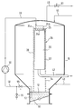
- the figure shows a filtration system with a liquid container 10.
- a filter element in the form of a filter candle 20 is arranged centrally within the liquid container 10.
- Several such filter candles 20 can be accommodated within the liquid container 10.
- the filter candle 20 is covered with a filter medium 22, for example a filter cloth.
- a suspension feed 40 opens into the bottom part of the liquid container 10.
- a bottom drain of the liquid container 10 is closed by a flap 50.
- a possible mode of operation is as follows: The suspension to be filtered is filled into the liquid container through the liquid feed 40 and pressurized. The pressure build-up can take place from the liquid supply line 40. Any trapped gas within the liquid container 10 can be discharged through a return line 45 in which a shutoff valve 51 is provided. After the liquid container 10 has been completely filled, the shutoff valve 51 is closed. As a result of the pressure built up in the liquid container 10, the liquid is pressed through the filter element 20 and collected in channels within the filter candle. This liquid is called the filtrate. It can flow off through a filtrate drain 42. Solid particles, which are contained in the suspension, collect in the form of a filter cake 26 on the surface of the filter medium 22. After the filtration process has ended, the filter cake can be removed by opening the flap 50.
- a circulating circuit 48, 30, 46 is started before the sinking liquid level has dropped below the upper end of the filter candle 20.
- This circulation circuit comprises a discharge line 48, which ends open at the deepest point of the liquid container 10, namely at point 52.
- This exhaust line 48 leads to a circulation pump 30, and a re-introduction line 46 leads from the circulation pump 30 to a location above the filter candle 20.
- a distributor device 24 is arranged, which is formed by a toothed crown 24a and a pitot tube 24b.
- Pitot tube 24b ends a short distance above of the bottom 24c of the serrated crown 24a, so that there is a narrow gap between the lower edge of the pitot tube 24b and the bottom 24c of the serrated crown 24a.
- the returned suspension liquid enters the upper end of the pitot tube 24b and passes through the gap to the wall of the crown 24a so that the liquid exits through the valleys of the crown 24a.
- the outer circumferential surface of the zigzag crown 24a is approximately flush with the outer surface of the filter candle 20.
- the liquid emerging through the valleys of the zigzag crown runs over the surface of the filter medium 22 or over the surface of the filter cake formed on the filter medium 22 in the form of a closed film.
- the valleys of the serrated crown 24a are so closely spaced in the circumferential direction that a liquid film which is closed all around is formed at the lower end of the serrated crown 24a.
- This liquid film extends from the tooth crown 24a downward over the entire height of the filter candle 20, insofar as it protrudes from the respective liquid level within the liquid container 10, and then opens into the liquid level.
- the closed liquid film 28 extends to the lower end of the filter candle 20 and then falls down into the residual liquid in the form of a droplet curtain 54.
- a volume of pressurized gas above the liquid level is maintained within the liquid container 10. The pressurized gas acts on the liquid film and continuously presses parts of the liquid of the liquid film through the filter medium 22.
- the passage of liquid through the filter medium 22 on the path of the film 28 to the lower end of the filter candle 20 is, however, dimensioned in relation to the film thickness of the liquid film 28 such that a closed liquid film is still present at the lower end of the filter candle 20.
- pressurized gas is continuously introduced into the liquid container 10 through the line 44, so that an approximately constant pressure difference is maintained between the liquid film on the one hand and the inner channels of the filter candle 20 on the other hand.
- the filter cake is further built up on the surface of the filter medium 22. Since the discharge line 48 ends in the lowest region of the liquid container 10, practically all of the residual liquid can be filtered out of the suspension container in this way.
- a shut-off valve 55 located in the discharge line 48 can be shut off and compressed gas can be admitted into the discharge line 48 through a gas inlet valve 56, so that liquid residues from the discharge line 48 of the pump 30 and the re-introduction line 46 can also be driven out and filtered as a liquid film 28 by the filter candle 20.
- a washing liquid can be introduced into the suspension container 10, for example through the suspension supply line 40, which can be provided with a corresponding multi-way valve (not shown).
- washing liquid can be continuously circulated through line 48, pump 30 and line 46 and a washing liquid film can form on the surface of filter medium 22.
- the washing liquid is then also gradually pushed through the filter medium 22 under the effect of the gas pressure prevailing in the suspension container 10 and washes approximately valuable substances contained in the filter cake and / or in the filter medium, which then flow off through the line 42 can and if necessary can be treated separately.
- a drying of the filter cake 26 is finally possible by introducing optionally heated pressurized gas, for example through line 44.
- the filter cake 26 can be removed through the open bottom flap.
- the pump 30 can be put into operation so that liquid reaches the distributor device 24 via the line 48, the pump 30 and the line 46 and flows down as a liquid film 28 over the filter candle 20 . If pressurized gas is then simultaneously applied through line 44, the filtration process begins. With increasing liquid level in the liquid container 10, a part of the pressurized gas can be blown off through the line 45, so that again a constant pressure difference between the outside of the liquid film 28 and the inner channels of the filter candle 20 is maintained while the liquid level continues to rise.
- the liquid level reaches the upper limit of the liquid container 10
- the pressure then being able to be maintained either through the supply line 42 or the pressurized gas supply line 44.
- the liquid film 28 is dimensioned such that it remains closed until it flows into the respective liquid level and no gas breakthroughs can take place.
- the method according to the invention can also be used to form a precoat cake on the surface of the filter medium 22, and again in film mode.
- the precoat suspended in an auxiliary liquid is introduced through line 40 and passed onto filter candle 20 in film mode.
- the suspension to be filtered can be introduced into the liquid container 10 and filtered according to the methods described above.
- a particular advantage of the method and the device according to the invention is that the entire filter surface with the maximum possible differential pressure is available from the start of the suspension feed to the processing of the last suspension residue, so that the entire filtration cycle can be processed in the theoretically required time minimum.
- the residual emptying according to the film principle by circulating in the lines 48 and 46 is preferably started before the liquid level in the liquid container 10 has dropped below the upper end of the filter candle 20.
- a negative pressure can also be built up within filter cartridge 20, in particular via line 42.
- the filter cake can be washed when the filter container is almost empty. H. with small amounts of detergent.
- the distributor device 24 is preferably designed to be self-draining so that no liquid residue remains in the distributor device. For this purpose the peaks can be pulled down to the bottom 24 of the peaks.
- the distributor device can also be provided with internals which ensure an even distribution of liquid under different hydraulic loads.
Landscapes
- Chemical & Material Sciences (AREA)
- Chemical Kinetics & Catalysis (AREA)
- Filtration Of Liquid (AREA)
Applications Claiming Priority (2)
| Application Number | Priority Date | Filing Date | Title |
|---|---|---|---|
| DE4105659 | 1991-02-22 | ||
| DE4105659A DE4105659A1 (de) | 1991-02-22 | 1991-02-22 | Verfahren zum betrieb einer filtrationsanlage und filtrationsanlage zur durchfuehrung dieses verfahrens |
Publications (2)
| Publication Number | Publication Date |
|---|---|
| EP0500109A1 true EP0500109A1 (fr) | 1992-08-26 |
| EP0500109B1 EP0500109B1 (fr) | 1996-10-16 |
Family
ID=6425708
Family Applications (1)
| Application Number | Title | Priority Date | Filing Date |
|---|---|---|---|
| EP92102865A Expired - Lifetime EP0500109B1 (fr) | 1991-02-22 | 1992-02-20 | Procédé de fonctionnement d'une installation de filtration et installation de filtration pour la mise en oeuvre |
Country Status (2)
| Country | Link |
|---|---|
| EP (1) | EP0500109B1 (fr) |
| DE (2) | DE4105659A1 (fr) |
Cited By (3)
| Publication number | Priority date | Publication date | Assignee | Title |
|---|---|---|---|---|
| US5618443A (en) * | 1995-05-04 | 1997-04-08 | Ahlstrom Machinery Oy | Clarification of green liquor by falling film cross-flow filtration |
| US5620596A (en) * | 1993-11-02 | 1997-04-15 | Ahlstrom Machinery Oy | Falling film cross filtration apparatus |
| EP0715875A4 (fr) * | 1994-06-24 | 1997-11-19 | Sapporo Breweries | Systeme de recuperation de filtrats |
Citations (5)
| Publication number | Priority date | Publication date | Assignee | Title |
|---|---|---|---|---|
| US1951017A (en) * | 1933-07-20 | 1934-03-13 | Weyerhaeuser Timber Co | Method of treating chemical pulf |
| US3794164A (en) * | 1970-12-21 | 1974-02-26 | Beuer Bros Co | Hopper type separating and classifying device |
| EP0025628A2 (fr) * | 1979-09-12 | 1981-03-25 | NoeL, MARQUET & CIE société anonyme: | Filtre à liquides à nettoyage automatique de l'élément filtrant |
| EP0280063A1 (fr) * | 1987-02-03 | 1988-08-31 | DrM, Dr. Müller AG | Procédé et appareil pour améliorer la filtration du volume résiduel dans un filtre |
| DE3918267A1 (de) * | 1988-06-18 | 1990-12-06 | Krupp Koppers Gmbh | Druckfilter |
Family Cites Families (4)
| Publication number | Priority date | Publication date | Assignee | Title |
|---|---|---|---|---|
| DE821336C (de) * | 1950-05-14 | 1951-11-15 | Holstein & Kappert Maschf | Einrichtung zum Entleeren von Druckfiltern |
| GB786570A (en) * | 1955-01-26 | 1957-11-20 | Paterson Engineering Company L | Improved filter for liquids |
| DE3477996D1 (en) * | 1983-08-08 | 1989-06-08 | Mueller Drm Ag | Process and filtering apparatus |
| CH678399A5 (fr) * | 1989-06-09 | 1991-09-13 | Mueller Drm Ag |
-
1991
- 1991-02-22 DE DE4105659A patent/DE4105659A1/de not_active Ceased
-
1992
- 1992-02-20 EP EP92102865A patent/EP0500109B1/fr not_active Expired - Lifetime
- 1992-02-20 DE DE59207352T patent/DE59207352D1/de not_active Expired - Fee Related
Patent Citations (5)
| Publication number | Priority date | Publication date | Assignee | Title |
|---|---|---|---|---|
| US1951017A (en) * | 1933-07-20 | 1934-03-13 | Weyerhaeuser Timber Co | Method of treating chemical pulf |
| US3794164A (en) * | 1970-12-21 | 1974-02-26 | Beuer Bros Co | Hopper type separating and classifying device |
| EP0025628A2 (fr) * | 1979-09-12 | 1981-03-25 | NoeL, MARQUET & CIE société anonyme: | Filtre à liquides à nettoyage automatique de l'élément filtrant |
| EP0280063A1 (fr) * | 1987-02-03 | 1988-08-31 | DrM, Dr. Müller AG | Procédé et appareil pour améliorer la filtration du volume résiduel dans un filtre |
| DE3918267A1 (de) * | 1988-06-18 | 1990-12-06 | Krupp Koppers Gmbh | Druckfilter |
Cited By (3)
| Publication number | Priority date | Publication date | Assignee | Title |
|---|---|---|---|---|
| US5620596A (en) * | 1993-11-02 | 1997-04-15 | Ahlstrom Machinery Oy | Falling film cross filtration apparatus |
| EP0715875A4 (fr) * | 1994-06-24 | 1997-11-19 | Sapporo Breweries | Systeme de recuperation de filtrats |
| US5618443A (en) * | 1995-05-04 | 1997-04-08 | Ahlstrom Machinery Oy | Clarification of green liquor by falling film cross-flow filtration |
Also Published As
| Publication number | Publication date |
|---|---|
| EP0500109B1 (fr) | 1996-10-16 |
| DE4105659A1 (de) | 1992-08-27 |
| DE59207352D1 (de) | 1996-11-21 |
Similar Documents
| Publication | Publication Date | Title |
|---|---|---|
| EP0951327B1 (fr) | Dispositif pour filtrer des liquides en continu | |
| DE69107199T2 (de) | Gerät zum filtrieren von suspensionen und betriebsverfahren des gerätes. | |
| DE3102670C2 (fr) | ||
| DE69417374T2 (de) | Membranbioreaktor mit einem Gasliftsystem | |
| DE2848660A1 (de) | Filtriervorrichtung | |
| DE3532611A1 (de) | Verfahren und vorrichtung zur entfernung von tinte aus abfallpapier | |
| DE1611158C3 (de) | Filtereinrichtung | |
| EP0135208B1 (fr) | Procédé de séparation de levure de bouillons de culture et application de ce procédé | |
| DE2229847A1 (de) | Verfahren und vorrichtung zum reinigen der filterbetten einer filtervorrichtung mit mehreren filtereinheiten | |
| DE1947538B2 (de) | Vorrichtung zur wasseraufbereitung in einem druckwind-schaltkessel | |
| DE1410811B1 (de) | Verfahren und Vorrichtung zum Reinigen von in einer Chemisch-Reinigungsmaschine anfallendem,schmutzversetztem Loesungsmittel | |
| EP0500109B1 (fr) | Procédé de fonctionnement d'une installation de filtration et installation de filtration pour la mise en oeuvre | |
| DE1943999B2 (de) | Vorrichtung zum filtrieren einer fluessigkeit | |
| DE69103602T3 (de) | Verfahren und vorrichtung zum trennen einer fasersuspension. | |
| EP3165596B1 (fr) | Procede de nettoyage de biere et nettoyeur de biere | |
| DE102009018934B4 (de) | Druckfiltervorrichtung und Verfahren zur Filtration | |
| DE69407661T2 (de) | Verbesserungen bei oder in Bezug auf Filtriervorrichtungen für Flüssigkeitsklärung, insbesondere Wasser | |
| DE2541147C3 (de) | Vorrichtung zum Eindicken von Trüben | |
| DE2920869C2 (fr) | ||
| DE3107899C2 (fr) | ||
| DE3432377C2 (fr) | ||
| DE60110163T2 (de) | Verfahren und Vorrichtung zum Rückspülen von Sandfilterbetteinheiten | |
| DE1935994A1 (de) | Verfahren zum Aufbringen einer Filterhilfsschicht auf das Filter von Filterpressen | |
| EP0305606B1 (fr) | Dispositif de filtration à nettoyage par contre-courant | |
| EP1000647B1 (fr) | Filtre à bougie pour la filtration à précouche de boissons |
Legal Events
| Date | Code | Title | Description |
|---|---|---|---|
| PUAI | Public reference made under article 153(3) epc to a published international application that has entered the european phase |
Free format text: ORIGINAL CODE: 0009012 |
|
| AK | Designated contracting states |
Kind code of ref document: A1 Designated state(s): CH DE FR IT LI NL |
|
| 17P | Request for examination filed |
Effective date: 19930107 |
|
| 17Q | First examination report despatched |
Effective date: 19940420 |
|
| GRAH | Despatch of communication of intention to grant a patent |
Free format text: ORIGINAL CODE: EPIDOS IGRA |
|
| GRAH | Despatch of communication of intention to grant a patent |
Free format text: ORIGINAL CODE: EPIDOS IGRA |
|
| GRAA | (expected) grant |
Free format text: ORIGINAL CODE: 0009210 |
|
| AK | Designated contracting states |
Kind code of ref document: B1 Designated state(s): CH DE FR IT LI NL |
|
| ITF | It: translation for a ep patent filed | ||
| REG | Reference to a national code |
Ref country code: CH Ref legal event code: NV Representative=s name: E. BLUM & CO. PATENTANWAELTE |
|
| REF | Corresponds to: |
Ref document number: 59207352 Country of ref document: DE Date of ref document: 19961121 |
|
| ET | Fr: translation filed | ||
| PLBI | Opposition filed |
Free format text: ORIGINAL CODE: 0009260 |
|
| PLBF | Reply of patent proprietor to notice(s) of opposition |
Free format text: ORIGINAL CODE: EPIDOS OBSO |
|
| 26 | Opposition filed |
Opponent name: DRM, DR. MUELLER AG Effective date: 19970710 |
|
| NLR1 | Nl: opposition has been filed with the epo |
Opponent name: DRM, DR. MUELLER AG |
|
| PLBF | Reply of patent proprietor to notice(s) of opposition |
Free format text: ORIGINAL CODE: EPIDOS OBSO |
|
| PLBF | Reply of patent proprietor to notice(s) of opposition |
Free format text: ORIGINAL CODE: EPIDOS OBSO |
|
| PLBO | Opposition rejected |
Free format text: ORIGINAL CODE: EPIDOS REJO |
|
| PLBN | Opposition rejected |
Free format text: ORIGINAL CODE: 0009273 |
|
| STAA | Information on the status of an ep patent application or granted ep patent |
Free format text: STATUS: OPPOSITION REJECTED |
|
| 27O | Opposition rejected |
Effective date: 19980515 |
|
| NLR2 | Nl: decision of opposition | ||
| PGFP | Annual fee paid to national office [announced via postgrant information from national office to epo] |
Ref country code: NL Payment date: 19990228 Year of fee payment: 8 |
|
| PGFP | Annual fee paid to national office [announced via postgrant information from national office to epo] |
Ref country code: FR Payment date: 19990301 Year of fee payment: 8 |
|
| REG | Reference to a national code |
Ref country code: CH Ref legal event code: PUE Owner name: SKW TROSTBERG AKTIENGESELLSCHAFT TRANSFER- BHS-SON Ref country code: CH Ref legal event code: PFA Free format text: BHS-BAYERISCHE BERG-, HUETTEN- UND SALZWERKE AKTIENGESELLSCHAFT TRANSFER- SKW TROSTBERG AKTIENGESELLSCHAFT |
|
| PG25 | Lapsed in a contracting state [announced via postgrant information from national office to epo] |
Ref country code: NL Free format text: LAPSE BECAUSE OF NON-PAYMENT OF DUE FEES Effective date: 20000901 |
|
| PG25 | Lapsed in a contracting state [announced via postgrant information from national office to epo] |
Ref country code: FR Free format text: LAPSE BECAUSE OF NON-PAYMENT OF DUE FEES Effective date: 20001031 |
|
| NLV4 | Nl: lapsed or anulled due to non-payment of the annual fee |
Effective date: 20000901 |
|
| REG | Reference to a national code |
Ref country code: FR Ref legal event code: ST |
|
| PGFP | Annual fee paid to national office [announced via postgrant information from national office to epo] |
Ref country code: DE Payment date: 20020131 Year of fee payment: 11 |
|
| PGFP | Annual fee paid to national office [announced via postgrant information from national office to epo] |
Ref country code: CH Payment date: 20020211 Year of fee payment: 11 |
|
| PG25 | Lapsed in a contracting state [announced via postgrant information from national office to epo] |
Ref country code: LI Free format text: LAPSE BECAUSE OF NON-PAYMENT OF DUE FEES Effective date: 20030228 Ref country code: CH Free format text: LAPSE BECAUSE OF NON-PAYMENT OF DUE FEES Effective date: 20030228 |
|
| PG25 | Lapsed in a contracting state [announced via postgrant information from national office to epo] |
Ref country code: DE Free format text: LAPSE BECAUSE OF NON-PAYMENT OF DUE FEES Effective date: 20030902 |
|
| REG | Reference to a national code |
Ref country code: CH Ref legal event code: PL |
|
| PG25 | Lapsed in a contracting state [announced via postgrant information from national office to epo] |
Ref country code: IT Free format text: LAPSE BECAUSE OF NON-PAYMENT OF DUE FEES;WARNING: LAPSES OF ITALIAN PATENTS WITH EFFECTIVE DATE BEFORE 2007 MAY HAVE OCCURRED AT ANY TIME BEFORE 2007. THE CORRECT EFFECTIVE DATE MAY BE DIFFERENT FROM THE ONE RECORDED. Effective date: 20050220 |