EP0500302A2 - Automatische Kontrolle für eine Vielzahl von Rauchartikeln - Google Patents
Automatische Kontrolle für eine Vielzahl von Rauchartikeln Download PDFInfo
- Publication number
- EP0500302A2 EP0500302A2 EP92301289A EP92301289A EP0500302A2 EP 0500302 A2 EP0500302 A2 EP 0500302A2 EP 92301289 A EP92301289 A EP 92301289A EP 92301289 A EP92301289 A EP 92301289A EP 0500302 A2 EP0500302 A2 EP 0500302A2
- Authority
- EP
- European Patent Office
- Prior art keywords
- smoking article
- measuring
- component
- gripping
- smoking
- Prior art date
- Legal status (The legal status is an assumption and is not a legal conclusion. Google has not performed a legal analysis and makes no representation as to the accuracy of the status listed.)
- Withdrawn
Links
Images


Classifications
-
- A—HUMAN NECESSITIES
- A24—TOBACCO; CIGARS; CIGARETTES; SIMULATED SMOKING DEVICES; SMOKERS' REQUISITES
- A24C—MACHINES FOR MAKING CIGARS OR CIGARETTES
- A24C5/00—Making cigarettes; Making tipping materials for, or attaching filters or mouthpieces to, cigars or cigarettes
- A24C5/32—Separating, ordering, counting or examining cigarettes; Regulating the feeding of tobacco according to rod or cigarette condition
-
- A—HUMAN NECESSITIES
- A24—TOBACCO; CIGARS; CIGARETTES; SIMULATED SMOKING DEVICES; SMOKERS' REQUISITES
- A24C—MACHINES FOR MAKING CIGARS OR CIGARETTES
- A24C5/00—Making cigarettes; Making tipping materials for, or attaching filters or mouthpieces to, cigars or cigarettes
- A24C5/32—Separating, ordering, counting or examining cigarettes; Regulating the feeding of tobacco according to rod or cigarette condition
- A24C5/34—Examining cigarettes or the rod, e.g. for regulating the feeding of tobacco; Removing defective cigarettes
-
- Y—GENERAL TAGGING OF NEW TECHNOLOGICAL DEVELOPMENTS; GENERAL TAGGING OF CROSS-SECTIONAL TECHNOLOGIES SPANNING OVER SEVERAL SECTIONS OF THE IPC; TECHNICAL SUBJECTS COVERED BY FORMER USPC CROSS-REFERENCE ART COLLECTIONS [XRACs] AND DIGESTS
- Y10—TECHNICAL SUBJECTS COVERED BY FORMER USPC
- Y10S—TECHNICAL SUBJECTS COVERED BY FORMER USPC CROSS-REFERENCE ART COLLECTIONS [XRACs] AND DIGESTS
- Y10S131/00—Tobacco
- Y10S131/908—Sensing unique characteristic or specific condition of finished product
-
- Y—GENERAL TAGGING OF NEW TECHNOLOGICAL DEVELOPMENTS; GENERAL TAGGING OF CROSS-SECTIONAL TECHNOLOGIES SPANNING OVER SEVERAL SECTIONS OF THE IPC; TECHNICAL SUBJECTS COVERED BY FORMER USPC CROSS-REFERENCE ART COLLECTIONS [XRACs] AND DIGESTS
- Y10—TECHNICAL SUBJECTS COVERED BY FORMER USPC
- Y10S—TECHNICAL SUBJECTS COVERED BY FORMER USPC CROSS-REFERENCE ART COLLECTIONS [XRACs] AND DIGESTS
- Y10S83/00—Cutting
- Y10S83/929—Particular nature of work or product
- Y10S83/931—Tobacco
Definitions
- This invention relates to an automatic test station for handling bundles of smoking articles and performing one or more of a plurality of physical measurements on individual smoking articles and components thereof. More particularly, this invention relates to an automatic test station having a plurality of measuring stations and a robotic device for maneuvering differently dimensioned smoking articles to one or more of the measuring stations in a preselected sequence in an unattended mode.
- a plurality of like smoking articles are subjected to tests that measure one or more of those specific properties.
- the test results may be used to evaluate the uniformity of the measured property or properties from article to article within the plurality of like articles and to obtain statistical data regarding the characteristics of the like articles in that plurality of articles.
- multiple pluralities of like articles wherein the articles in each plurality may be different, are typically subjected to the same series of tests under conditions that permit comparing the statistical characteristics of the different like articles.
- Tests may be performed both on the complete article and separately on components of a complete article.
- the filter portion of a filter-tipped smoking article may be measured for pressure drop, circumference and size. This requires that the filter be severed from the smoking article. Any tobacco shreds that remain affixed to the filter are removed from the filter portion.
- test insert ents are arranged in a work area.
- An operator manually places each smoking article, or its component, into each instrument and actuates the insert ent to conduct the desired measurement.
- the test result i.e., the measured parameter is then displayed on the insert ent and the data are typically transmitted to a host computer for recordation in a database.
- the database is used for subsequent analysis and tabulation.
- the operator must manually sever the component from the article, dispose of the remainder of the article (or save it for subsequent testing), and then insert the component into the proper instrument or instruments to acquire the desired measurements.
- the filter rod is typically severed from the cigarette using a razor blade to cut through the tobacco portion, and any tobacco shreds remaining attached to the filter are removed by the operator using a small instrument or a finger.
- the cleaned or deshredded filter is then inserted into the measuring insert ents and the data acquired.
- Tests on manually guided articles also may be subject to variations in how or where the smoking article is gripped and/or positioned during the measurement procedure. These variations are undesirable for obtaining accurate statistical data.
- Fidus-Instrument Corporation has available a product line under the trade name Automatic Test Stations.
- the automatic test stations provide combinations of instruments for measuring one or more of weight, circumference/diameter, ventilation, pressure drop, and hardness.
- Model numbers CTS 500, CTS 400, CTS 350, and CTS 300 are automatic test stations for testing only cigarettes.
- Model numbers FTS 400 and FTS 300 are automatic test stations for testing only filter rod portions.
- the different numerical designations indicate that different combinations of instruments for performing various measurements are combined into a single CTS or FTS station.
- the measuring units are stacked on top of each other so that each article or filter rod to be tested is downwardly and sequentially indexed along an axis through the instruments.
- the automatic test stations are available in conjunction with a product under the trade name Automatic Hopper Loader, model number AHL 100, also available from Fidus Instrument Corp.
- the Automatic Hopper Loader device has a plurality of bins for receiving bundles of a plurality of smoking articles (or filter rods) that may be loaded with up to eighteen bundles of smoking articles (or filter rods) simultaneously.
- the commercial hopper device transfers the contents of one bin to a hopper area.
- the contents loaded in the hopper area are then fed, one at a time, into either a CTS or FTS device, to which the hopper is mated.
- the bins are then indexed to bring the next bin into position for unloading into the hopper.
- the CTS and FTS automatic test station devices are capable of providing the results of the acquired test data to a master computerfor tabulation and recordation.
- each model Automatic Test Station is configured with a sufficiently broad number of tests which are performed on each smoking article or filter rod fed into the Station. Thus, unnecessary tests are performed. Also, if one insert ent module in a station becomes inoperative, the entire station becomes inoperative until that module can be repaired or replaced.
- such robotic devices typically do not have the ability to grasp securely a preselected range of differently dimensioned smoking articles without deforming at least some articles in the range.
- the use of force transducers to monitor the forces exerted to control gripping of the article has been considered.
- such transducers increase the cost and complexity of the device.
- such transducers monitor force, they do not detect whether the deformable article is securely gripped and not deformed or damaged.
- Such force transducers are not likely to prevent the opposing members from damaging relatively fragile smoking articles.
- a computer-controlled robotic automatic test station that measures a selected number of a plurality of physical parameters of smoking articles and/or smoking article components in a selected sequence.
- One aspect of the present invention is directed to an apparatus for measuring a physical characteristic of a plurality of smoking articles.
- One such apparatus comprises:
- the controlling means is a microprocessor which controls the gripping and releasing means to release the one smoking article at the measuring means so that the physical characteristic can be measured and to grip the one smoking article at the measuring means following the measurement.
- the gripping and releasing means and the maneuvering means are a robot having a first member and a second member, the first and second members being movable in opposition for gripping therebetween a smoking article.
- the measuring means further comprises a first means for measuring a first physical characteristic of a smoking article located at the second location and a second means for measuring a second physical characteristic of a smoking article, the second measuring means being located at a third location within the range of motion, and wherein the controlling means controls the gripping and releasing means and the maneuvering means to grip the one smoking article at the first location and to maneuver the one smoking article to one of the first and second measuring means whereby one of the first and second physical characteristics can be measured.
- the controlling means preferably also controls the gripping and releasing means and the maneuvering means to maneuver the one smoking article from the one of the first and second measuring stations to the other of the first and second measuring means whereby the other of the first and second physical characteristics can be measured.
- the measuring means further comprises more than one means for measuring more than one selected physical characteristics of a smoking article wherein each said means is located at a different location within the range of motion and measures a different physical characteristic, said means being selected from among the group consisting of means for measuring circumference, means for measuring pressure drop and means for measuring length, and for filter-tipped smoking articles, means for measuring ventilation, and wherein the controlling means controls the gripping and releasing means and the maneuvering means to maneuver the one smoking article to one or more of the measuring means.
- the controlling means preferably further comprises a means for providing a test sequence identifying one or more physical characteristics of the one smoking article to be measured, wherein the controlling means is responsive to the test sequence and controls the gripping and releasing means and the maneuvering means to maneuver the gripped one smoking article to one or more of the measuring means so that the one or more identified physical characteristics can be measured.
- the test sequence identifies the order in which the measurements of the one smoking article are to be made, and more preferably the order in which the measurements of each smoking article in the plurality of smoking articles are to be made.
- Another aspect of the present invention is directed toward an apparatus for measuring a physical characteristic of a component of a plurality of smoking articles.
- One such apparatus includes:
- the controlling means is a microprocessor which controls the gripping and releasing means to grip the one smoking article by its component, release the one smoking article component at the measuring means so that the physical characteristic of the one smoking article component can be measured, and grip the one smoking article component at the first measuring means following the measurement.
- the gripping and releasing means and the maneuvering means are a robot having a first member and a second member, the first and second members being movable in opposition for gripping therebetween a smoking article.
- the measuring means comprises a first measuring means for measuring a first physical characteristic of a smoking article component located at the third location and a second means for measuring a second physical characteristic of a smoking article component, the second measuring means being located at a fourth location within the range of motion, and wherein the controlling means controls the gripping and releasing means and the maneuvering means to grip and maneuver the one smoking article component to one of the first and second measuring means whereby one of the first and second physical characteristics can be measured.
- the controlling means preferably controls the gripping and releasing means and the maneuvering means to maneuver the one smoking article component from the one of the first and second measuring stations to the other of the first and second measuring means whereby the other of the first and second physical characteristics of the smoking article component can be measured.
- the first and second measuring means are preferably selected from among the group consisting of means for measuring ventilation, means for measuring pressure drop, and means for measuring length.
- the measuring means further comprises a first means for measuring a first physical characteristic of a smoking article component and a second means for measuring a second physical characteristic of a smoking article, the second measuring means being at a fourth location within the range of motion, wherein the controlling means controls the gripping and releasing means and the maneuvering means to grip the one smoking article at the first location, to maneuver the one smoking article to the second measuring means so that the first physical characteristic of the one smoking article can be measured, and then to the severing means, thereby to sever the component, and to maneuver the one smoking article component to the first measuring means so that the first physical characteristic of the one smoking article component can be measured.
- the first measuring means further comprises more than one means for measuring more than one physical characteristic of a smoking article component at more than one location in the range of motion
- the second measuring means further comprises more than one means for measuring more than one physical characteristic of a smoking article located at more than one location in the range of motion
- the controlling means further comprises a means for providing a test sequence identifying one or more physical characteristics of the one smoking article and one or more physical characteristics of the one smoking article component to be measured, wherein the controlling means is responsive to the provided test sequence and controls the gripping and releasing means and the maneuvering means to maneuver the gripped one smoking article to one or more of the second measuring means, and the severing means, and one or more of the first measuring means so that the one or more identified physical characteristics of the smoking article and the smoking article component can be measured.
- the test sequence may identify the order in which the measurements of the one smoking article component are to be made and more preferably the order in which the measurements of each smoking article component of the plurality of smoking article are to be made.
- the physical characteristics of a smoking article are obtained prior to the physical characteristics of a smoking article component.
- the apparatus includes a second means for receiving a smoking article at a fifth location within the range of motion wherein the microprocessor means controls the gripping and releasing means and the maneuvering means to release the one smoking article onto the second receiving means and then to grip the smoking article by its component on the second receiving means, to maneuver the one smoking article to the severing means, and to grip the one smoking article component during the severing process.
- each smoking article component is a filter rod of a cigarette and the apparatus further comprises a means for deshredding the severed filter component of a cigarette, wherein the microprocessor means controls the gripping and releasing means and the maneuvering means to maneuver a severed filter to the deshredding means following the severing operation.
- Another aspect of the present invention is directed toward a method for measuring a physical characteristic of a plurality of smoking articles at a test station having a means for gripping and releasing a smoking article, means for maneuvering a gripped smoking article within a range of motion, means for receiving one of said plurality of smoking articles at a first location within the range of motion, means for measuring a physical characteristic of a smoking article, the measuring means being at a second location within the range of motion; and microprocessor means for controlling the gripping and releasing means and the maneuvering means.
- One such method comprises the steps of providing a plurality of smoking articles;
- the method includes releasing the one smoking article at the measuring meals so that the physical characteristic can be measured aid gripping the one smoking article at the first measuring meals following the measurement.
- the gripping aid releasing meals aid the maneuvering meals are a robot having a first member aid a second member movable in opposition, and gripping aid releasing the one smoking article further comprises moving the first aid second members together for gripping a smoking article and moving the first and second members apart to release the smoking article.
- test station includes more than one means for measuring more than one selected physical characteristics of a smoking article and each said means is located at a different location within the range of motion, said means being selected from among the group consisting of means for measuring circumference, means for measuring pressure drop and means for measuring length, the method further comprises the steps of:
- Another aspect of the present invention is directed towards a method for measuring a physical characteristic of a component of a plurality of smoking articles in a test station having means for gripping and releasing a smoking article, means for maneuvering a gripped smoking article within a range of motion, means for receiving one of said plurality of smoking articles at a first location within the range of motion, means for severing the component of a smoking article from the smoking article, the severing means being located at a second location within the range of motion, means for measuring a physical characteristic of a smoking article component, the measuring means being at a third location within the range of motion, and microprocessor means for controlling the gripping and releasing means and the maneuvering means.
- One such method comprises:
- the method further comprises releasing the smoking article component at the measuring means so that the physical characteristic of the one smoking article component can be measured and gripping the one smoking article component at the measuring means following the measurement.
- the gripping and releasing means and the maneuvering means are a robot having a first member and a second members movable in opposition and the step of gripping the one smoking article or one smoking article component further comprises moving the first and second members together and the step of releasing the one smoking article component further comprises moving the first and second members apart.
- the measuring means further comprises one or more means for measuring one or more physical characteristics of a smoking article component selected from among the group consisting of means for measuring ventilation, means for measuring pressure drop and means for measuring length, and one or more means for measuring one or more physical characteristics of a smoking article, each measuring means being located at a different location within the range of motion, wherein the method further comprises:
- providing the test sequence further comprises identifying the order in which the measurements of the one smoking article and the one smoking article component are to be made, and more preferably the order in which the measurements of each smoking article and smoking article component of the plurality of smoking articles are to be made.
- test station includes a second means for receiving a smoking article at a fourth location within the range of motion and the step of maneuvering the gripped one smoking article to the severing means further comprises:
- the smoking article and its component further comprise a tobacco-containing cigarette and a filter tip and the method further comprises:
- the invention concerns providing a robot, a system microprocessor controller, a selected number of misting laboratory measuring instruments, and a smoking article severing station.
- the microprocessor device controls the robot, instruments, and severing station so that each article or component to be tested is maneuvered through a predetermined sequence of tests.
- a hopper feeder device may be provided so that several sets of samples can be loaded at one time into separate bins in that device whereby each sample set is identified with a code and the physical parameters of the samples in each set are enumerated and assigned to that code.
- the sequence of the tests to be run on the samples in the set and which tests are to be run on which samples are established in a database that is associated with the code.
- the code is read and the appropriate database parameters are incorporated into the instructions to the robot so that samples are properly maneuvered into the proper position for conducting the selected measurements to be performed in the selected sequence.
- the system controller instructs the hopper-feeder to unload one hopper-bin containing a sample set into a feeder device and to feed one article from that set at a time.
- the system controller reads the code associated with that bin and sample set and adjusts the instructions to be delivered to the robot to account for the parameters of the samples to be measured and the tests sequence to be conducted.
- the system controller then instructs the robot to grip an article and place it into the selected test instruments in the selected sequence, to obtain the test results and data, optionally to print the data, and preferably to transmit the acquired data to a host computer for further processing.
- the system controller counts the number of samples processed and advances the hopper feeder to unload another sample set for the next test sequence.
- a flexible automatic test station which can increase overall productivity by allowing the system operator to perform other duties or tests that are not susceptible to robotic controlled performance while the test station is processing multiple sample sets. These duties also could include reviewing test data and loading additional sample sets into the station.
- a station in accordance with the present invention can be operated in an unattended mode, and thus can conduct tests after regular work hours to accommodate peak work loads without requiring training of additional operators to conduct the tests manually.
- those instruments can be manually used when the automatic feature of the test station is not being used.
- Another advantage to the flexible test station of the present invention is that it can be modified as needed by the addition or deletion of various measuring instruments (modified for remote microprocessor control). Yet another advantage is that if one instrument becomes inoperative, the test station may stop operation and alert an attending operator or, if unattended, skip the inoperative instrument and continue to perform the other tests on the samples in the sample sets.
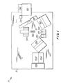
- station 10 in accordance with a preferred embodiment of the invention includes table 12, robot 503, hopper-feeder 100, station 200 for measuring the length of an article, circumference station 600 for measuring the circumference of the smoking article, PDI station 700 for measuring the smoking article pressure drop and filter ventilation, fixture 900 for reorienting a smoking article, severing station 300 for severing an article component from the article, deshredding station 400 for removing tobacco shreds film the severed component, PDI 800 for measuring the filter pressure drop, station 850 for measuring the length of a filter, and microprocessor 1000 for controlling the operation of station 10.
- host coomputer 1200 for containing test protocols and paramaters in a database listing and acquiring test data for for tabulation, evaluation and analysis. Additionally, station 10 includes operator workstation 10.
- Table 12 is preferably a flat table for supporting the various devices, insert instruments, and processing stations at positions within the reach of robot 503.
- Table 12 is sufficiently large, e.g., 1.5m by 2m (five feet by seven feet), to restrict an operator from interfering with the motion of robot 503 and either injuring the operator or halting the motion of the robot.
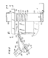
- hopper feeder 100 has a plurality of pockets 110 attached to a continuous belt 120 that travels around sprockets 122.
- belt 120 is indexed to advance the plurality of pockets 110 a distance corresponding to the spacing between each pocket.
- each pocket 110 is capable of containing a sample set of a plurality of smoking articles 20, for example, up to thirty articles, preferably of the same type or brand.
- Each pocket 110 will typically contain a sample set of a plurality of like articles 20 that may be the same or different from each sample sets in other pockets.
- An unloading device 130 is positioned at a selected location relative to the path of belt 120 so that as one of pockets 110 is indexed into alignment with device 130, the contents of the one pocket are transferred from that pocket into device 130.
- Unloading device 130 may be a paddle or flange that pushes the articles out of pocket 110 or alternatively manipulates pocket 110 to release its contents. Referring to FIG. 2, device 130 moves from an extreme left position to an extreme right position in a range of travel. One pocket 110 is indexed into alignment with device 130, which is then moved from its extreme right position to its extreme left position, thereby pushing articles 20 out of the one pocket 110 and into a feed mechanism 140.
- Feed mechanism 140 dispenses the articles in device 130 one at a time into chute 220.
- One such feed mechanism 140 may be, for example, a V shaped feed structure 150 having an aperture 152 at the vertex so that articles 20 are fed through the vertex aperture one at a time, and a device for receiving one article at a time for transferring that article to chute 220 (not shown).
- the plurality of articles 20 in pockets 110 are longitudinally aligned with chute 220 so that no angular manipulation is required.
- Hopper feeder 100, unloading device 130, and feed mechanism 140 are preferably a commercial device, for example, model AHL 100, purchased from Fidus Instrument Corporation.
- the commercial device is constructed with a funnel type feed mechanism for feeding the contents that are unloaded from a pocket one at a time, in a vertical direction downwardly, to an interconnected commercial CTS or FTS test station.
- the conventional funnel mechanism was removed and the commercial hopper feeder device was installed at one edge of table 12 proximate to chute 220 so that chute 220 receives at an angle each article 20 as it is fed out the feed mechanism provided with the commercial device. Thus, each article 20 slides down chute 220 at an angle to horizontal.
- the commercial device also was modified by the addition of feet (not shown) so that it would stand on the floor.
- Hopper system 100 as purchased contained motor drive electronics and controls that connected directly to a computer. This required that the computer send a pulse to the stepping motor each time belt 120 was moved, requiring 16,000 pulses to index from one pocket 110 to the next.
- a commercial preset indexer was added (not shown). This device is programmed to generate the required number of pulses when computer 1000 toggles a digital input on the indexer. The indexer is capable of generating the control signals for device 130, thus offloading control computer 1000.
- the digital input on the present indexer can also be toggled using a pushbotton, allowing manual control of the system 100.
- This manual control may be used for set-up and adjustments to system 100 and for troubleshooting, all without use of computer 1000.
- the as purchased control of feed mechanism 140 likewise required computer control to monitor the index detector, to determine when to stop the motor driving device 140.
- Hopper system 100 was similarly modified to work independently, turning the feed mechanism one revolution and stopping automatically whenever a digital input is toggled to start the motor rotation.
- robot 503 includes base 590, rotating platform 591, pivoting member 592, pivoting arm 593, hand 500, and opposing members 510 and 520.
- Base 590 provides base rotation in the horizontal plane of robot 503 about an axis and is secured to table 12.
- Pivoting member 592 provides for shoulder joint movement by rotating in a two dimensional vertical plane.
- Pivoting member 593 provides for elbow joint movement by rotation in a two dimensional vertical plane.
- Hand 500 provides a wrist pitch motion and wrist rotation motion in three dimensions.
- Hand 500 includes means for translating a pair of opposing members 510 and 520 for gripping one smoking article 20 toward and away from each other so that the opposing members contact and grip article 20 securely without deforming article 20.
- Robot 503 preferably has five independently controlled axes with position repeatability of +/- 0.5 mm, and a maximum reach in the range of from about 600mm to 700mm (24 to 27 inches).
- Robot 503 is controlled by microprocessor 1000 and is thus capable of operating unattended and repeatedly performing each of the possible sequences or processes with the same accuracy and precision. Because it is a software controlled device, robot 503 can be controlled by appropriate programming to perform a sequence of motions which may be the same or different for each article that is gripped and maneuvered as described below.
- Robot 503 is preferably a model Movemaster 11, manufactured by Mitsubishi, Inc., of Japan, and available from Perkin-Elmer Corporation as part of a product known as the MasterLab t m System.
- the MasterLab t m device includes as microprocessor 1000 an IBM PC computer, model AT, having an Intel 8088 microprocessor device, 286 kilobyte memory, and software appropriate to control the initialization and motion of robot 503 relative to base 590 in the five dimensions and, thus, relative to each of the stations with which robot 503 interacts as described herein.
- the software for controlling the motion of the robot uses the commercial known programming language PERL (Perkin-Elmer Robot Language), which is a menu driven language having a dedicated command structure.
- PERL Perkin-Elmer Robot Language
- Microprocessor 1000 also is provided with appropriate and conventional data communication ports to control the various test instruments to perform the desired measurements when the smoking article or the filter portion or other component is inserted into the measuring station, and to receive test data obtained.
- Appended hereto as a software appendix is a software listing for operation of robot 503 of automatic test station 10 in accordance with the present invention.
- First member 510 is secured to flange 501 and support member 560 (and hence member 520) is secured to corresponding flange 502 so that members 510 and 520 are generally disposed in relatively fixed angular orientations, e.g., in parallel, and have opposing respective inner surfaces 511 and 521.
- Force altering means 570 is connected to support member 560 and second member 520.
- It provides for moving member 520 relative to support 560 to alter or adjust the force exerted on gripped smoking article 20, thereby to maintain the force below the force that would otherwise be imposed on smoking article 20 if there was no such movement, and below a selected maximum force that might crush or deform article 20.
- force altering means 570 includes lever 530, spring 540, stop 550, and pin 563.
- Lever 530 is secured at one end to member 520 by bolt 531.
- Spring 540 is set within receptacle 541 milled in support 560 and urged against lever 530.
- Member 520 is pivotally secured to support 560 between yokes 561 and 562 about pin 563.
- Stop 550 is adjustably secured to support 560 so that it extends a selected distance from support 560.
- Stop 550 includes a flange 551 that is configured to fit over end 533 of lever 530. Spring 540 thus urges lever 530 against stop 550 flange 551.
- the range of motion of lever 530, and hence member 520, is limited by the motion of lever end 533 between support 560 and stop 550 as lever 530 pivots about pin 563.
- the position of stop 550 is adjustable to control the range of motion and is typically set so that member 520 is normally biased parallel to member 510 when not in contact with any article 20. Stop 550 also is used to keep member 520 from over-extending towards member 510 due to the force that spring 540 exerts on lever 530.
- stop 550 could be adjusted so that tip 522 is biased closer to tip 512 than yokes 561 and 562 are spaced to member 510. This provides for gripping a slightly greater range of differently dimensioned articles as compared to when members 510 and 520 are biased parallel, but makes positioning members 510 and 520 about each article more difficult, requiring a comparatively larger distance between members 510 and 520 in the open position.
- member 570 could be adjusted so that some of the force that would otherwise be exerted by members 510 and 520 on article 20 is altered when each article in this preselected range of differently dimensioned articles is gripped.
- Member 520 has a notch 525 cut in surface 521 near tip 522 and member 510 has a corresponding notch 515 cut in opposing surface 511 near its tip 512.
- Notches 515 and 525 are thus in opposition for gripping a smoking article 20 therebetween.
- Notches 515 and 525 each preferably comprises two planar surfaces that intersect at an angle a of approximately 90 degrees. Further, the notches are arranged to form a receptacle for receiving and supporting article 20.
- notches 515 and 525 are chosen so that a preselected range of dimensions of differently dimensioned smoking articles 20 can be supported and securely gripped by opposing forces exerted by members 510 and 520. Differently dimensioned articles thus may have different contact points on the respective planar surfaces. Futhermore, notches 515 and 525 are configured so that each smoking article is held rigidly in place along four contact points between members 510 and 520 and does not "slip" axially or longitudinally while it is being maneuvered from station to station or held in place at a station. Other angles and contoured shapes for notches 515 and 525 may be used.
- the gripping surfaces of notches 515 and 525 are lined with conventional emery paper, for example, 240 grade, or some other mildly abrasive material to increase the friction between smoking article 20 and members 510 and 520 and to minimize slip.
- conventional emery paper for example, 240 grade, or some other mildly abrasive material to increase the friction between smoking article 20 and members 510 and 520 and to minimize slip.
- flanges 501 and 502 are translated to an "open" position spaced apart a first distance and hand 500 is maneuvered to position notches 515 and 525 on opposite sides of and in alignment with a selected smoking article 20.
- Article 20 may be resting on chute 220, reorientation fixture 900, or on any one of the measuring insert ents having a suitable receptacle.
- the first distance is large enough to straddle the largest circumference smoking article in the preselected range of circumferences.
- microprocessor 1000 instructs robot 503 to "close" flanges 501 and 502 so that member 510 and support member 560 are translated together and spaced a second distance apart and notches 515 and 525 are in gripping contact with the smoking article.
- member 510 and support 560 are maintained in a parallel orientation.
- the second distance and the dimensions and depth of notches 515 and 525 are selected so that in the closed position, notches 515 and 525 will grip securely without deformation the smallest and largest dimensioned smoking articles in the preselected range of articles.
- spring 540 biases lever 530 against stop 550 so that member 520 is urged parallel to member 510.
- members 510 and 520 are configured and spaced to grip securely the article in notches 515 and 525 whereby member 520 does not significantly move relative to support 560.
- the larger dimension will move member 520 to pivot away from member 510 and compress spring 540.
- Spring 540 will continue to bias member 520 toward member 510 to group securely article 20, even though the second distance is such that the larger dimensioned article would have been crushed in notches 515 and 525 had member 520 not pivoted relative to support 560. In this manner, spring 540 alters or adjusts the force exerted on article 20 so that article 20 is not crushed.
- force altering means 570 permits members 510 and 520 to grip securely a wider variation of smoking article dimensions, specifically circumferences, than would be possible by members 510 and 520 that did not have a force altering means.
- These improvements in gripping range and performance are important for use in a robotic automated test station where different dimensions present substantial problems, in contrast to a manually conducted system where the operator can intuitively adjust his or her grip to the dimension of the article.
- a plurality of smoking articles to be tested do not inherently have identical physical characteristics. For example, there may be a variation in smoking article circumference from article to article in the same sample set or from one group of article to another.
- multiple sample sets may have differently dimensioned like articles.
- a gripping mechanism for a robotic device in accordance with the present invention is thus able to accommodate the desired variations in dimensions so that the resulting testing data of multiple sets is automatic, reliable, and reproducible without an attendant or need to adjust or change the opposing gripping members.
- a pair of gripping members 510 and 520 has been constructed and operated successfully for grasping smoking articles having a circumference dimension selected in the range of from 22 to 25 mm.
- members 510 and 520 were constructed with mirror image tip portions each having a width d of about 14mm (0.56 inches) and a thickness t of about 7mm (0.28 inches).
- Notches 515 and 525 each has two planar sides cut at 45° angles to the surface, thereby forming an angle a of 90°, the vertex of which extends a depth h of about 4.37mm (0.172 inches) relative to member surfaces 511 and 512.
- the notch base of depth h is located a distance r of about 7mm (0.280 inches) from the tip of the member, and the opening of the notch has a space s of about 8. 76mm (0 345 inches).
- the distance between surfaces 511 and 521 was fixed at about 2. Omm, which was obtained by manually filing down a shim plate (not shown) to bring faces 511 and 521 sufficiently close together to obtain a good secure grip on the smallest dimensioned article to be processed, e.g. 22mm in circumference, without deflecting members 510 and 520.
- Member 520 is configured so that the base of notch 525 is spaced about 30mm (1.22 inches) from the axis of pin 563.
- the spring force of spring 540 is selected to be a few tens of grams (a few ounces), preferably 80 to 170g (three to six ounces).
- the optimum spring force for a given gripper design will be selected based upon the particular geometric distances employed in the design of lever 530, member 520, notches 525 and 515, the spacing between member 510 and 520, the range of motion of the hinge of member 520, and the selected range of differently dimensioned smoking articles to be tested.
- the magnitude of the spring force will depend in part on the distance of separation between pivot pin 563 and notches 525 and 515 and the distance of separation between pivot pin 563 and spring 540.
- opposing gripper members may be used, for example, a member which translates, as opposed to rotates, relative to a support, in combination with a force altering means which allows the member to move relative to the support.
- the force altering means can have non-linear characteristics in contrast to the typically linear characteristics of a conventional spring.
- robot 503 in accordance with the present invention, provides for an economical and efficient gripping of a variety of conventionally sized smoking articles having a circumference in a preselected range of circumference dimensions, including cigarettes, for efficient manipulation of such articles through a programmed sequence of movements and operations without having to change or adjust manually the robotic gripping elements for differently dimensioned articles in the range.
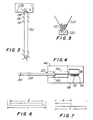
- Chute 220 is configured to receive one article 20 at top 221 of chute 220, and is provided with a grooved surface having a U-shaped cross sectional shape (see FIG. 5) so that article 20 will advance along chute to stop 222 under gravity.
- a surface also may be concave or V-shaped and may be coated with a low friction material, e.g., Teflon TM, or highly polished to minimize friction between article 20 and chute 220.
- Chute 220 also may comprise two rods or rails that are spaced-apart in parallel (not shown) so that articles 20 will proceed along chute 220 and any tobacco or other particles that come loose from articles 20 do not accumulate in chute 220 or otherwise impede the advance of articles 20.
- Camera 230 is mounted on bracket 240 to be positioned a selected distance from chute 220.
- Camera 230 is preferably an electronic linear array camera for measuring lengths along one axis or dimension. Accordingly, that measuring axis is oriented in parallel with chute 220 so that article 20 will be in the proper orientation for obtaining the length measure.
- Camera 230 is located a focal distance f from the location article 20 will be at when it is measured, and is provided with a field of view r corresponding to focal distance f.
- the measurement may be obtained directly by measuring article length L within the field of view r (see FIG. 6) or more preferably indirectly, by measuring the length a of article 20 that extends into the field of view from one edge of the field of view in the first axis (see FIG. 7).
- one edge of field of view r is located a known distance d from stop 222.
- camera 230 obtains the measure 1 of article 20 indirectly by summing the measured length a and the known distance d.
- camera 230 is configured so that distance d is 75 mm, field of view r is 50 mm, one end of which is spaced 75 mm from stop 222, the other end of which extends to 125 mm from stop 222, providing for a focal distance f selectable in the range of from 225 to 260 mm.
- camera 230 is capable of measuring automatically conventional cigarettes having a length from 75 to 125 mm.
- the measure must be converted by the magnification (or reduction) power of the camera lens to obtain the true length dimension.
- stop 222 may be provided with a contact switch (not shown) that produces directly or through microprocessor 1000 an enabling signal to camera 230 when article 20 comes to rest against stop 222.
- camera 230 will obtain the length measurement in response to the enabling signal.
- Camera 230 is preferably a model HVS 256 camera sold by the Microswitch Division of Honeywell, Engel- wood, Colorado and has a resolution of 256 pixels in a selected linear dimension or axis.
- Model HVS 256 is preferably configured to obtain a 50 mm field of view at an accuracy of better than 0.1 mm, preferably 0.05 mm, corresponding to a resolution of better than 0.1 mm, preferably 0.02mm. It is a relatively inexpensive linear array camera, and is thus advantageous to use to measure indirectly the article length.
- the first distance d the field of view r and the desired resolution may be adjusted to measure a desired range of acceptable lengths (and variations in lengths) of a large number of different smoking articles.
- camera 230 may be moved outwardly and refocused or a different lens used to have a correspondingly increased field of view, or the distance d may be changed as may be appropriate.
- Other linear array cameras having more pixels, e.g., an EG&G Reticon camera, model LC0120, having 4096 pixels and a resolution of 0.01 mm in one axis, or fewer pixels with a corresponding lower resolution could be used to obtain directly or indirectly the length measurement.
- linear array cameras having such a higher pixel resolution are, however, substantially more expensive.
- Electronic linear array cameras provide almost an instantaneous measure of indirect length a or direct length I depending on the desired configuration. Accordingly, continuous motion length measures are possible. Measures taken while the article is stationary for a period of 0.085 seconds are, however, preferred for optimum resolution.
- Camera 230 is preferably adapted to transmit electronically the measured length to microprocessor 1000, which may in turn transmit the data to host computer 1200 for recording and tabulating the data for each article 20 measured.
- robot 503 grips article 20 between members 510 and 520 at a distance that is about 65 mm from the filter end for maneuvering article 20 off chute 220 to the selected one or more workstations for subsequent measurements or tests of the characteristics of the smoking article. Accordingly, chute 220 and stop 222 are suitably located within the range of motion of robot 503 with adequate clearance relating to robot hand 500.
- Fixture 900 for reorienting a smoking article is located on table 12 at a position within reach of robot 503.
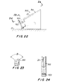
- Fixture 900 provides a location into which an article 20 (shown in phantom lines in FIG. 22) can be deposited by robot 503 so that robot 503 can change its grip on article 20 to a different location.
- Fixture 900 includes a v shaped, concave surface 910 having a length and two planar surfaces intersecting at an angle B of 110 degrees. Surface 910 is spaced from a stop 920 a distance D2 of about 31.7mm (1.25 inches) to allow members 510 and 520 of robot 503 to grip article 20 without contacting fixture 900.
- Stop 920 is preferably oriented perpendicular to surface 910 and includes a protrusion 925 which extends from stop 920 so that the end of article 20 is spaced a short distance from stop 920.
- Surface 910 is preferably at an angle of about 30 degrees relative to table 12 (horizontal) so that article 20 will slide down surface 910 and rest against protrusion 925 of stop 920.
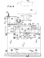
- severing station 300 for severing an article component from the article, more particularly filter rod portion 450 of the article includes a cutting element 310, aperture 330, air cylinder 340, and ball slide unit 370.
- Cutting element 310 is used to pass through to sever one smoking article 20 after it is positioned at a selected location in aperture 330 by members 510 and 520 of robot 503.
- Cutting element 310 is mounted on carriage 360 of ball slide unit 370 between opposing carriage bracket 361 and clamp plate 362.
- Carriage 360 is mounted on two slide bars 368 and 369, which are mounted in two end blocks 371 and 372 that are respectively supported by spanner bars 373 and 374.
- Ball slide unit 370 provides a straight, one-dimensional cutting path along which element 310 will travel and may be, for example, model no. DS3-2-C, manufactured by Stelron.
- the stroke length of air cylinder 340 thus defines the maximum stroke length for element 310, for example, 2.54 cm.
- Movement of element 310 is controlled by air cylinder 340 which actuates piston rod 350 to move carriage 360 and carriage bracket 361 in a lateral direction along slide bars 368 and 369.
- Piston rod 350 is attached to carriage bracket 361 by cylinder block 379.
- Piston rod 350 is connected to air cylinder 340 and is moved back and forth by air cylinder 340.
- Air cylinder 340 is preferably a single action device in that a force is applied to extend piston 350 and a spring (not shown) returns piston 350 to its rest position following a lowering of the force.
- Air cylinder 340 is preferably part no. FOS-04-1.000-3 (Flat 1 air cylinder-single acting-spring return-19mm (3/4 inch) bore-25mm (1 inch stroke)) manufactured and available from Bimba.
- Air inlet 381 of the cylinder is preferably model no. 11752-1 (hose fitting-#10-32 to 3.2 mm (1/8 inch) I.D. hose) manufactured by Clippard.
- Air cylinder 340 is supported by end plate 383 which is also used to separate front side plate 364 from rear side plate 375 and to give overall stability to the cutting unit. Further stability to the cutting unit is provided by support angles 377 and 378 attached to front side plate 364 and rear side plate 375 and table 12.
- a solenoid (not shown in the Figures) is used to control delivery of compressed air to inlet 381 to initiate the cutting process.
- the solenoid is preferably actuated by microprocessor 1000 in response to article 20 being placed in the selected second location.
- the solenoid also can be controlled manually by a switch mounted in the vicinity of the cutting apparatus.
- Alternate devices for moving cutting element 310 in response to article 20 being placed in the second position include stepper motors, linear actuators, rack and pinion mechanisms and similar devices.
- Cutting element 310 is preferably a sharp blade, more preferably a conventional single-edged razor blade having a blade length of 3.88 cm.
- Blade 310 is mounted to carriage 360 between opposing carriage bracket 361 and clamp plate 362.
- the razor-blade side of clamp plate 362 includes recess 363 which is configured to hold razor blade 310 in the recess at a fixed angle relative to the piston direction. The angle must be sufficient so that the blade severs the smoking article (as contrasted to crushing the article) and passes completely through the cross section of article 20, e.g., 25 to 35 degrees used, more preferably 30 degrees.
- roll pin 366 maybe used to keep razor blade 310 in place during the cutting motion.
- article 20 prior to the severing operation, is preferably placed in orientation station 900 by robot 503.
- This permits robot 503 to grip article 20 at the mouth end of filter portion 450 between opposing members 510 and 520 and maneuver article 20 axially into aperture 330 extending through front side plate 364 and blade guard 365 to a selected distance or depth.
- the diameter of aperture 330 is preferably larger than the circumference of the article to be cut to provide tolerance for inserting and extracting articles 20 having a range of circumferences.
- the diameter of aperture 330 is 8. 33 mm (0.328 inches), or cigarettes having a circumference in the range of 22-25 mm.
- Aperture 330 can be modified to accommodate smoking articles of other diameters or cross-sectional shapes by replacing front side plate 364 and blade guard 365 with a front side plate and blade guard having an aperture of appropriate dimensions.
- aperture 330 also includes countersink 367 in blade guard 365 to assist in the initial guiding of article 330 into the cutting position.
- robot 503 holds article 20 by its filter end portion 450 with the portion of the article to be severed in the cutting path of blade 310.
- air cylinder 340 is actuated to move razor blade 310 to sever article 20 at the designated portion.
- Microprocessor 1000 positions robot 503 in response to the previously identified length of the article segment to be severed, e.g., filter portion 450 of a cigarette.
- robot 503 is programmed to move members 510 and 520 to grip article 320 at, for example, at the mouth end or at midpoint of the filter segment 450, and to insert article 320 to a depth so that razor blade 310 will sever article 320 at a location that is a selected distance from the end of the filter segment to be severed.
- the selected distance is preferably 2 mm.
- the robot may be programmed to cut the smoking article at a distance of 29 mm from the mouth end of the filter.
- the razor blade will cut through the tobacco and not the filter material.
- severing station 300 provides for severing a filter rod portion from a smoking article so that the automatic test station can perform characterization tests both on the complete article and its filter (or other) component.
- the precision and accuracy of the cutting operation is determined by the precision and accuracy of the mechanical parts of the computer controlled apparatus as contrasted to an operator's manual ability.
- the quality of the cut also has been made more reproducible, thereby enhancing statistical analysis and accuracy of tests performed on a plurality of like components severed from a plurality of like smoking articles.
- deshredding station 400 for removing tobacco shreds from the severed component includes housing 400, deshredder motor 410, deshredder tool 420, vacuum port 430, and air stream conduit440.
- Housing 400 has a motor end 402 and an aperture end 404.
- Deshredder motor410 which is mounted in end 402 of housing 400, is used to rotate deshredder tool 420 at a selected speed in the range of 3000 to 4000 rpm, preferably 3600 rpm.
- Robot 503 inserts filter portion 450 (shown in cross section) in end 404 of housing 400 in axial alignment with motor 410 and tool 420.
- End 404 has an aperture for receiving filter portion 450.
- the aperture dimension is preferably selected to receive smoking article filter portions having a circumference in a range of circumferences, e.g., 22-25 mm, and to permit annular air flow into housing 400 when filter portion 450 is inserted.
- Preferred aperture dimensions are 9 to 10 mm in diameter.
- Presenting end 452 of portion 450 is preferably brought within a preselected distance, e.g., 2 mm, of the tip of deshredder tool 420.
- a stream of high pressure air from source 442 is blown onto presenting end 452 of filter 450 through conduit 440.
- Rotating deshredder tool 420 may contact the tobacco shreds attached to filter 450 that are not loosened by the stream of air, to loosen those shreds not removed by the air stream.
- vacuum port 430 also is provided to exhaust out through a flow path to vacuum 433 any loosened tobacco shreds that have become detached from the end of the filter by the air stream, deshredder tool 420 or both.
- Deshredder motor 410 is held in housing 400 by way of screws 412. Attached to the end of the deshredder motor shaft 414 is deshredder tool 420, which is held in place by way of set screw 413. Deshredder tool 420 can be made of a hard material, but most preferably it is made out of a hard steel or aluminum alloy, for example, having a black oxide finish.
- tool 120 preferably has two prongs 422 and 423 extending from tip 421 such that tip 421 has a rectangular cross section of width w and length d.
- Length d corresponds to the diameter in which tip 421 rotates (which is less than the corresponding diameter of the filter portion), for example, in the range of 5 to 5.9mm (0.2 to 0.23 inches), preferably 5mm (0.2 inches).
- Each prong 424 and 423 preferably is a four sided structure of first dimension w, preferably about 1.1mm (0.045 inches), and second dimension t, preferably about 1.3mm (0.053 inches), such that each prong projects a distance h, preferably about 3.8mm (0.15 inches), from the unmilled rectangular body of tip 421 of tool 420.
- Prongs 422 and 423 are preferably located at the periphery of distance d, separated by space s of about 2.4mm (0.095 inches).
- deshredder tool 420 may have an alternate motion, for example, a circular back-and-forth motion where the tool rotates half of a revolution before it reverses direction.
- Tool 420 also may have an alternate tip configuration, for example, more than two prongs, prongs at angles relative to one another, a hook, a scythe, a flat loop, or a spiral or helical section.
- Conduit 440 which is preferably simply formed of standard 3.2mm (1/8 inch) outer diameter copper tubing having an inner diameter of 2mm (0.07 inch) terminates adjacent deshredder tool 420. Such tubing is malleable and conduit 440 can be bent, as necessary, to place tip 444 in close proximity to the selected location and deshredder tool 420, directed at presenting end 452 of filler 450. Tip 444 is preferably formed by cutting tube 440 transversely, but may also be provided with a configured shape to provide a nozzle.
- Source 442 is connected to conduit 440 and provides an air stream, preferably a high pressure air stream in the range of 70 to 300 kPa (10 to 40 psi), more preferably 150 kPa (20 psi).
- Source 442 preferably has an on condition and an off condition for regulating air flow depending upon whether or not a filter portion is in position or being brought into position to be deshredded.
- inert high-pressure gas for example, nitrogen, and other types of gas jet delivery systems could be used.
- Vacuum source 433 is attached to vacuum port 430 of housing 400 by conduit 432.
- Vacuum source 433 is preferably a 13mm (1/2 inch) diameter house vacuum and has a suction in the range of 380 to 640mm (15 to 25 in.)-Hg, sufficient to exhaust all of the gas provided through conduit 400 and maintain a nominal or slight negative pressure inside housing 400.
- Vacuum source 433 serves to entrain and to exhaust tobacco shreds which become detached from filter 150 and has an on condition and an off condition depending upon whether or not a filter portion is in position or being brought into position to be deshredded.
- severed filter portion 450 is gripped between opposing members 510 and 520 of robot 503 at a first location, preferably the same position used for the severing operation, and is maneuvered axially into end 404 of housing 400.
- Robot 503 is provided with information specifying the length of the filter and positions filter 450 to a predetermined selected location corresponding to placing presenting tobacco end 452 of the filter 450 into the deshredding area.
- microprocessor 1000 issues an instruction to activate each of deshredder motor 410 to cause tool 420 to rotate, air source 442 to commence air flow through conduit 440, and vacuum source 443 to commence exhausting air through port 430 during or prior to insertion.
- Robot 503 then holds filter 450 in the selected position for a period of 1 to 4 seconds, more preferably 2 seconds. At the end of this period, microprocessor 1000 issues instructions to deactivate deshredder motor 410, air source 442, and vacuum 433, and to remove the deshredded filter 450 from the deshredder housing 400.
- tool 420, source 442 and vacuum 433 may be continuously operating.
- tool 420 may be initially immersed in a relatively thick plug of tobacco shreds thereby to loosen the shreds, or may not be in contact with any shreds.
- the distance between the tip of tool 420 and the end of filter 450 is selected so that if the tool does not contact any shreds in area 452, the air flow has either removed them or is sufficient to remove them during the time period the filter is maintained at the selected location, and there is an insufficient force to retain the shreds on the filter end to withstand both the air flow and tool 420.
- deshredding tool 420 may provide a turbulent air stream that facilitates loosening the shreds.
- a plurality of measuring instruments are provided as stations to perform characterization tests on one or more groups of like articles 20 or components, specifically filter portions 450, of articles 20.
- Circumference station 600 measures the circumference of one article 20 at a time.
- Station 600 is mounted at a fixed position on table 12 within the reach of robot 503.
- Station 600 is preferably a commercial device, model Filtrona Lasermike FLM 200, available from Fidus Insert ent Corporation, Richmond Virginia.
- the commercial device was modified for use with the present invention by enlarging the sample holder portion to facilitate insertion and extraction of article 20 by robot 503.
- robot 503 grips article 20 and maneuvers to insert article 20 axially into the sample holder to a selected depth based on the previously encoded nominal length of article 20 (not shown), whereupon microprocessor 1000 sends a command to device 600 instructing device 600 to read the circumference.
- Article 20 is then rotated through one revolution as conventional laser measuring techniques are used to take 200 measurements of the diameter of article 20.
- Device 600 then calculates the circumference of article 20 from the average of the diameter measurements. This data is communicated to microprocessor 1000 and stored, optionally in host computer 1200, for subsequent tabulation and analysis.
- robot 503 extracts article 20 from the sample holder and advances it to the next station, in accordance with the program for processing that particular article 20.
- PDI station 700 measures the pressure drop and filter ventilation of one article 20 at a time.
- Station 700 is secured at a fixed location on table 12 within the reach of robot 503.
- Station 700 is preferably a commercial device, model PDI/ODI available from Fidus Corporation, Richmond Virginia.
- the commercial device is normally manually operated.
- the device was modified to install conventionally a suitable number of solenoids and relays so that microprocessor 1000 could control the "manual" operation of the instrument.
- microprocessor 1000 issues appropriate instructions first to robot 503 to manipulate one article 20 and to insert or release article 20 into the commercial receiving portion of the instrument, and, second, to actuate the relays to drive the solenoids thereby to conduct normally the pressure drop and ventilation measurement procedures.
- microprocessor 1000 is connected to the data port of the instrument so that the measurements obtained are communicated to microprocessor 1000 for recordation and tabulation. Following the measurement procedures, microprocessor 1000 controls the instrument to eject the article 20 to the receiving portion, whereupon robot 503 is instructed to grip again article 20 and maneuver it to the next station, in accordance with the program for processing that particular article 20.
- PDI station 800 measures the filter pressure drop of one filter rod portion 450 at a time.
- Station 800 is secured at a fixed location on table 12 within the reach of robot 503.
- Station 800 is preferably a commercial device, model PDI available from Fidus Corporation, Richmond Virginia.
- the commercial device is normally manually operated.
- the device was modified to install a suitable number of solenoids and relays in a conventional manner so that microprocessor 1000 could control the "manual" operation of the instrument.
- microprocessor 1000 issues appropriate instructions first to robot 503 to manipulate filter rod portion 450 and to release or insert filter 450 into the commercial receiving portion of the instrument, and, second, to actuate the relays to drive the solenoids thereby to conduct normally the filter pressure drop measurement.
- microprocessor 1000 is connected to the data port of the instrument so that the measurement obtained is communicated to microprocessor 1000 for recordation and tabulation. Following the measurement procedure, microprocessor 1000 controls the insert ent to eject the filter portion 450 to a trash receptacle.
- Station 850 measures the filter length of a filter rod portion 450 one at a time.
- Station 850 is secured at a fixed location on table 12 within the reach of robot 503.
- Station 850 is preferably a commercial device, model EG-250 available from Ono Sokki Co., Ltd., Tokyo Japan.
- the commercial device is a digital linear gauge for measuring thicknesses between a movable tip and a fixed base (not shown) having a data communications port for providing measured data and is normally manually operated.
- the device was modified to install an air cylinder and a solenoid in a conventional manner so that microprocessor 1000 could control the "manual" operation of the instrument, specifically the movement of the tip relative to the base.
- microprocessor 1000 issues appropriate instructions to robot 503 to manipulate filter rod portion 450 in axial alignment between the tip and the base of the commercial receiving portion of the instrument, and to the solenoid and air cylinder to move the tip to engage the aligned filter portion to conduct the filter length measurement and then to release the filter.
- microprocessor 1000 is connected to the data port of the instrument so that the measurement obtained is communicated to microprocessor 1000 for recordation and tabulation.
- microprocessor 1000 instructs robot 503 to grip filter 450, then controls the solenoid and air cylinder and the tip is retracted from the base so that filter portion 450 is removed by robot 503 and maneuvered to the next station, in accordance with the program for processing that particular filter portion 450.
- microprocessor 1000 The data collected by microprocessor 1000 are typically transferred to a controller or host computer 1200 for processing.
- Computer 1200 includes a PC/286 microprocessor device, a model SUN SPARCstation available from Sun Microsystems, Inc. and a conventional database computer.
- An Ethernet network (not shown) links microprocessor 1000, computer 1200 and the various test instruments for communications therebetween.
- barcode reader 1300 is connected to computer 1200 for entering sample identification codes for each sample set of a plurality of like articles 20 and creating a database file of the pertinent data regarding the nominal dimensions and characteristics of the articles in that sample.
- the sample set is inserted into a designated hopper 110 of hopper feeder 100 which is correlated to the bar code given.
- Database files are shared by computer 1200 and microprocessor 1000 and stored on a software disk that is accessible over the Ethernet network.
- Test station 10 in accordance with the present embodiment can test filtered or non-filtered cigarettes and other types of smoking articles having circumferences in the range of 22 to 25 mm and nominal lengths of 80 to 120 mm.
- Use of the hopper feeder device 100 provides a plurality of hoppers 110, e.g., eighteen, to be filled, each hopper 110 holding up to 30 cigarettes in a given sample set.
- test station 10 can be programmed to measure any of article pressure drop, filter ventilation, filter pressure drop, circumference, cigarette length, and filter length on any number of plurality of articles in each sample set in any sequence, provided that tests on a complete article are completed before tests are conducted on a component severed from that article.
- test station 10 begins when the operator loads a sample set into hopper feeder 100, provides the sample set with an identifying bar code, and creates a test sequence database file for that set in one of host computer 1200 or microprocessor 1000.
- the database file typically includes the number of articles 20 in the sample set, the nominal length of the articles and their filter portions and other pertinent dimensions of the articles or their components and the test protocol for that sample set, i.e., which tests are to be performed on how many of the articles in that sample set
- This information is then logged in microprocessor 1000 or computer 1200 by the operator at operator workstation 1100 as each sample set is deposited into a designated hopper 110.
- the operator can continue loading the system with up to eighteen samples, each sample having a bar code and an associated database. For example, a typical sample set will have twenty-five articles. The operator may instruct that each article will be measured for article length, circumference, and pressure drop, and for filter ventilation, pressure drop, and length. Alternately, the operator may instruct that only ten of the twenty-five articles will be measured for article length and circumference and filter length, and all twenty-five of the articles will be measured for article pressure drop, filter ventilation, and filter pressure drop. In this regard, robot 503 will not maneuver the other fifteen articles to those stations not selected.
- the operator program station 10 with a particular order for testing the articles in each sample set, such thatthe selected ten tests for article length will be taken off the first five articles and the last five articles, whereas the ten tests for filter length will be taken off alternating filter rod portions. Other combinations thus could be created as desired.
- computer 1200 is used to write the selected barcodes into a "worklist" file that will be used by microprocessor 1000.
- the operator moves to microprocessor 1000 and answers software generated questions which define the station's operating mode.
- Microprocessor 1000 initializes robot 503 and verifies that the communications network is operational. It then waits for the operator to enter the command at operator workstation 1100 to actually start sample testing. After entering this start command, the operator is then free to perform other tasks.
- Microprocessor 1000 transfers the barcode worklist and database specification files from computer 1200 data disk, reads the first barcode from the worklist, extracts the selected test requirements from the corresponding specification file and displays this information on a monitor (e.g., at operator workstation 1100) for operator observation.
- a monitor e.g., at operator workstation 1100
- a sample of cigarettes from hopper 110 is fed into feeding device 140.
- the first cigarette is fed from device 140 onto and down chute 220 so that it comes to rest against stop 222 with filter end 450 down, where its length is measured by camera 230.
- Robot 503 picks up the cigarette by the tobacco end at a distance of about 65 mm from the filter end, rotates it to a filter end up position and sequences it through, for example, station 700 which obtains the article pressure drop and ventilation measurement and station 600 which obtains the article circumference measurement as called for in the specification file.
- Microprocessor 1000 operates each instrument, reads and records the data, and displays the test values on the system monitor. If no further tests are to be conducted, robot 503 may move article 20 to a waste receptacle.
- robot 503 For conducting subsequent tests on filter portion 450, robot 503 retrieves article 20 from the last smoking article test station and places and releases article 20 in reorientation fixture 900. Robot 503 then moves hand 500 to rotate and grip article 20 by the filter end. The cigarette is placed in the severing station 300 and filter 450 is cut approximately two mm longer than the nominal length obtained from the specification file. The sheared tobacco rod drops through a chute and into a trash receptacle (not shown). Robot 503 then takes filter 450 to deshredding station 400, where any remaining tobacco is dislodged and vacuumed into a holding tank.
- Robot 503 then sequences the filter 450 through stations 850 and 800 for measuring the filter length and filter pressure drop (or vice versa) as indicated in the specification file.
- the filter pressure drop test is preferably conducted last. Accordingly, following the measurement, a blast of air blows filter 450 out of the instrument, into a chute which leads to a trash receptacle (not shown).
- Test station microprocessor 1000 operates each instrument, collects and records the data and displays the data obtained from these instruments on the system monitor.
- test data file After all cigarettes in the sample set have been tested, the accumulated data are transmitted in a test data file to host computer 1200. It has been found that it requires approximately thirty minutes to run a sample of 25 cigarettes through the full compliment of tests.
- microprocessor 1000 searches host computer 1200 for another worklist. Additional sample sets can be loaded into hopper feeder 110 and a second worklist containing barcodes having corresponding databases can be created in host computer 1200. If such a second worklist is found, it is transferred to microprocessor 1000 and the testing continues; otherwise, robot 503 is moved to its rest position.
- test station of the present invention has a flexible design for optimal use. If host computer 1200 fails, the necessary coding and parameter entry can be entered directly into microprocessor 1000. The data are stored in microprocessor 1000 and sent to the host computer 1200 when communications have been restored. If hopper feeder 100 is not functional, sample sets can be loaded by hand into feeder mechanism 140.
- the operator also can bypass a faulty instrument by not requesting a specific test in the test specification file of the database.
- the operator also may use the test instruments manually, for example, if the robot is not operational or only a select few tests are required. This may be accomplished by inserting a cigarette into an instrument, manually activating the insert ent to conduct the test, and instructing microprocessor 1000 when to read the data obtained by the instrument. The data are typically saved in microprocessor 1000 and sent to host computer 1200 when the testing is completed.
- Test station 10 also looks for operational problems while it is running, such as a cigarette not feeding from the hopper, an insert ent blocked by a previously tested cigarette/filter, or a cigarette not being properly placed into an insert ent. When one of these situations is detected, test station 10 tries to correct the problem. The station operating mode specified by the operator determines how test station 10 reacts if it is unable to correct the problem.
- microprocessor 1000 When microprocessor 1000 is operating in a mode having an operator in the area and it is unable to correct automatically a problem, it signals the operator that a problem has occured, stops robot 503 and requests the operator to correct the problem and restart the operation. When restarted, operation resumes where the problem was detected.
- microprocessor 1000 When operating in an unattended mode and microprocessor 1000 is unable to correct the problem, it bypasses the problem instrument and goes to the next instrument in the test sequence. Microprocessor 1000 also loads an appropriate failure message into a log file which is transmitted to host computer 1200 along with the test data. This file may be used later to determine what caused the problem.
- test station in accordance with the preferred embodiment described above was constructed using the instruments described above. Its operation was compared to a manually operated test station using the same type of instruments.
- the robotic test station requires about twice the time to process samples as the manually operated station, it facilitates continuous and consistent handling of cigarettes and filters and is capable of running a full compliment of tests on 36 sample sets of 25 articles per day. It also provides for assured testing of smoking articles and filters from these article, an improved characterization of the samples, and can operate unattended. Improvements in speed could be obtained by selection of a different robot device and spacing of the various test stations.
Landscapes
- Manufacturing Of Cigar And Cigarette Tobacco (AREA)
Applications Claiming Priority (2)
| Application Number | Priority Date | Filing Date | Title |
|---|---|---|---|
| US657677 | 1984-10-04 | ||
| US07/657,677 US5214969A (en) | 1991-02-19 | 1991-02-19 | Automatic testing of a plurality of smoking articles |
Publications (2)
| Publication Number | Publication Date |
|---|---|
| EP0500302A2 true EP0500302A2 (de) | 1992-08-26 |
| EP0500302A3 EP0500302A3 (en) | 1993-10-27 |
Family
ID=24638199
Family Applications (1)
| Application Number | Title | Priority Date | Filing Date |
|---|---|---|---|
| EP19920301289 Withdrawn EP0500302A3 (en) | 1991-02-19 | 1992-02-18 | Automatic testing of a plurality of smoking articles |
Country Status (3)
| Country | Link |
|---|---|
| US (1) | US5214969A (de) |
| EP (1) | EP0500302A3 (de) |
| JP (1) | JPH0595777A (de) |
Cited By (4)
| Publication number | Priority date | Publication date | Assignee | Title |
|---|---|---|---|---|
| WO2005046365A1 (en) * | 2003-11-17 | 2005-05-26 | G.D S.P.A. | A system for monitoring and controlling machines used in the manufacture of tobacco products |
| EP2082652A1 (de) * | 2008-01-24 | 2009-07-29 | Hauni Maschinbau AG | Entnahme von einzelnen stabförmigen Artikeln der Tabak verarbeitenden Industrie aus einem Massenstrom |
| CN109549252A (zh) * | 2018-12-20 | 2019-04-02 | 颐中(青岛)实业有限公司 | 智能烟灰桶 |
| US20220358682A1 (en) * | 2020-09-16 | 2022-11-10 | China Tobacco Yunnan Industrial Co., Ltd | Device and method for detecting cigarette fly ash by gray-scale difference based on machine vision (mv) |
Families Citing this family (27)
| Publication number | Priority date | Publication date | Assignee | Title |
|---|---|---|---|---|
| DE4107077A1 (de) * | 1991-01-22 | 1992-08-13 | Stell Karl Wilhelm Dipl Ing Dr | Verfahren zum messen von werkstuecken |
| US5363885A (en) * | 1993-06-02 | 1994-11-15 | R. J. Reynolds Tobacco Company | Robotic sample preparation system and method |
| US6075882A (en) * | 1997-06-18 | 2000-06-13 | Philip Morris Incorporated | System and method for optically inspecting cigarettes by detecting the lengths of cigarette sections |
| DE69917740T2 (de) * | 1998-07-22 | 2005-06-16 | Japan Tobacco Inc. | Vorrichtung zur prüfung einer stabförmigen probe |
| CN1099259C (zh) * | 1999-11-09 | 2003-01-22 | 钱强 | 卷烟和嘴棒圆周在生产中的测量和控制法 |
| US20030145868A1 (en) * | 2002-02-01 | 2003-08-07 | Halder Robert S. | Linear puffer |
| US20040065142A1 (en) * | 2002-06-21 | 2004-04-08 | Automated Control Systems, Inc. | Flow testing system and method |
| US7435940B2 (en) | 2003-03-12 | 2008-10-14 | Flatfrog Laboratories Ab | System and a method of determining the position of a radiation emitting element |
| US20050022831A1 (en) * | 2003-07-30 | 2005-02-03 | Hirsch David W. | Method for automatically controlling the quality of cigarettes produced in a manufacturing process |
| WO2005026938A2 (en) | 2003-09-12 | 2005-03-24 | O-Pen Aps | A system and method of determining a position of a radiation scattering/reflecting element |
| US7442914B2 (en) | 2003-09-12 | 2008-10-28 | Flatfrog Laboratories Ab | System and method of determining a position of a radiation emitting element |
| DE202007001196U1 (de) * | 2006-08-30 | 2007-05-31 | Tews Elektronik Dipl.-Ing. Manfred Tews | Filterstabmeßstation zur Messung der Masse eines Weichmachers, der Feuchtigkeit und/oder des trockenen Filtermaterials in einem Filterstab |
| EP2740434A4 (de) | 2011-08-04 | 2015-03-18 | Olympus Corp | Medizinischer manipulator und steuerungsverfahren dafür |
| JP6009840B2 (ja) | 2011-08-04 | 2016-10-19 | オリンパス株式会社 | 医療機器 |
| JP6000641B2 (ja) | 2011-08-04 | 2016-10-05 | オリンパス株式会社 | マニピュレータシステム |
| JP5931497B2 (ja) | 2011-08-04 | 2016-06-08 | オリンパス株式会社 | 手術支援装置およびその組立方法 |
| JP6021484B2 (ja) | 2011-08-04 | 2016-11-09 | オリンパス株式会社 | 医療用マニピュレータ |
| JP6021353B2 (ja) | 2011-08-04 | 2016-11-09 | オリンパス株式会社 | 手術支援装置 |
| CN103732173B (zh) | 2011-08-04 | 2016-03-09 | 奥林巴斯株式会社 | 手术器具和医疗用机械手 |
| JP5841451B2 (ja) | 2011-08-04 | 2016-01-13 | オリンパス株式会社 | 手術器具およびその制御方法 |
| JP5936914B2 (ja) | 2011-08-04 | 2016-06-22 | オリンパス株式会社 | 操作入力装置およびこれを備えるマニピュレータシステム |
| JP6081061B2 (ja) * | 2011-08-04 | 2017-02-15 | オリンパス株式会社 | 手術支援装置 |
| JP6005950B2 (ja) | 2011-08-04 | 2016-10-12 | オリンパス株式会社 | 手術支援装置及びその制御方法 |
| CN103648425B (zh) | 2011-08-04 | 2016-10-19 | 奥林巴斯株式会社 | 医疗用机械手和手术支援装置 |
| JP5953058B2 (ja) | 2011-08-04 | 2016-07-13 | オリンパス株式会社 | 手術支援装置およびその着脱方法 |
| KR101800189B1 (ko) * | 2012-04-30 | 2017-11-23 | 삼성전자주식회사 | 수술 로봇의 힘 제어 장치 및 방법 |
| US10869496B2 (en) | 2018-08-28 | 2020-12-22 | R.J. Reynolds Tobacco Company | Systems and methods for testing heat-not-burn tobacco products |
Family Cites Families (33)
| Publication number | Priority date | Publication date | Assignee | Title |
|---|---|---|---|---|
| US2016156A (en) * | 1934-09-29 | 1935-10-01 | Int Cigar Mach Co | Duplex cigar transfer |
| NL248221A (de) * | 1959-02-10 | |||
| US3048281A (en) * | 1959-06-25 | 1962-08-07 | Int Cigar Mach Co | Transfer for cigar machines |
| US3150390A (en) * | 1959-08-11 | 1964-09-29 | Veeder Root Inc | Apparatus for trimming sequentially the opposite ends of an elongated workpiece |
| US3404688A (en) * | 1965-06-04 | 1968-10-08 | Reynolds Tobacco Co R | Apparatus for disassembling filter and cigarette assemblies |
| SE323021B (de) * | 1967-04-20 | 1970-04-20 | Seragnoli Gd Sas | |
| GB1251051A (de) * | 1967-10-09 | 1971-10-27 | ||
| US3732874A (en) * | 1972-02-25 | 1973-05-15 | Loew Theatres Inc | Smoking machine |
| US3985252A (en) * | 1973-04-17 | 1976-10-12 | Molins Limited | Feeding rod-like articles |
| US3850029A (en) * | 1973-07-16 | 1974-11-26 | Measurex Corp | Apparatus for measuring the compressibility of cigarettes and the like |
| US4177670A (en) * | 1976-11-26 | 1979-12-11 | Hauni-Werke Korber & Co. Kg. | Method and apparatus for multiple testing of wrappers of cigarettes for porosity |
| JPS6049867B2 (ja) * | 1977-09-20 | 1985-11-05 | ダイセル化学工業株式会社 | たばこ用フイルタの性状測定方法および装置 |
| JPS5548598A (en) * | 1978-09-29 | 1980-04-07 | Fujitsu Fanuc Ltd | Load reducing device of industrial robot |
| CH638614A5 (en) * | 1979-03-26 | 1983-09-30 | Burrus & Cie | Method of determining the degree of ventilation by means of at least one part of the outer surface of a rod-like element and apparatus for carrying out the method |
| GB2061527B (en) * | 1979-10-19 | 1983-10-05 | Imp Group Ltd | Testing air-permeable rod-like articles |
| US4355535A (en) * | 1979-10-19 | 1982-10-26 | Imperial Group Limited | Apparatus for automatically measuring the properties of air-permeable rod-like articles |
| CH634205A5 (fr) * | 1980-01-24 | 1983-01-31 | Baumgartner Papiers Sa | Dispositif de prelevement automatique d'un echantillon de filtre ou de cigarette. |
| GB2073003B (en) * | 1980-02-26 | 1984-05-02 | Molins Ltd | Filter cigarette making machine |
| IT1195041B (it) * | 1980-07-11 | 1988-09-28 | Hauni Werke Koerber & Co Kg | Procedimento e dispositivo per il controllo del funzionamento di dispositivi di controllo di una macchina per fabbricare articoli da fumo a forma di bastoncini |
| DE3111318C2 (de) * | 1981-03-23 | 1983-03-17 | B.A.T. Cigaretten-Fabriken Gmbh, 2000 Hamburg | Verfahren zur Bestimmung des Zugwiderstandes und/oder der Gasdurchlässigkeit eines Prüflings sowie Einrichtung zur Durchführung eines solchen Verfahrens |
| DE3111319C2 (de) * | 1981-03-23 | 1985-07-25 | B.A.T. Cigaretten-Fabriken Gmbh, 2000 Hamburg | Einrichtung zur Bestimmung der Kompressibilität von Tabakmaterialien |
| US4484591A (en) * | 1981-04-14 | 1984-11-27 | Hauni-Werke Korber & Co. Kg. | Method of testing and classifying cigarettes or the like |
| FR2545410B3 (fr) * | 1983-05-03 | 1986-02-21 | Gillet Ets E | Procede et dispositif de positionnement et griffage de grumes pour alimentation automatique de scies a grumes |
| IT1174127B (it) * | 1983-06-14 | 1987-07-01 | Hauni Werke Koerber & Co Kg | Dispositivo di controllo ottico per sigarette |
| US4708574A (en) * | 1985-07-05 | 1987-11-24 | D. W. Zimmerman Mfg., Inc. | Apparatus for handling objects |
| SU1316788A1 (ru) * | 1985-08-13 | 1987-06-15 | Специальное Конструкторское Бюро Алмазно-Расточных И Радиально-Сверлильных Станков | Разгрузочно-загрузочное устройство |
| US4637564A (en) * | 1985-11-04 | 1987-01-20 | Fts Equipment Manufacturing Co. | Dual reel continuous wire winding machine with robotic reel loading mechanism |
| US4911374A (en) * | 1986-01-21 | 1990-03-27 | Philip Morris Incorporated | System and method for use in delaminating bobbins of paper material |
| US4821972A (en) * | 1986-01-21 | 1989-04-18 | Philip Morris Incorporated | System and method for use in handling and delaminating bobbins of paper material |
| IT1207663B (it) * | 1987-04-15 | 1989-05-25 | Gd Spa | Untia' di prelievo di sigarette campione da una massa di sigarette |
| IT1225028B (it) * | 1988-07-28 | 1990-10-31 | Gd Spa | Apparecchiatura per effettuare operazioni di controllo su sigarette |
| US4911028A (en) * | 1989-02-09 | 1990-03-27 | Philip Morris Incorporated | Apparatus and method for carrying out measurements on a bobbin of sheet material |
| GB8916589D0 (en) * | 1989-07-20 | 1989-09-06 | Tabac Fab Reunies Sa | Control process and apparatus for the production of cigarette filters |
-
1991
- 1991-02-19 US US07/657,677 patent/US5214969A/en not_active Expired - Fee Related
-
1992
- 1992-02-18 EP EP19920301289 patent/EP0500302A3/en not_active Withdrawn
- 1992-02-19 JP JP4070415A patent/JPH0595777A/ja active Pending
Cited By (8)
| Publication number | Priority date | Publication date | Assignee | Title |
|---|---|---|---|---|
| WO2005046365A1 (en) * | 2003-11-17 | 2005-05-26 | G.D S.P.A. | A system for monitoring and controlling machines used in the manufacture of tobacco products |
| US8770204B2 (en) | 2003-11-17 | 2014-07-08 | G.D S.P.A. | System for monitoring and controlling machines used in the manufacture of tobacco products |
| EP2082652A1 (de) * | 2008-01-24 | 2009-07-29 | Hauni Maschinbau AG | Entnahme von einzelnen stabförmigen Artikeln der Tabak verarbeitenden Industrie aus einem Massenstrom |
| DE102008005964A1 (de) * | 2008-01-24 | 2009-07-30 | Hauni Maschinenbau Ag | Entnahme von einzelnen stabförmigen Artikeln der Tabak verarbeitenden Industrie aus einem Massenstrom |
| US8156828B2 (en) | 2008-01-24 | 2012-04-17 | Hauni Maschinenbau Ag | Sampling of individual rod-like articles of the tobacco-processing industry from a massflow |
| CN109549252A (zh) * | 2018-12-20 | 2019-04-02 | 颐中(青岛)实业有限公司 | 智能烟灰桶 |
| US20220358682A1 (en) * | 2020-09-16 | 2022-11-10 | China Tobacco Yunnan Industrial Co., Ltd | Device and method for detecting cigarette fly ash by gray-scale difference based on machine vision (mv) |
| US11670007B2 (en) * | 2020-09-16 | 2023-06-06 | China Tobacco Yunnan Industrial Co., Ltd | Device and method for detecting cigarette fly ash by gray-scale difference based on machine vision (MV) |
Also Published As
| Publication number | Publication date |
|---|---|
| JPH0595777A (ja) | 1993-04-20 |
| EP0500302A3 (en) | 1993-10-27 |
| US5214969A (en) | 1993-06-01 |
Similar Documents
| Publication | Publication Date | Title |
|---|---|---|
| US5214969A (en) | Automatic testing of a plurality of smoking articles | |
| EP1405690B1 (de) | Robotergerät und Verfahren zur Montierung von Ventilschaften auf Radfelgen | |
| US5800777A (en) | Method and apparatus for automatic sample preparation and handling | |
| EP0361891B1 (de) | Apparat zum Montieren und Schweissen von Endstopfen an Kernbrennstoffhüllrohren und zum Überprüfen von Endstopfenschweissungen auf automatischer Basis | |
| CN109443116A (zh) | 电子雷管生产线 | |
| US5058260A (en) | Wire processing apparatus | |
| EP0667121A2 (de) | Einrichtung zur Einfädelung und Zusammensetzung mit einem Quetschwerkzeug einer chirurgischen Nadel mit Faden | |
| WO2018014586A1 (zh) | 采样切割装置及种子自动切片采样设备 | |
| CN112564435B (zh) | 电机转子滚花轴与转子铁芯的自动装配方法 | |
| CN110293074B (zh) | 刀具自动分拣设备 | |
| US20230083943A1 (en) | Medical swab storage method and medical swab storage device | |
| CN210449930U (zh) | 刀具分拣设备 | |
| EP1849417A3 (de) | Eigenständiges Senkverfahren und entsprechende Vorrichtung | |
| EP2753905A2 (de) | Verfahren zur feststellung des vorliegens von vorgegebenen eigenschaften eines behältererzeugnisses und vorrichtung zur durchführung des verfahrens | |
| US6926651B2 (en) | Method of and apparatus for replacing cutting implements in severing machines | |
| EP4348217B1 (de) | Automatisierte arbeitsstation und verfahren zur handhabung histologischer proben in dem einbettschritt | |
| CN109263059A (zh) | 智能植板机 | |
| US5419441A (en) | Needle blank sorting apparatus | |
| CN211904205U (zh) | 滤棒横截面检测装置 | |
| US5150719A (en) | Apparatus and method for removing tobacco shreds from a cigarette filter | |
| EP0500298A2 (de) | Apparat und Verfahren zum Greifen einer Zigarette | |
| EP0500300A2 (de) | Apparat und Verfahren zum Zerschneiden einer Zigarette | |
| CN113125231A (zh) | 自动抽梗分梗装置及方法 | |
| US6516970B2 (en) | Feeder device for orienting elongated mechanical components therein | |
| JP7352043B1 (ja) | 有価金属を含むスパークプラグの先端を機械的に抽出する自動システム |
Legal Events
| Date | Code | Title | Description |
|---|---|---|---|
| PUAI | Public reference made under article 153(3) epc to a published international application that has entered the european phase |
Free format text: ORIGINAL CODE: 0009012 |
|
| AK | Designated contracting states |
Kind code of ref document: A2 Designated state(s): AT BE CH DE DK ES FR GB GR IT LI LU MC NL PT SE |
|
| PUAL | Search report despatched |
Free format text: ORIGINAL CODE: 0009013 |
|
| AK | Designated contracting states |
Kind code of ref document: A3 Designated state(s): AT BE CH DE DK ES FR GB GR IT LI LU MC NL PT SE |
|
| 18D | Application deemed to be withdrawn |
Effective date: 19940329 |