EP0500467A1 - Verfahren zur kontinuierlichen Kontrolle einer endlosen Bahn, sowie Vorrichtung zur Durchführung dieses Verfahrens - Google Patents
Verfahren zur kontinuierlichen Kontrolle einer endlosen Bahn, sowie Vorrichtung zur Durchführung dieses Verfahrens Download PDFInfo
- Publication number
- EP0500467A1 EP0500467A1 EP92400451A EP92400451A EP0500467A1 EP 0500467 A1 EP0500467 A1 EP 0500467A1 EP 92400451 A EP92400451 A EP 92400451A EP 92400451 A EP92400451 A EP 92400451A EP 0500467 A1 EP0500467 A1 EP 0500467A1
- Authority
- EP
- European Patent Office
- Prior art keywords
- strip
- injection system
- drops
- machine
- dye
- Prior art date
- Legal status (The legal status is an assumption and is not a legal conclusion. Google has not performed a legal analysis and makes no representation as to the accuracy of the status listed.)
- Granted
Links
Images


Classifications
-
- B—PERFORMING OPERATIONS; TRANSPORTING
- B65—CONVEYING; PACKING; STORING; HANDLING THIN OR FILAMENTARY MATERIAL
- B65H—HANDLING THIN OR FILAMENTARY MATERIAL, e.g. SHEETS, WEBS, CABLES
- B65H26/00—Warning or safety devices, e.g. automatic fault detectors, stop-motions, for web-advancing mechanisms
- B65H26/02—Warning or safety devices, e.g. automatic fault detectors, stop-motions, for web-advancing mechanisms responsive to presence of irregularities in running webs
-
- B—PERFORMING OPERATIONS; TRANSPORTING
- B41—PRINTING; LINING MACHINES; TYPEWRITERS; STAMPS
- B41F—PRINTING MACHINES OR PRESSES
- B41F15/00—Screen printers
- B41F15/14—Details
- B41F15/16—Printing tables
- B41F15/18—Supports for workpieces
- B41F15/24—Supports for workpieces for webs
-
- B—PERFORMING OPERATIONS; TRANSPORTING
- B41—PRINTING; LINING MACHINES; TYPEWRITERS; STAMPS
- B41F—PRINTING MACHINES OR PRESSES
- B41F17/00—Printing apparatus or machines of special types or for particular purposes, not otherwise provided for
- B41F17/003—Special types of machines for printing textiles
- B41F17/005—Supports for workpieces; Devices for securing the workpieces to the supports
Definitions
- the present invention essentially relates to a process for the continuous control of an endless strip, in particular a strip intended to entrain a fabric which must receive successive impressions, the offset of which must be zero or reduced to the minimum in order to thus preserve the aesthetics of the printed fabric.
- This invention also relates to a machine for continuously monitoring an endless belt for the implementation of this method.
- textile printing machines generally comprise an endless sheet or band surrounding two cylinders, one of which is rotated and above which cylinders or flat frames are arranged. successive printing capable of printing patterns of different colors on a strip of fabric entrained by the strip and sandwiched between this strip and the printing cylinders.
- the sheet or the endless strip generally has a sandwich structure of several more or less thick layers of elastomeric material, of fabric, etc., capable of allowing the printing of the fabric resting on the strip by compression of the cylinders or flat frames. printing on the fabric.
- the endless belt is obviously driven at constant speed, but the speed of movement of the band remains irregular despite everything due to local-possible defects or variations in the internal structure of this band, these defects or variations in structure giving the band somewhat variable elasticity.
- Such cropping can reach a few tenths of a millimeter, which is detrimental to the appearance of the fabric. Indeed, one cannot tolerate a cropping which is higher than approximately one tenth of a millimeter.
- the present invention achieves this goal.
- the subject of the invention is a process for the continuous control of an endless belt, for example intended to drive a fabric which must receive successive impressions, the cropping of which must be zero or reduced to a minimum, characterized in that '' it consists of periodically depositing drops of dye, such as ink, on a stretched strip of tape driven at a constant speed, continuously measuring the differences between two drops and comparing these differences with a reference value to thus control the regularity of the current local speed of travel of the strip and therefore its structural homogeneity.
- '' it consists of periodically depositing drops of dye, such as ink, on a stretched strip of tape driven at a constant speed, continuously measuring the differences between two drops and comparing these differences with a reference value to thus control the regularity of the current local speed of travel of the strip and therefore its structural homogeneity.
- each measured difference value between the two aforementioned adjacent drops is memorized, the average of the different measured differences is then calculated and the difference between the difference currently measured and said average is made.
- a drop of dye from a single injection system is periodically deposited on the stretched strand of the strip so as to obtain on the stretched strand of the strip a succession of drops. , and the differences between the successive drops are measured continuously and downstream of the injection system to determine the average value of the position of the neutral fiber in the strip.
- the position of the neutral fiber in the strip is substantially constant, it will therefore be certain that the running speed of said strip will also be substantially constant and that consequently this strip will be suitable for printing a fabric without defects in framing. It should also be added that precise knowledge of the position of the neutral fiber will allow the operator of the textile printing machine to preset the said machine so as to obtain the required printing precision.
- the invention also relates to a machine for implementing the method meeting one or the other of the above characteristics, this machine being of the type comprising a frame supporting two cylinders capable of causing an endless belt to rotate. to be checked, and being characterized in that said frame carries above the strip, at least a dye injection system and at least one camera connected to a computer, while an encoder is mechanically connected to the output shaft of a rotary drive motor of one of the two cylinders and is electrically connected to said injection system and to said camera.
- a first gantry situated on the side of the cylinder driven by the engine and supporting a first dye injection system as well as two cameras, and a second gantry located on the side of the other cylinder and supporting a second dye injection system.
- the other aforementioned cylinder is removably mounted on a rolling carriage or also meshing on the frame and capable of passing under the two aforementioned gantries.
- the cylinder driven by the motor is removably mounted on a support fixed to the frame and carrying the aforementioned motor and encoder.
- the machine according to this invention is further characterized in that it is functionally associated with a fabric printing machine or the like to regulate the speed thereof.
- the printing machine itself can include all the means according to this invention for carrying out continuous control of the current speed of travel of the endless strip which drives the fabric to print it.
- Band B if its control proves satisfactory, may be transferred to a printing machine (not shown), or else, without departing from the scope of the invention, the printing machine may be integrated into the printing machine. control visible in Figure 1.
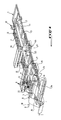
- This control machine comprises a frame 1 supporting two cylinders or rollers allowing the belt B to be driven in rotation along arrow F, and namely a motorized or front cylinder 2 and a rear or traction cylinder 3.
- the rear cylinder 3 is removably mounted on a self-propelled carriage 4 meshing with a rack 5 secured to the frame 1.
- the front cylinder 2 is removably mounted on a support 6 fixed, by any suitable means, to the frame 1 of the machine. On this fixed support is mounted a motor 7 for driving the cylinder 2 in rotation, and an encoder 8 is mechanically connected to the motor shaft 7.
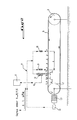
- the encoder 8 is electrically connected by a file 9 to two injection systems 10, 11 of dye, such as for example ink, and to two video cameras 12, 13, as can be seen in the figures 1, 2 and 3.
- a first gantry located on the side of the front or motorized cylinder 2 has been shown at 14 in FIG. 1, this gantry supporting, by any suitable means, the two cameras 12, 13 and one of the two dye injection systems .
- the other dye injection system 10 is integral with a second gantry 15 which, like the gantry 14 is provided with an access 16 and a control console 17.
- the gantries 14 and 15 are mounted rolling or sliding on the frame 1 of the machine and the injection systems 10 and 11, as well as the cameras 12 and 13 are carried by these gantries above and below the belt endless B, it being understood that the self-propelled carriage 4 can pass under said gantries 14,15, as will be described later.
- a computer 0 shown diagrammatically in FIGS. 2 and 3 and connected to the video cameras 12 and 13 allows the calculation of the cropping and the position of the neutral fiber of band B, as will be described in detail below.
- the two gantries 14 and 15 are moved back on the frame 1 towards the right end of this figure, and the self-propelled carriage 4 supporting the rear cylinder 3 is advanced on the frame 1, passing under the gantries 14 and 15, towards and relatively near the support 6 carrying the motorized cylinder 2.
- This motorized cylinder 2 is detached, by one of its ends from the support 6, and the endless band B to be checked is threaded (shown in dotted lines on the left part of FIG. 1) on the cylinder 2 which is then put back on its support 6.
- an overhead crane, hoist or the like shown diagrammatically at 18, is used to reassemble the rear cylinder 3 (or 3a) threaded in the band B, on the self-propelled carriage 4 located very close to the support 6 carrying the front cylinder 2.
- the strip B is thus in place, that is to say surrounding the cylinders 2 and 3, the two gantries 14 and 15 are brought to the left in FIG. 1, in the position visible in this figure by passing over the strip B.
- the carriage 4 is brought to the right of FIG. 1 to take the position visible in this figure, it being understood that the strip B will, thanks to the carriage 4, be tensioned.
- the tension of the strip will be adjusted by means of jacks (not shown) by an operator who will control the prescribed value of tension on indicators identified at 19 in FIG. 1.
- a strip of adhesive film 20 which is clearly visible in FIG. 1 is glued to the endless strip B in order to serve as a printing medium for the drops of ink leaving the injection systems 10 and 11.
- the system is originally designed to give 900,000 points from the encoder 8 per revolution of the drive cylinder 2.
- the encoder 8 gives the order to the injection systems 10 and 11 for each movement p of the strip B, to simultaneously print a drop a, b on the sheet, after which the cropping caused by the irregularities of the strip will be checked by the camera 12, downstream of the injection system 11.
- the differences X i between two drops ab are measured by the camera 12 connected to the computer 0 in which each difference value between two drops is stored.
- the computer calculates the average of the different deviations X i measured by the camera 12, that is to say:
- the computer 0 will make the difference between the difference X i currently measured by the camera 12 and the aforementioned average of the differences X, to give the value d i of the cropping, that is:
- the screen of the computer 0 will indicate in the form of a graph the different values of d i according to the position of the strip B.
- a single ink injection system is used, namely the system 11, and the two identical and simultaneous reading video cameras 12 and 13 which are mounted on the gantry 14 above the sheet B and spaced apart.
- a distance D 1000 mm.
- the cameras 12 and 13 can accurately measure the value p, which is the distance between two successive drops deposited by the ink injection system 11.
- the objective is to determine the position or the average value of the neutral fiber f, which constitutes a particularly useful parameter for operators using fabric printing machines with an endless belt of the type of those currently considered. .
- the system according to the invention will give the current or individual values f i of the neutral fiber as a function of the position on the sheet B, and the computer 0 will calculate and give the average value of the neutral fiber, ie:
- a method and a machine for continuous control of an endless belt for a fabric printing machine have therefore been produced according to the invention, this method and this machine making it possible to measure the cropping and the average position with great precision. of the neutral fiber of the strip.
- the equipment of the machine according to the invention will in particular include ink injection systems, video cameras and an encoder having high precision and resolution so as to obtain the precision required in the results of measurement, and thus to guarantee the users of fabric printing machines against any web defect which would be detrimental to the printing of fabrics.
- machine according to the invention could be incorporated or combined with a fabric printing machine in any suitable manner whatsoever.
Landscapes
- Engineering & Computer Science (AREA)
- Textile Engineering (AREA)
- Mechanical Engineering (AREA)
- Treatment Of Fiber Materials (AREA)
- Screen Printers (AREA)
- Supplying Of Containers To The Packaging Station (AREA)
- Control And Other Processes For Unpacking Of Materials (AREA)
- Photographic Processing Devices Using Wet Methods (AREA)
- Sewing Machines And Sewing (AREA)
- Paper (AREA)
- Extrusion Moulding Of Plastics Or The Like (AREA)
- Controlling Rewinding, Feeding, Winding, Or Abnormalities Of Webs (AREA)
- Tyre Moulding (AREA)
Applications Claiming Priority (2)
| Application Number | Priority Date | Filing Date | Title |
|---|---|---|---|
| FR9102041A FR2672879B1 (fr) | 1991-02-20 | 1991-02-20 | Procede de controle en continu d'une bande sans fin et machine pour la mise en óoeuvre de ce procede. |
| FR9102041 | 1991-02-20 |
Publications (2)
| Publication Number | Publication Date |
|---|---|
| EP0500467A1 true EP0500467A1 (de) | 1992-08-26 |
| EP0500467B1 EP0500467B1 (de) | 1996-06-19 |
Family
ID=9409935
Family Applications (1)
| Application Number | Title | Priority Date | Filing Date |
|---|---|---|---|
| EP92400451A Expired - Lifetime EP0500467B1 (de) | 1991-02-20 | 1992-02-20 | Verfahren zur kontinuierlichen Kontrolle einer endlosen Bahn, sowie Vorrichtung zur Durchführung dieses Verfahrens |
Country Status (8)
| Country | Link |
|---|---|
| US (1) | US5295571A (de) |
| EP (1) | EP0500467B1 (de) |
| AT (1) | ATE139511T1 (de) |
| CA (1) | CA2061533A1 (de) |
| DE (1) | DE69211576T2 (de) |
| FR (1) | FR2672879B1 (de) |
| MY (1) | MY108642A (de) |
| ZA (1) | ZA92770B (de) |
Cited By (3)
| Publication number | Priority date | Publication date | Assignee | Title |
|---|---|---|---|---|
| EP0649068A3 (de) * | 1993-08-02 | 1995-10-11 | Xerox Corp | Verfahren und Vorrichtung zur Ausrichtung mehrerer Bilder in einem xerographischen System. |
| US6273313B1 (en) * | 1999-06-02 | 2001-08-14 | The Proctor & Gamble Company | Process and apparatus for controlling the registration of converting operations with prints on a web |
| WO2007073784A1 (de) * | 2005-12-27 | 2007-07-05 | Lurgi Zimmer Gmbh | Verfahren und vorrichtung zur produktionsüberwachung von endlosformkörpern wie filamenten und filamentbündeln |
Families Citing this family (15)
| Publication number | Priority date | Publication date | Assignee | Title |
|---|---|---|---|---|
| US5774153A (en) * | 1991-11-15 | 1998-06-30 | Heidelberger Druckmaschinen Aktiengesellschaft | Digital precision positioning system |
| CN1071264C (zh) * | 1994-02-14 | 2001-09-19 | 曼弗雷德·R·屈恩勒 | 有静电保持基层的精确定位对准的印刷设备等的输送系统 |
| JP3779364B2 (ja) * | 1996-01-26 | 2006-05-24 | 株式会社湯山製作所 | 薬剤収納取出装置 |
| NL1007246C2 (nl) * | 1997-08-26 | 1999-03-01 | Stork Brabant Bv | Drukinrichting met kleefstofrakel. |
| SE512662C2 (sv) * | 1998-03-12 | 2000-04-17 | Sunds Defibrator Ind Ab | Transportör samt anläggning för balning av pappersmassa |
| DE10035402A1 (de) * | 2000-07-19 | 2002-01-31 | Phoenix Ag | Einrichtung zur Überwachung einer Förderanlage |
| US6585108B2 (en) * | 2001-09-17 | 2003-07-01 | Tonny A. Travis | Method and apparatus for monitoring and controlling conveyor position |
| US7047852B2 (en) * | 2001-10-24 | 2006-05-23 | Kimberly-Clark Worldwide, Inc. | Feedforward control system for an elastic material |
| US7012210B2 (en) * | 2002-08-09 | 2006-03-14 | Lockheed Martin Corporation | Singulation detection system for objects used in conjunction with a conveyor system |
| US6758327B1 (en) | 2003-01-07 | 2004-07-06 | Rexnord Industries, Inc. | Conveyor drive assembly and method of operation |
| US7210361B2 (en) * | 2005-09-26 | 2007-05-01 | Hsin Fa Kang | Device for measuring the tightness of a transmission belt |
| US20080236108A1 (en) * | 2007-03-29 | 2008-10-02 | Parmley Steven M | Package Wrapping Machine with Detection of Lip Features of Trayed Products to be Wrapped |
| WO2012079174A1 (en) * | 2010-12-15 | 2012-06-21 | Anubis Manufacturing Consultants Corp. | System for and method of measuring flow of a powder |
| US9228909B1 (en) * | 2014-05-13 | 2016-01-05 | Google Inc. | Methods and systems for sensing tension in a timing belt |
| CN112892985B (zh) * | 2021-01-15 | 2022-06-14 | 东营红星劳保用品有限责任公司 | 一种纺织布料用阻燃材料定量涂抹装置 |
Citations (3)
| Publication number | Priority date | Publication date | Assignee | Title |
|---|---|---|---|---|
| US3559568A (en) * | 1969-01-14 | 1971-02-02 | Armstrong Cork Co | Method of controlling pattern repeat length |
| FR2453096A1 (fr) * | 1979-04-06 | 1980-10-31 | Toshin Kogyo Co | Procede et machine de serigraphie automatique |
| US4690051A (en) * | 1986-02-12 | 1987-09-01 | Miyakoshi Printing Machinery Co., Ltd. | Method of image registration in a web fed, multiple printing rotary press |
Family Cites Families (5)
| Publication number | Priority date | Publication date | Assignee | Title |
|---|---|---|---|---|
| DE257417C (de) * | ||||
| HU180827B (en) * | 1979-08-10 | 1983-04-29 | Koezponti Banyaszati Fejleszte | Method for measuring the resistance to wear of endless driving devices during operation |
| FR2487795B1 (fr) * | 1980-07-30 | 1986-01-31 | Oritel Sa | Installation pour la surveillance d'un convoyeur a tapis sans fin |
| SU1114598A1 (ru) * | 1983-03-15 | 1984-09-23 | Днепропетровский завод шахтной автоматики | Устройство контрол проскальзывани ленты конвейера |
| DE3933196C2 (de) * | 1989-10-05 | 1994-05-26 | Schenck Ag Carl | Verfahren und Vorrichtung zur Überwachung des Bandlaufs eines Förderbandes oder einer Bandwaage |
-
1991
- 1991-02-20 FR FR9102041A patent/FR2672879B1/fr not_active Expired - Lifetime
-
1992
- 1992-01-09 US US07/820,456 patent/US5295571A/en not_active Expired - Lifetime
- 1992-02-03 ZA ZA92770A patent/ZA92770B/xx unknown
- 1992-02-18 MY MYPI92000258A patent/MY108642A/en unknown
- 1992-02-19 CA CA002061533A patent/CA2061533A1/en not_active Abandoned
- 1992-02-20 EP EP92400451A patent/EP0500467B1/de not_active Expired - Lifetime
- 1992-02-20 DE DE69211576T patent/DE69211576T2/de not_active Expired - Fee Related
- 1992-02-20 AT AT92400451T patent/ATE139511T1/de not_active IP Right Cessation
Patent Citations (3)
| Publication number | Priority date | Publication date | Assignee | Title |
|---|---|---|---|---|
| US3559568A (en) * | 1969-01-14 | 1971-02-02 | Armstrong Cork Co | Method of controlling pattern repeat length |
| FR2453096A1 (fr) * | 1979-04-06 | 1980-10-31 | Toshin Kogyo Co | Procede et machine de serigraphie automatique |
| US4690051A (en) * | 1986-02-12 | 1987-09-01 | Miyakoshi Printing Machinery Co., Ltd. | Method of image registration in a web fed, multiple printing rotary press |
Cited By (3)
| Publication number | Priority date | Publication date | Assignee | Title |
|---|---|---|---|---|
| EP0649068A3 (de) * | 1993-08-02 | 1995-10-11 | Xerox Corp | Verfahren und Vorrichtung zur Ausrichtung mehrerer Bilder in einem xerographischen System. |
| US6273313B1 (en) * | 1999-06-02 | 2001-08-14 | The Proctor & Gamble Company | Process and apparatus for controlling the registration of converting operations with prints on a web |
| WO2007073784A1 (de) * | 2005-12-27 | 2007-07-05 | Lurgi Zimmer Gmbh | Verfahren und vorrichtung zur produktionsüberwachung von endlosformkörpern wie filamenten und filamentbündeln |
Also Published As
| Publication number | Publication date |
|---|---|
| EP0500467B1 (de) | 1996-06-19 |
| ATE139511T1 (de) | 1996-07-15 |
| MY108642A (en) | 1996-10-31 |
| DE69211576T2 (de) | 1997-02-06 |
| CA2061533A1 (en) | 1992-08-21 |
| US5295571A (en) | 1994-03-22 |
| FR2672879A1 (fr) | 1992-08-21 |
| ZA92770B (en) | 1992-11-25 |
| FR2672879B1 (fr) | 1994-12-09 |
| DE69211576D1 (de) | 1996-07-25 |
Similar Documents
| Publication | Publication Date | Title |
|---|---|---|
| EP0500467B1 (de) | Verfahren zur kontinuierlichen Kontrolle einer endlosen Bahn, sowie Vorrichtung zur Durchführung dieses Verfahrens | |
| EP0214214B1 (de) | Vorrichtung und verfahren zum positionieren von gegenständen, insbesondere von farbdruckzylindern, in rotations-offset-pressen | |
| EP1132203B1 (de) | Verfahren und Vorrichtung zum automatischen Voreinstellen des Registers von Rotationsdruckmaschinen | |
| EP2834594B1 (de) | Methode und vorrichtung zum messen der planheit eines metallprodukts | |
| FR2760686A1 (fr) | Appareil et procede de travail sur une longueur de matiere en bande | |
| EP1918100B1 (de) | Druckmaschine und Druckverfahren | |
| FR2531941A1 (fr) | Machine pour la decoupe de pieces dans une matiere en bande | |
| CH662308A5 (fr) | Appareil a imprimer sur une bande en mouvement. | |
| EP0967469B1 (de) | Messung interner Spannungen in einem transparenten Material, wie Fensterscheiben | |
| FR2597793A1 (fr) | Procede et dispositifs pour regler l'instant de declenchement du broyage lateral de l'encre pour des machines d'impression | |
| FR2689059A1 (fr) | Machine à imprimer à tête d'impression interchangeable. | |
| EP0732198B1 (de) | Verfahren und Vorrichtung zum Regeln der Feuchtigkeit einer Materialbahn in einer Druckmaschine | |
| FR2513608A1 (fr) | Appareil de manutention de feuilles minces de materiau | |
| FR2670927A1 (fr) | Machine graphique et procede de controle de materiau d'impression utilisant un tel rouleau de materiau d'impression en feuille bobine sur une ame, et rouleau utilisable pour une telle machine et un tel procede. | |
| FR2550995A1 (fr) | Procede et dispositif de reglage assurant l'adaptation aux reperes et la conformite aux longueurs d'impression dans les imprimeuses flexographiques | |
| FR2508259A1 (fr) | Appareil d'impression thermique, avec deplacement en deux temps du film-couleur | |
| FR2969530A1 (fr) | Dispositif de rainurage d'une feuille mince | |
| FR2687605A1 (fr) | Procede et dispositif de detection, dans une machine, de la position de venue en contact de deux pieces dont l'une au moins est mobile. | |
| FR2966381A1 (fr) | Dispositif d'impression | |
| FR2695590A1 (fr) | Procédé et dispositif pour orienter des feuilles. | |
| BE1006806A6 (fr) | Systeme et machine d'impression multiple en continu. | |
| FR2895310A1 (fr) | Dispositif d'encrage et procede d'ajustement correspondant | |
| FR2597390A1 (fr) | Machine pour decouper des feuilles de longueurs variables dans une bande de materiau de support d'impression ou analogue. | |
| EP4107505B1 (de) | Vorrichtung zum sammeln von in der umgebung enthaltenen partikeln auf einem transparenten klebeband durch impaktion und zugehöriges verfahren | |
| FR2566705A1 (fr) | Dispositif d'impression a enclume cylindrique, notamment pour titres de transport |
Legal Events
| Date | Code | Title | Description |
|---|---|---|---|
| PUAI | Public reference made under article 153(3) epc to a published international application that has entered the european phase |
Free format text: ORIGINAL CODE: 0009012 |
|
| AK | Designated contracting states |
Kind code of ref document: A1 Designated state(s): AT BE CH DE DK ES FR GB GR IT LI LU NL PT SE |
|
| 17P | Request for examination filed |
Effective date: 19930222 |
|
| 17Q | First examination report despatched |
Effective date: 19940708 |
|
| 111Z | Information provided on other rights and legal means of execution |
Free format text: AT BE CH DE DK ES FR GB GR IT LI LU NL PT SE |
|
| GRAA | (expected) grant |
Free format text: ORIGINAL CODE: 0009210 |
|
| REG | Reference to a national code |
Ref country code: CH Ref legal event code: PVP |
|
| AK | Designated contracting states |
Kind code of ref document: B1 Designated state(s): AT BE CH DE DK ES FR GB GR IT LI LU NL PT SE |
|
| PG25 | Lapsed in a contracting state [announced via postgrant information from national office to epo] |
Ref country code: GR Free format text: LAPSE BECAUSE OF FAILURE TO SUBMIT A TRANSLATION OF THE DESCRIPTION OR TO PAY THE FEE WITHIN THE PRESCRIBED TIME-LIMIT Effective date: 19960619 Ref country code: GB Effective date: 19960619 Ref country code: DK Effective date: 19960619 |
|
| REF | Corresponds to: |
Ref document number: 139511 Country of ref document: AT Date of ref document: 19960715 Kind code of ref document: T |
|
| REF | Corresponds to: |
Ref document number: 69211576 Country of ref document: DE Date of ref document: 19960725 |
|
| REG | Reference to a national code |
Ref country code: CH Ref legal event code: NV Representative=s name: TROESCH SCHEIDEGGER WERNER AG |
|
| ITF | It: translation for a ep patent filed | ||
| PG25 | Lapsed in a contracting state [announced via postgrant information from national office to epo] |
Ref country code: SE Effective date: 19960919 Ref country code: PT Effective date: 19960919 |
|
| PG25 | Lapsed in a contracting state [announced via postgrant information from national office to epo] |
Ref country code: ES Free format text: LAPSE BECAUSE OF FAILURE TO SUBMIT A TRANSLATION OF THE DESCRIPTION OR TO PAY THE FEE WITHIN THE PRESCRIBED TIME-LIMIT Effective date: 19960930 |
|
| GBV | Gb: ep patent (uk) treated as always having been void in accordance with gb section 77(7)/1977 [no translation filed] |
Effective date: 19960619 |
|
| PG25 | Lapsed in a contracting state [announced via postgrant information from national office to epo] |
Ref country code: LU Free format text: LAPSE BECAUSE OF NON-PAYMENT OF DUE FEES Effective date: 19970228 Ref country code: BE Effective date: 19970228 |
|
| PGFP | Annual fee paid to national office [announced via postgrant information from national office to epo] |
Ref country code: ES Payment date: 19970228 Year of fee payment: 6 |
|
| PLBE | No opposition filed within time limit |
Free format text: ORIGINAL CODE: 0009261 |
|
| STAA | Information on the status of an ep patent application or granted ep patent |
Free format text: STATUS: NO OPPOSITION FILED WITHIN TIME LIMIT |
|
| 26N | No opposition filed | ||
| BERE | Be: lapsed |
Owner name: S.A. ROLLIN Effective date: 19970228 |
|
| PGFP | Annual fee paid to national office [announced via postgrant information from national office to epo] |
Ref country code: FR Payment date: 19990209 Year of fee payment: 8 |
|
| PGFP | Annual fee paid to national office [announced via postgrant information from national office to epo] |
Ref country code: AT Payment date: 19990211 Year of fee payment: 8 |
|
| PGFP | Annual fee paid to national office [announced via postgrant information from national office to epo] |
Ref country code: NL Payment date: 19990224 Year of fee payment: 8 |
|
| PGFP | Annual fee paid to national office [announced via postgrant information from national office to epo] |
Ref country code: DE Payment date: 19990301 Year of fee payment: 8 |
|
| PGFP | Annual fee paid to national office [announced via postgrant information from national office to epo] |
Ref country code: CH Payment date: 19990310 Year of fee payment: 8 |
|
| PG25 | Lapsed in a contracting state [announced via postgrant information from national office to epo] |
Ref country code: AT Free format text: LAPSE BECAUSE OF NON-PAYMENT OF DUE FEES Effective date: 20000220 |
|
| PG25 | Lapsed in a contracting state [announced via postgrant information from national office to epo] |
Ref country code: LI Free format text: LAPSE BECAUSE OF NON-PAYMENT OF DUE FEES Effective date: 20000229 Ref country code: CH Free format text: LAPSE BECAUSE OF NON-PAYMENT OF DUE FEES Effective date: 20000229 |
|
| PG25 | Lapsed in a contracting state [announced via postgrant information from national office to epo] |
Ref country code: NL Free format text: LAPSE BECAUSE OF NON-PAYMENT OF DUE FEES Effective date: 20000901 |
|
| REG | Reference to a national code |
Ref country code: CH Ref legal event code: PL |
|
| PG25 | Lapsed in a contracting state [announced via postgrant information from national office to epo] |
Ref country code: FR Free format text: LAPSE BECAUSE OF NON-PAYMENT OF DUE FEES Effective date: 20001031 |
|
| NLV4 | Nl: lapsed or anulled due to non-payment of the annual fee |
Effective date: 20000901 |
|
| PG25 | Lapsed in a contracting state [announced via postgrant information from national office to epo] |
Ref country code: DE Free format text: LAPSE BECAUSE OF NON-PAYMENT OF DUE FEES Effective date: 20001201 |
|
| REG | Reference to a national code |
Ref country code: FR Ref legal event code: ST |
|
| PG25 | Lapsed in a contracting state [announced via postgrant information from national office to epo] |
Ref country code: IT Free format text: LAPSE BECAUSE OF NON-PAYMENT OF DUE FEES;WARNING: LAPSES OF ITALIAN PATENTS WITH EFFECTIVE DATE BEFORE 2007 MAY HAVE OCCURRED AT ANY TIME BEFORE 2007. THE CORRECT EFFECTIVE DATE MAY BE DIFFERENT FROM THE ONE RECORDED. Effective date: 20050220 |