EP0500486B1 - Joint brosse segmenté et méthode de fabrication - Google Patents
Joint brosse segmenté et méthode de fabrication Download PDFInfo
- Publication number
- EP0500486B1 EP0500486B1 EP92630008A EP92630008A EP0500486B1 EP 0500486 B1 EP0500486 B1 EP 0500486B1 EP 92630008 A EP92630008 A EP 92630008A EP 92630008 A EP92630008 A EP 92630008A EP 0500486 B1 EP0500486 B1 EP 0500486B1
- Authority
- EP
- European Patent Office
- Prior art keywords
- seal
- backing plate
- side plate
- tabs
- bristles
- Prior art date
- Legal status (The legal status is an assumption and is not a legal conclusion. Google has not performed a legal analysis and makes no representation as to the accuracy of the status listed.)
- Expired - Lifetime
Links
Images

Classifications
-
- F—MECHANICAL ENGINEERING; LIGHTING; HEATING; WEAPONS; BLASTING
- F16—ENGINEERING ELEMENTS AND UNITS; GENERAL MEASURES FOR PRODUCING AND MAINTAINING EFFECTIVE FUNCTIONING OF MACHINES OR INSTALLATIONS; THERMAL INSULATION IN GENERAL
- F16J—PISTONS; CYLINDERS; SEALINGS
- F16J15/00—Sealings
- F16J15/16—Sealings between relatively-moving surfaces
- F16J15/32—Sealings between relatively-moving surfaces with elastic sealings, e.g. O-rings
- F16J15/3284—Sealings between relatively-moving surfaces with elastic sealings, e.g. O-rings characterised by their structure; Selection of materials
- F16J15/3288—Filamentary structures, e.g. brush seals
-
- Y—GENERAL TAGGING OF NEW TECHNOLOGICAL DEVELOPMENTS; GENERAL TAGGING OF CROSS-SECTIONAL TECHNOLOGIES SPANNING OVER SEVERAL SECTIONS OF THE IPC; TECHNICAL SUBJECTS COVERED BY FORMER USPC CROSS-REFERENCE ART COLLECTIONS [XRACs] AND DIGESTS
- Y10—TECHNICAL SUBJECTS COVERED BY FORMER USPC
- Y10T—TECHNICAL SUBJECTS COVERED BY FORMER US CLASSIFICATION
- Y10T29/00—Metal working
- Y10T29/49—Method of mechanical manufacture
- Y10T29/49229—Prime mover or fluid pump making
- Y10T29/49297—Seal or packing making
-
- Y—GENERAL TAGGING OF NEW TECHNOLOGICAL DEVELOPMENTS; GENERAL TAGGING OF CROSS-SECTIONAL TECHNOLOGIES SPANNING OVER SEVERAL SECTIONS OF THE IPC; TECHNICAL SUBJECTS COVERED BY FORMER USPC CROSS-REFERENCE ART COLLECTIONS [XRACs] AND DIGESTS
- Y10—TECHNICAL SUBJECTS COVERED BY FORMER USPC
- Y10T—TECHNICAL SUBJECTS COVERED BY FORMER US CLASSIFICATION
- Y10T29/00—Metal working
- Y10T29/49—Method of mechanical manufacture
- Y10T29/49789—Obtaining plural product pieces from unitary workpiece
- Y10T29/49792—Dividing through modified portion
-
- Y—GENERAL TAGGING OF NEW TECHNOLOGICAL DEVELOPMENTS; GENERAL TAGGING OF CROSS-SECTIONAL TECHNOLOGIES SPANNING OVER SEVERAL SECTIONS OF THE IPC; TECHNICAL SUBJECTS COVERED BY FORMER USPC CROSS-REFERENCE ART COLLECTIONS [XRACs] AND DIGESTS
- Y10—TECHNICAL SUBJECTS COVERED BY FORMER USPC
- Y10T—TECHNICAL SUBJECTS COVERED BY FORMER US CLASSIFICATION
- Y10T29/00—Metal working
- Y10T29/49—Method of mechanical manufacture
- Y10T29/49789—Obtaining plural product pieces from unitary workpiece
- Y10T29/49794—Dividing on common outline
Definitions
- This invention relates to the field of brush seals, and more particularly to the application of brush seals to turbomachines, according to the preambles of claims 1, 4 and 7.
- Brush seals are generally useful for axially segregating a plurality of adjacent annular fluid volumes in axial flow machines.
- an axial flow gas turbine engine typically has a plurality of such adjacent volumes wherein it is desirable to maintain predetermined fluid volumes and/or pressures during machine operation.
- a brush seal provides this segregating effect by employing a flexible partition which is circumferentially disposed about and bears against the surface of a rotatable shaft, the partition bridging the gap between the shaft and its corresponding opposing surface. Effective partitioning by a brush seal occurs over a broad operating range by accommodating thermal and centrifugal growth, thereby maintaining desired fluid volume and pressure by limiting or preventing fluid inflow or outflow across the plane of the partition.
- Brush seals of the prior art have a closed annular configuration comprising a pair of annularly shaped plates which capture a plurality of tightly packed bristles therebetween.
- the bristels are circumferentially arrayed about the annulus such that they project radially inwardly toward the rotational axis of the seal and shaft.
- the outwardly-facing bristles of an outwardly facing brush seal bear against the inner surface of a structure disposed radially outward of the seal.
- the brush seal is installed about a rotatable shaft by axially sliding the seal along the shaft to its designated axial location and then affixing it at that location to a static structure using an appropriate attachment and retention method.
- This method of installation necessitates the time-consuming removal of those shaft-disposed machine elements with their associated hardware which are located in intermediate positions between the accessible shaft end and the designated brush seal.
- a segmented brush seal comprising an annular backing plate having inner and outer diameters and an axial centerline therethrough, an annular side plate having an inner diameter larger than the inner diameter of the backing plate, an outer diameter and an axial centerline therethrough coaxial to the axial centerline of the annular backing plate, the coaxial plates sandwiching a plurality of circumferentially arrayed bristles extending radially inwardly at a constant circumferential skew angle with respect to the side plate, the backing plate and the side plate each comprising a plurality of contiguous annular segments, characterized in that a plurality of tabs extend radially inwardly from the side plate inner diameter, that each of the contiguous annular segments is delimited by two circumferentially disposed welded zones, each welded zone fusing a cross-section of the plates, the sandwiched bristles, and one of said radially inwardly extending tabs, and each welded zone extending radially from a
- a method of manufacturing a segmented brush seal having an annular backing plate with inner and outer diameters and an axial centerline therethrough, an annular side plate having an inner diameter greater than the inner diameter of the backing plate, an outer diameter and an axial centerline therethrough coaxial to the axial centerline of the backing plate, the coaxial plates sandwiching a plurality of circumferentially arrayed bristles extending radially inwardly at a constant circumferential skew angle with respect to the side plate, characterized by comprising the steps of: (a) providing said side plate with a plurality of radially inwardly extending tabs, (b) welding together the plates, the sandwiched bristles, and tabs at circumferentially spaced locations of the seal to form welded zones extending radially from the radially inner ends of the tabs to an outermost diameter of the seal, each of the welded zones being substantially parallel to the lcoal bristle skew angle, and (c)
- a method of manufacturing a segmented brush seal having an annular backing plate having inner and outer diameters and an axial centerline therethrough, an annular side plate having an outer diameter smaller than the outer diameter of the backing plate, an inner diameter and an axial centerline therethrough coaxial to the axial centerline of the backing plate, the coaxial plates sandwiching a plurality of circumferentially arrayed bristles extending radially outwardly at a constant circumferential skew angle with respect to the side plate, characterized by comprising the steps of: (a) providing said side plate with a plurality of radially outwardly extending tabs, (b) welding together the plates, the sandwiched bristles, and tabs at circumferentially spaced locations of the seal to form welded zones extending radially from the radially outer end of the tabs to an innermost diameter of the seal, the welded zones being substantially parallel to the local bristle skew angle, and (c) radially severing
- a welded zone is formed which is wide enough to permit bifurcation of the seal through the welded area, and in another embodiment two parallel welds are formed and the seal is bifurcated between the parallel welds.
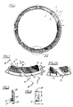
- Fig. 1 is a planar view of a brush seal of the present invention.
- Fig. 2 is an enlarged view of a portion of the seal shown in Fig. 1.
- Fig. 3 is a cross-section of the seal taken through a section of Fig. 2.
- Fig. 4 is a cross-section of the seal also taken through a section of Fig. 2.
- Fig. 5 shows an alternate embodiment of Fig. 2.
- Fig. 6 is a planar view of an alternate embodiment of the present invention.
- the brush seal 10 for partitioning axially adjacent annular volumes according to the present invention is shown.
- the brush seal 10 comprises an annular backing plate 20 axially spaced apart from an annular side plate 25, and further has a plurality of tightly packed bristles 30 sandwiched therebetween.
- the bristles 30 extend radially inwardly at a constant circumferential skew angle with respect to the side plate 25, and with respect to the coaxial centerlines of the backing plate and side plates 20, 25.
- the side plate 25 of one configuration has an inner diameter 27 larger than the inner diameter 22 of the backing plate 20.
- the outer diameters 24, 29 of the backing plate 20, and side plate 25, respectively, are dimensioned to accommodate circumferential welding of the paired outer diameters 24, 29 of the annular plates 20, 25.
- a cross-section of this assembly depicted in Fig. 3, shows the side plate 25 and backing plate 20 which sandwich the plurality of tightly compacted radially inwardly-extending bristles 30 joined together by an outer circumferential weld 40 at the outer diameters 24, 29 of the backing plate 20 and side plate 25, respectively.
- FIG. 2 an enlarged view of the portion of the seal shown in Fig. 1 is shown.
- a radially inwardly extending tab 32 lengthwisely extends inwardly from the inner diameter 27 of the side plate 25 to the inner diameter 22 of the backing plate 20 and sandwiches therebetween a plurality of tightly packed radially inwardly extending bristles 30.
- the tab 32 has a uniform width a-a extending from the inner diameter 27 of the side plate 25 to a radially inner tab end 34 which is an integral detail of the side plate 25.
- the backing plate 20 and side plate 25, with its plurality of tabs 30, are constructed of a high strength, high temperature steel alloy such as Inconel 625.
- the sandwiched plates 20, 25, bristles 30, and tab 32 are welded together at a circumferential tab location of the seal as shown in Fig. 2.
- An effective weld will fuse together the plates 20, 25, bristles 30, and tab 32, with an effective weld depth C-C shown in Fig. 4.
- the resulting weld zone 50 lengthwisely extends from the radially inner tab end 34 to the outermost diameter 24, 29 of the seal 10, or at the resulting outer circumferential weld 40 as previously discussed.
- a cross-section of this welded assembly, depicted in Fig. 4, shows the lengthwisely extending bifurcated weld zone 50.
- the weld zone 50 is created by an electron beam welder (or similar fusing method) which performs the welding operation preferably without any filler metals.
- the relatively narrow, deeply penetrating single pass electron beam weld of 1.27 mm (.050 inch) depth which is produced by a single or multiple passes of the welder, yields a relatively narrow weld width b-b in a lengthwise orientation between the inner tab end 34 and the circumferential weld 40 of the seal 10.
- the weld zone 50 is wide enough to accommodate a subsequent bifurcation 4-4 through the weld zone 50 wherein a portion of that weld zone 50 is lengthwisely retained by each resulting edge 52.
- the bifurcation 4-4 occurs through the weld zone 50 at the local bristle skew angle, thereby eliminating bristle loss beyond the immediate bifurcation region.
- the resulting seal edge 52 is shown in Fig. 2A.
- the seal's bristles 30 are comprised of 0.07 mm (.0028 inch) diameter steel wire, as provided by Haynes International, Kokomo, Indiana and the axial thickness of the bristle packing is approximately 0.76 mm (0.030 inch) according to industry practice.
- the circumferential skew angle of the bristles 30 is nominally 45 degrees to the inner diameter 27 of the side plate 25.
- Brush seals 10 having outer diameters in the range of 114 to 856 mm (4.5 to 33.7 inches) have been produced by the methods of this invention, and it is anticipated that seals falling outside of this size range will likewise be produced.
- a second substantially similar weld zone 50 is created at a circumferentially disposed tab 32 in a direction substantially parallel to the first weld zone 50.
- the seal 10 is then bifurcated through the unwelded zone disposed therebetween at the local bristle skew angle, and at each like circumferential location, to produce a segmented seal 10.
- Fig. 6 shows a segmented brush seal 100 having a plurality of radially outwardly extending bristles 30, and is producible according to the methods previously discussed.
- This outwardly-extending brush seal 100 comprises a side plate 25 and backing plate 20 which sandwich the plurality of tightly compacted radially outwardly-extending bristles 30 which are joined together by an inner circumferential weld 42 at the inner diameters 27, 22 of the side plate 25 and backing plate 20, respectively.
- a radially outwardly-extending tab 32 which extends radially outwardly from the outer diameter 29 of the side plate 25, has an outer tab end 36 disposed to the outer diameter 24 of the backing plate 20.
- a weld zone 50 is then lengthwisely produced along the tab 32 from the radially outer tab end 36 to the innermost diameter 22, 27 of the seal 100, or at the resulting inner circumferential weld 42, the weld zone 50, and subsequent bifurcation 4-4 created at the local bristle skew angle.
- Fig. 1 of the present invention shows four segments produced by the methods disclosed herein, it is contemplated that any number of segments may be produced by the methods claimed herein as will occur to those skilled in the respective arts and any such resulting configuration of multiple brush seal segments is deemed to be within the scope of the invention as defined by the appended claims.
- this invention is shown having four identical brush seal segments of 90 degree arcs each, additional configurations having segments of various degree-arcs may be produced using the methods of this invention.
- the objects of the present invention may be applied to static applications, such as the volumetric containment of an oil reservoir.
- a method for constructing the segmented brush seal 10 of the present invention is disclosed herewith.
- the backing plate 20 is inserted into and retained by a first assembly fixture (not shown).
- a plurality of bristles 30 are assembled onto the backing plate such that the bristles 30 have a common circumferential skew angle relative to the inner diameter 22 of the backing plate 20.
- the bristles 30 initially extend radially outward beyond an outermost plate diameter 24, 29 by approximately 0.76 mm (0.030 inches), thereby providing sufficient host material necessary for the subsequent outer circumferential seal weld 40, which forms an initial unitary brush seal configuration.
- a preselected pressure is applied to the sandwiched elements 20, 30, 25 which are welded together at the outer diameters 24, 29 by an electron beam weld is thereby producing the unitary brush seal.
- An electron beam weld is further lengthwisely created from the radially inner tab end 34 to the circumferential weld 40, thereby fusing together the plates 20, 25, bristles 30, and tab 32.
- the resulting weld zone 50 is bifurcated in the manner discussed above and along the local bristle skew angle, whereby a portion of the weld zone is lengthwisely retained by each resulting edge.
- the resulting edges and faces of the bristles and plates are then trimmed and finished as required.
- a particular advantage of this method of fabricating a segmented brush seal results from the creation of a full annular seal from which the segments are cut. By cutting a full seal into segments, distortions warping and other dimensional variations will be avoided or minimized since the segmented seal must always form a full ring when reassembled.
Landscapes
- Engineering & Computer Science (AREA)
- General Engineering & Computer Science (AREA)
- Mechanical Engineering (AREA)
- Sealing Devices (AREA)
- Turbine Rotor Nozzle Sealing (AREA)
- Brushes (AREA)
Claims (8)
- Joint d'étanchéité segmenté du type balai comprenant une plaque d'appui annulaire (20) ayant des diamètres interne et externe (22,24) et un axe central à travers elle, une plaque latérale annulaire (25) ayant un diamètre interne (27) plus grand que le diamètre interne (22) de la plaque d'appui (20), un diamètre externe (29) et un axe central à travers elle, coaxial avec l'axe central de la plaque d'appui annulaire (20), les plaques coaxiales (20,25) prenant en sandwich entre elles une pluralité de brins (30) répartis dans le sens circonférentiel, s'étendant radialement vers l'intérieur avec un angle d'inclinaison circonférentiel constant par rapport à la plaque latérale (25), la plaque d'appui (20) et la plaque latérale (25) étant chacune constituées d'une pluralité de segments annulaires contigus, caractérisé en ce qu'une pluralité de pattes (32) s'étendent radialement vers l'intérieur à partir du diamètre interne (27) de la plaque latérale, en ce que chacun des segments annulaires contigus est délimité par deux zones soudées (50) disposées circonférentiellement, chaque zone soudée (50) correspondant à la fusion d'une section transversale des plaques (20,25), des brins (30) pris en sandwich et de l'une des pattes (32) s'étendant vers l'intérieur dans le sens radial, chaque zone soudée (50) s'étendant radialement à partir d'une extrémité interne, dans le sens radial, (34) de l'une des pattes (32) jusqu'au diamètre le plus externe du joint d'étanchéité (10).
- Joint d'étanchéité segmenté du type balai suivant la revendication 1 caractérisé en ce que chaque zone soudée (50) s'étend dans une direction sensiblement parallèle à un angle d'inclinaison des brins locaux.
- Joint d'étanchéité segmenté du type balai suivant la revendication 1 caractérisé en ce que chacune des pattes (32) s'étend jusqu'à proximité immédiate du diamètre interne (22) de la plaque d'appui (20).
- Procédé de fabrication d'un joint d'étanchéité segmenté (10) du type balai comprenant une plaque d'appui annulaire (20) ayant des diamètres interne et externe (22,24) et un axe central à travers elle, une plaque latérale annulaire (25) ayant un diamètre interne (27) plus grand que le diamètre interne (22) de la plaque d'appui (20), un diamètre externe (29) et un axe central à travers elle, coaxial avec l'axe central de la plaque d'appui annulaire (20), les plaques coaxiales (20,25) prenant en sandwich entre elles une pluralité de brins (30) répartis dans le sens circonférentiel, s'étendant radialement vers l'intérieur avec un angle d'inclinaison circonférentiel constant par rapport à la plaque latérale (25), caractérisé en ce qu'il comprend les étapes consistant :(a) à prévoir la plaque latérale (25) avec une pluralité de pattes (32) s'étendant vers l'intérieur dans le sens radial,(b) à souder ensemble les plaques (20,25), les brins (30) pris en sandwich et des pattes (32), à l'endroit d'emplacements, espacés dans le sens circonférentiel, du joint d'étanchéité (10), afin de former des zones soudées (50) s'étendant radialement à partir des extrémités internes, dans le sens radial, (34) des pattes (32) jusqu'à un diamètre le plus externe du joint d'étanchéité (10), chacune des zones soudées (50) étant sensiblement parallèle à l'angle d'inclinaison des brins locaux, et(c) à couper radialement le joint d'étanchéité (10) à travers les zones soudées (50), sensiblement parallèlement à l'angle d'inclinaison des brins locaux, afin de former des segments de joint d'étanchéité du type balai ayant des bords radiaux adjacents (52), et ce de telle façon qu'une portion de chaque zone soudée (50) subsiste sur un bord (52) de l'un des segments de joint d'étanchéité du type balai tandis que l'autre portion de la zone soudée (50) subsiste sur le bord proche (52) d'un segment de joint d'étanchéité du type balai adjacent.
- Procédé suivant la revendication 4 caractérisé en ce qu'au cours de l'étape de soudage, deux soudures sensiblement parallèles sont formées dans chaque zone soudée, ces deux soudures s'étendant radialement à partir d'une extrémité interne dans le sens radial, (34) d'une patte respective (32) jusqu'au diamètre le plus externe du joint d'étanchéité (10), et l'étape de coupe comprend la coupe du joint d'étanchéité (10) entre les deux soudures parallèles.
- Procédé suivant l'une quelconque des revendications 4 ou 5 caractérisé en ce qu'il comprend l'étape additionnelle de soudage entre eux, dans le sens circonférentiel des plaques (20,25) et des brins (30) pris en sandwich, à l'endroit d'un diamètre externe du joint d'étanchéité (10).
- Procédé de fabrication d'un joint d'étanchéité segmenté (100) du type balai comprenant une plaque d'appui annulaire (20) ayant des diamètres interne et externe (22,24) et un axe central à travers elle, une plaque latérale annulaire (25) ayant un diamètre externe (29) plus petit que le diamètre externe (24) de la plaque d'appui (20), un diamètre interne (27) et un axe central à travers elle, coaxial avec l'axe central de la plaque d'appui (20), les plaques coaxiales (20,25) prenant en sandwich entre elles une pluralité de brins (30) répartis dans le sens circonférentiel, s'étendant radialement vers l'intérieur avec un angle d'inclinaison circonférentiel constant par rapport à la plaque latérale (25), caractérisé en ce qu'il comprend les étapes consistant :(a) à prévoir la plaque latérale (25) avec une pluralité de pattes (32) s'étendant vers l'extérieur dans le sens radial,(b) à souder ensemble les plaques (20,25), les brins (30) pris en sandwich et des pattes (32), à l'endroit d'emplacements, espacés dans le sens circonférentiel, du joint d'étanchéité (100), afin de former des zones soudées (50) s'étendant radialement à partir des extrémités externes, dans le sens radial, (36) des pattes (32) jusqu'à un diamètre le plus interne du joint d'étanchéité (100), chacune des zones soudées (50) étant sensiblement parallèle à l'angle d'inclinaison des brins locaux, et(c) à couper radialement le joint d'étanchéité (10) à travers les zones soudées (50), sensiblement parallèlement à l'angle d'inclinaison des brins locaux, afin de former des segments de joint d'étanchéité du type balai ayant des bords radiaux adjacents (52), et ce de telle façon qu'une portion de chaque zone soudée (50) subsiste sur un bord (52) de l'un des segments de joint d'étanchéité du type balai tandis que l'autre portion de la zone soudée (50) subsiste sur le bord proche (52) d'un segment de joint d'étanchéité du type balai adjacent.
- Procédé suivant la revendication 7 caractérisé en ce qu'il comprend l'étape additionnelle de soudage entre eux, dans le sens circonférentiel, des plaques (20,25) et des brins (30) pris en sandwich, à l'endroit d'un diamètre interne du joint d'étanchéité (100).
Applications Claiming Priority (2)
| Application Number | Priority Date | Filing Date | Title |
|---|---|---|---|
| US07/658,943 US5110033A (en) | 1991-02-21 | 1991-02-21 | Segmented brush seal |
| US658943 | 1991-02-21 |
Publications (2)
| Publication Number | Publication Date |
|---|---|
| EP0500486A1 EP0500486A1 (fr) | 1992-08-26 |
| EP0500486B1 true EP0500486B1 (fr) | 1995-05-24 |
Family
ID=24643358
Family Applications (1)
| Application Number | Title | Priority Date | Filing Date |
|---|---|---|---|
| EP92630008A Expired - Lifetime EP0500486B1 (fr) | 1991-02-21 | 1992-01-23 | Joint brosse segmenté et méthode de fabrication |
Country Status (4)
| Country | Link |
|---|---|
| US (1) | US5110033A (fr) |
| EP (1) | EP0500486B1 (fr) |
| JP (1) | JP3086740B2 (fr) |
| DE (1) | DE69202590T2 (fr) |
Cited By (1)
| Publication number | Priority date | Publication date | Assignee | Title |
|---|---|---|---|---|
| US11208908B2 (en) | 2018-12-21 | 2021-12-28 | MTU Aero Engines AG | Static seal arrangement and turbomachine |
Families Citing this family (43)
| Publication number | Priority date | Publication date | Assignee | Title |
|---|---|---|---|---|
| US6131911A (en) * | 1992-11-19 | 2000-10-17 | General Electric Co. | Brush seals and combined labyrinth and brush seals for rotary machines |
| US6131910A (en) * | 1992-11-19 | 2000-10-17 | General Electric Co. | Brush seals and combined labyrinth and brush seals for rotary machines |
| US5474306A (en) | 1992-11-19 | 1995-12-12 | General Electric Co. | Woven seal and hybrid cloth-brush seals for turbine applications |
| US5749584A (en) | 1992-11-19 | 1998-05-12 | General Electric Company | Combined brush seal and labyrinth seal segment for rotary machines |
| US5433370A (en) * | 1993-01-14 | 1995-07-18 | Eg&G Pressure Science, Inc. | Multi-ply sealing rings and methods for manufacturing same |
| US5732466A (en) * | 1994-11-21 | 1998-03-31 | United Technologies Corporation | Manufacturer of brush seals |
| DE19519322A1 (de) * | 1995-05-26 | 1996-11-28 | Klein Schanzlin & Becker Ag | Dichtung zwischen Laufrad und Gehäusewand einer Kreiselpumpe |
| DE19613510C1 (de) * | 1996-04-04 | 1997-04-24 | Mtu Muenchen Gmbh | Bürstendichtung mit einem von Borstenbündeln umschlungenen Kernring |
| US6186508B1 (en) | 1996-11-27 | 2001-02-13 | United Technologies Corporation | Wear resistant coating for brush seal applications |
| GB2322168B (en) * | 1997-02-18 | 2001-02-14 | Europ Gas Turbines Ltd | Brush seal and method for the manufacture of a brush seal |
| DE19737731A1 (de) * | 1997-08-29 | 1999-03-04 | Abb Research Ltd | Herstellungsverfahren für Bürstendichtungselemente |
| US5961280A (en) * | 1997-09-12 | 1999-10-05 | General Elecgtric Company | Anti-hysteresis brush seal |
| US6815099B1 (en) | 1997-10-15 | 2004-11-09 | United Technologies Corporation | Wear resistant coating for brush seal applications |
| US6027121A (en) * | 1997-10-23 | 2000-02-22 | General Electric Co. | Combined brush/labyrinth seal for rotary machines |
| US6045134A (en) * | 1998-02-04 | 2000-04-04 | General Electric Co. | Combined labyrinth and brush seals for rotary machines |
| US6139018A (en) * | 1998-03-25 | 2000-10-31 | General Electric Co. | Positive pressure-actuated brush seal |
| US6808179B1 (en) | 1998-07-31 | 2004-10-26 | Concepts Eti, Inc. | Turbomachinery seal |
| US6168162B1 (en) | 1998-08-05 | 2001-01-02 | General Electric Co. | Self-centering brush seal |
| US6105966A (en) * | 1998-08-10 | 2000-08-22 | General Electric Company | Brush seal segment |
| US6250640B1 (en) | 1998-08-17 | 2001-06-26 | General Electric Co. | Brush seals for steam turbine applications |
| US6116608A (en) * | 1998-11-12 | 2000-09-12 | General Electric Co. | Apparatus for guiding solid particles through a brush seal in a turbine |
| DE19855742C1 (de) * | 1998-12-03 | 2000-09-14 | Mtu Muenchen Gmbh | Bürstendichtung mit abgewinkelten Borsten |
| US6290232B1 (en) | 1999-11-16 | 2001-09-18 | General Electric Co. | Rub-tolerant brush seal for turbine rotors and methods of installation |
| US6331006B1 (en) | 2000-01-25 | 2001-12-18 | General Electric Company | Brush seal mounting in supporting groove using flat spring with bifurcated end |
| US6460857B1 (en) * | 2000-09-11 | 2002-10-08 | General Electric Company | Brush seal segment end bristle protection and flexibility maintenance device and methods of forming the segment |
| US6431827B1 (en) | 2000-12-21 | 2002-08-13 | General Electric Company | Bucket tip brush seals in steam turbines and methods of installation |
| DE50206223D1 (de) | 2001-10-22 | 2006-05-18 | Sulzer Pumpen Ag | Wellenabdichtungsanordnung für eine Pumpe zur Förderung heisser Fluide |
| US6996885B2 (en) * | 2002-03-20 | 2006-02-14 | United Technologies Corporation | Method of making bristle arrangement for brush seal |
| US7614792B2 (en) * | 2007-04-26 | 2009-11-10 | Capstone Turbine Corporation | Compliant foil fluid film radial bearing or seal |
| US20080309019A1 (en) * | 2007-06-13 | 2008-12-18 | General Electric Company | Sealing assembly for rotary machines |
| US20080315529A1 (en) * | 2007-06-19 | 2008-12-25 | Addis Mark E | Ease of assembly aid for brush seal |
| GB2480680B (en) * | 2010-05-28 | 2012-10-03 | Alstom Technology Ltd | Labyrinth seal |
| US8328198B2 (en) * | 2010-10-06 | 2012-12-11 | General Electric Company | Brush seal |
| CN102296994A (zh) * | 2011-08-03 | 2011-12-28 | 上海电气电站设备有限公司 | 汽轮机刷式汽封的制造工艺 |
| US8919633B2 (en) * | 2012-01-04 | 2014-12-30 | General Electric Company | Seal assembly and method for assembling a turbine |
| GB2513045B (en) * | 2012-01-16 | 2018-04-11 | Snecma | Sealing device between two axisymmetric coaxial parts |
| FR2985764B1 (fr) * | 2012-01-16 | 2014-02-28 | Snecma | Dispositif d'etancheite inter-arbre coaxiaux d'une turbomachine |
| US9689497B2 (en) | 2013-02-06 | 2017-06-27 | Eagle Industry Co., Ltd. | Brush seal device |
| WO2014123192A1 (fr) * | 2013-02-06 | 2014-08-14 | イーグル工業株式会社 | Dispositif à joints brosses |
| US9896955B2 (en) * | 2015-04-13 | 2018-02-20 | United Technologies Corporation | Static axial brush seal with dual bristle packs |
| JP6572098B2 (ja) * | 2015-11-05 | 2019-09-04 | 三菱日立パワーシステムズ株式会社 | 軸シール機構及び回転機械 |
| US10612668B1 (en) | 2017-07-03 | 2020-04-07 | Emerald Energy NW, LLC | Rotary seal facilitating fluid flows through a rotating toroidal mass within a pressurized housing vessel |
| JP6876012B2 (ja) * | 2018-02-19 | 2021-05-26 | 三菱パワー株式会社 | シールセグメント及び回転機械 |
Family Cites Families (15)
| Publication number | Priority date | Publication date | Assignee | Title |
|---|---|---|---|---|
| GB793886A (en) * | 1955-01-24 | 1958-04-23 | Solar Aircraft Co | Improvements in or relating to sealing means between relatively movable parts |
| US3083975A (en) * | 1959-04-13 | 1963-04-02 | Aircraft Prec Products Inc | Shaft seals |
| US3349477A (en) * | 1965-10-20 | 1967-10-31 | Harnischfeger Corp | Process for manufacturing circumferentially segmented induction members |
| USRE30206E (en) * | 1973-11-23 | 1980-02-05 | Rolls Royce (1971) Limited | Seals and method of manufacture thereof |
| US4218066A (en) * | 1976-03-23 | 1980-08-19 | United Technologies Corporation | Rotary seal |
| US4204629A (en) * | 1977-07-20 | 1980-05-27 | Rolls-Royce Limited | Brush seal and a method of manufacture |
| US4202554A (en) * | 1978-05-17 | 1980-05-13 | Rolls-Royce Limited | Brush seals |
| DE2921512A1 (de) * | 1978-05-31 | 1979-12-13 | Cross Mfg Co 1938 Ltd | Verfahren zur herstellung einer buerstendichtung |
| GB8504331D0 (en) * | 1985-02-20 | 1985-03-20 | Rolls Royce | Brush seals |
| GB8504330D0 (en) * | 1985-02-20 | 1985-03-20 | Rolls Royce | Brush seal manufacture |
| GB2196705B (en) * | 1986-10-24 | 1990-06-13 | Rolls Royce Plc | Improvements in or relating to brush seal manufacture |
| GB2198195B (en) * | 1986-12-06 | 1990-05-16 | Rolls Royce Plc | Brush seal |
| GB8712681D0 (en) * | 1987-05-29 | 1987-07-01 | Cross Mfg Co 1938 Ltd | Brush seals |
| GB2212228B (en) * | 1987-11-13 | 1991-08-07 | Rolls Royce Plc | Enhanced performance brush seals |
| US4884850A (en) * | 1988-08-30 | 1989-12-05 | Pratt & Whitney Canada, Inc. | Method and apparatus for manufacturing compliant brush seals |
-
1991
- 1991-02-21 US US07/658,943 patent/US5110033A/en not_active Expired - Lifetime
-
1992
- 1992-01-23 DE DE69202590T patent/DE69202590T2/de not_active Expired - Lifetime
- 1992-01-23 EP EP92630008A patent/EP0500486B1/fr not_active Expired - Lifetime
- 1992-01-24 JP JP04034472A patent/JP3086740B2/ja not_active Expired - Lifetime
Cited By (1)
| Publication number | Priority date | Publication date | Assignee | Title |
|---|---|---|---|---|
| US11208908B2 (en) | 2018-12-21 | 2021-12-28 | MTU Aero Engines AG | Static seal arrangement and turbomachine |
Also Published As
| Publication number | Publication date |
|---|---|
| DE69202590T2 (de) | 1995-09-28 |
| DE69202590D1 (de) | 1995-06-29 |
| US5110033A (en) | 1992-05-05 |
| JPH04318232A (ja) | 1992-11-09 |
| JP3086740B2 (ja) | 2000-09-11 |
| EP0500486A1 (fr) | 1992-08-26 |
Similar Documents
| Publication | Publication Date | Title |
|---|---|---|
| EP0500486B1 (fr) | Joint brosse segmenté et méthode de fabrication | |
| US5176389A (en) | Segmented brush seal | |
| US8585058B2 (en) | Leaf seal and method of producing a leaf seal | |
| US6550777B2 (en) | Split packing ring segment for a brush seal insert in a rotary machine | |
| USRE30206E (en) | Seals and method of manufacture thereof | |
| US5865600A (en) | Gas turbine rotor | |
| US4618152A (en) | Honeycomb seal structure | |
| US3917150A (en) | Seals and method of manufacture thereof | |
| JP4689882B2 (ja) | 板ブラシシール装置 | |
| JP5178102B2 (ja) | 単一の弾性プレート部材を使用したシャフトシール | |
| EP0486276B1 (fr) | Support pour un catalyseur pour la purification des gaz d'échappement d'une automobile | |
| US7631879B2 (en) | “L” butt gap seal between segments in seal assemblies | |
| RU2509941C2 (ru) | Способ изготовления узла эластичного пластинчатого уплотнения | |
| JPH0730684B2 (ja) | フェザーシール組立体及びその製造方法 | |
| WO2002068843A2 (fr) | Ensemble d'etancheite et machine rotative contenant ce dernier | |
| EP1132166B1 (fr) | Ensemble avec ailette et stator pour une turbine et procédé pour la fabrication de cet ensemble | |
| US7470109B2 (en) | Machine tooled diaphragm partitions and nozzles | |
| RU2629103C2 (ru) | Уплотнительная лента для использования в турбомашине | |
| GB2342411A (en) | Brush seal | |
| US4477089A (en) | Honeycomb seal for turbine engines | |
| KR20180115936A (ko) | 브러쉬씰 제조방법 | |
| US3788767A (en) | Two-piece bladed diaphragm for an axial flow machine | |
| US6505835B2 (en) | Brush seals and methods of fabricating brush seals | |
| RU2076256C1 (ru) | Способ изготовления щеточных уплотнений гтд | |
| JP2011094803A (ja) | 板ブラシシール装置 |
Legal Events
| Date | Code | Title | Description |
|---|---|---|---|
| PUAI | Public reference made under article 153(3) epc to a published international application that has entered the european phase |
Free format text: ORIGINAL CODE: 0009012 |
|
| AK | Designated contracting states |
Kind code of ref document: A1 Designated state(s): DE FR GB NL SE |
|
| 17P | Request for examination filed |
Effective date: 19920901 |
|
| 17Q | First examination report despatched |
Effective date: 19940310 |
|
| GRAA | (expected) grant |
Free format text: ORIGINAL CODE: 0009210 |
|
| AK | Designated contracting states |
Kind code of ref document: B1 Designated state(s): DE FR GB NL SE |
|
| ET | Fr: translation filed | ||
| REF | Corresponds to: |
Ref document number: 69202590 Country of ref document: DE Date of ref document: 19950629 |
|
| PLBE | No opposition filed within time limit |
Free format text: ORIGINAL CODE: 0009261 |
|
| 26N | No opposition filed | ||
| REG | Reference to a national code |
Ref country code: GB Ref legal event code: IF02 |
|
| PGFP | Annual fee paid to national office [announced via postgrant information from national office to epo] |
Ref country code: NL Payment date: 20061222 Year of fee payment: 16 |
|
| PGFP | Annual fee paid to national office [announced via postgrant information from national office to epo] |
Ref country code: SE Payment date: 20070105 Year of fee payment: 16 |
|
| EUG | Se: european patent has lapsed | ||
| NLV4 | Nl: lapsed or anulled due to non-payment of the annual fee |
Effective date: 20080801 |
|
| PG25 | Lapsed in a contracting state [announced via postgrant information from national office to epo] |
Ref country code: NL Free format text: LAPSE BECAUSE OF NON-PAYMENT OF DUE FEES Effective date: 20080801 |
|
| REG | Reference to a national code |
Ref country code: FR Ref legal event code: ST Effective date: 20081029 |
|
| PG25 | Lapsed in a contracting state [announced via postgrant information from national office to epo] |
Ref country code: SE Free format text: LAPSE BECAUSE OF NON-PAYMENT OF DUE FEES Effective date: 20080124 |
|
| PG25 | Lapsed in a contracting state [announced via postgrant information from national office to epo] |
Ref country code: FR Free format text: LAPSE BECAUSE OF NON-PAYMENT OF DUE FEES Effective date: 20080131 |
|
| PGFP | Annual fee paid to national office [announced via postgrant information from national office to epo] |
Ref country code: DE Payment date: 20110119 Year of fee payment: 20 |
|
| PGFP | Annual fee paid to national office [announced via postgrant information from national office to epo] |
Ref country code: GB Payment date: 20110119 Year of fee payment: 20 |
|
| REG | Reference to a national code |
Ref country code: FR Ref legal event code: ST Effective date: 20110930 |
|
| PGFP | Annual fee paid to national office [announced via postgrant information from national office to epo] |
Ref country code: FR Payment date: 20110722 Year of fee payment: 19 |
|
| PGRI | Patent reinstated in contracting state [announced from national office to epo] |
Ref country code: FR Effective date: 20110816 |
|
| REG | Reference to a national code |
Ref country code: DE Ref legal event code: R071 Ref document number: 69202590 Country of ref document: DE |
|
| REG | Reference to a national code |
Ref country code: DE Ref legal event code: R071 Ref document number: 69202590 Country of ref document: DE |
|
| REG | Reference to a national code |
Ref country code: GB Ref legal event code: PE20 Expiry date: 20120122 |
|
| PG25 | Lapsed in a contracting state [announced via postgrant information from national office to epo] |
Ref country code: DE Free format text: LAPSE BECAUSE OF EXPIRATION OF PROTECTION Effective date: 20120124 |
|
| PG25 | Lapsed in a contracting state [announced via postgrant information from national office to epo] |
Ref country code: GB Free format text: LAPSE BECAUSE OF EXPIRATION OF PROTECTION Effective date: 20120122 |