EP0500511A1 - Kraftschrauber - Google Patents
Kraftschrauber Download PDFInfo
- Publication number
- EP0500511A1 EP0500511A1 EP92850027A EP92850027A EP0500511A1 EP 0500511 A1 EP0500511 A1 EP 0500511A1 EP 92850027 A EP92850027 A EP 92850027A EP 92850027 A EP92850027 A EP 92850027A EP 0500511 A1 EP0500511 A1 EP 0500511A1
- Authority
- EP
- European Patent Office
- Prior art keywords
- marks
- housing
- power wrench
- thrust
- limiting mechanism
- Prior art date
- Legal status (The legal status is an assumption and is not a legal conclusion. Google has not performed a legal analysis and makes no representation as to the accuracy of the status listed.)
- Granted
Links
Images

Classifications
-
- B—PERFORMING OPERATIONS; TRANSPORTING
- B25—HAND TOOLS; PORTABLE POWER-DRIVEN TOOLS; MANIPULATORS
- B25B—TOOLS OR BENCH DEVICES NOT OTHERWISE PROVIDED FOR, FOR FASTENING, CONNECTING, DISENGAGING, OR HOLDING
- B25B23/00—Details of, or accessories for, spanners, wrenches, screwdrivers
- B25B23/14—Arrangement of torque limiters or torque indicators in wrenches or screwdrivers
- B25B23/145—Arrangement of torque limiters or torque indicators in wrenches or screwdrivers specially adapted for fluid operated wrenches or screwdrivers
-
- B—PERFORMING OPERATIONS; TRANSPORTING
- B25—HAND TOOLS; PORTABLE POWER-DRIVEN TOOLS; MANIPULATORS
- B25B—TOOLS OR BENCH DEVICES NOT OTHERWISE PROVIDED FOR, FOR FASTENING, CONNECTING, DISENGAGING, OR HOLDING
- B25B23/00—Details of, or accessories for, spanners, wrenches, screwdrivers
- B25B23/14—Arrangement of torque limiters or torque indicators in wrenches or screwdrivers
- B25B23/141—Mechanical overload release couplings
-
- F—MECHANICAL ENGINEERING; LIGHTING; HEATING; WEAPONS; BLASTING
- F16—ENGINEERING ELEMENTS AND UNITS; GENERAL MEASURES FOR PRODUCING AND MAINTAINING EFFECTIVE FUNCTIONING OF MACHINES OR INSTALLATIONS; THERMAL INSULATION IN GENERAL
- F16D—COUPLINGS FOR TRANSMITTING ROTATION; CLUTCHES; BRAKES
- F16D43/00—Automatic clutches
- F16D43/02—Automatic clutches actuated entirely mechanically
- F16D43/20—Automatic clutches actuated entirely mechanically controlled by torque, e.g. overload-release clutches, slip-clutches with means by which torque varies the clutching pressure
- F16D43/202—Automatic clutches actuated entirely mechanically controlled by torque, e.g. overload-release clutches, slip-clutches with means by which torque varies the clutching pressure of the ratchet type
- F16D43/204—Automatic clutches actuated entirely mechanically controlled by torque, e.g. overload-release clutches, slip-clutches with means by which torque varies the clutching pressure of the ratchet type with intermediate balls or rollers
- F16D43/208—Automatic clutches actuated entirely mechanically controlled by torque, e.g. overload-release clutches, slip-clutches with means by which torque varies the clutching pressure of the ratchet type with intermediate balls or rollers moving radially between engagement and disengagement
Definitions
- This invention relates to a power wrench with torque control means, in particular a power wrench having a housing, a rotation motor, an output shaft, and a power transmission for coupling the motor to the output shaft and which includes a torque limiting mechanism comprising a cam means and a cam means biassing compression spring which is pretensioned between a thrust member associated with the cam means and an adjustable support member.
- the degree of pretension of the cam biassing spring i.e. the length of the spring, corresponds directly to the torque level at which the torque limiting mechanism is activated to accomplish termination of the torque delivery to the output shaft.
- Changes in the spring pretension is accomplished by adjustment of the support member, and for obtaining an easy checking of the actual setting of the spring pretension and, thereby, the output torque of the tool, there are provided marks on the support member and on the housing. The mark on the support element is visible from outside the tool through an aperture in the housing.
- the main object of the invention is to solve the above problem by providing a power wrench with a new and improved mark means which is independent of deviations caused by the outcome of tolerances on the details comprised in the tool, and which enables a correct and reliable basic setting of the torque limiting mechanism, which corresponds to a desired nominal output torque level of the tool.
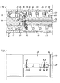
- the power wrench shown in the drawing figures comprises a housing 10 which at its rear end is provided with a connection piece 11 for a pressure air conduit by which motive air is supplied to a pneumatic vane motor (not shown).
- the pressure air supply to the motor is controlled by a throttle valve which is manoeuverable by a lever 12.
- the housing 10 is provided with an angle head 13 in which a square ended output shaft 14 is journalled.
- the power wrench further comprises a power transmission, not fully described in detail, by which the motor is coupled to the output shaft 14.
- the power transmission includes a torque limiting mechanism of a previously known type by which the torque delivery to the output shaft 14 is terminated as a certain torque level is reached.
- This mechanism comprises an override clutch 16 with cam means in the form of cam lobes 17 on the driven clutch half 18, conically ended rollers 19 disposed in pockets on the driving clutch half 20 and an axially displaceable thrust sleeve 21.
- the clutch 16 also comprises a compression spring 22 which is pretensioned between a thrust washer 23 on which the thrust sleeve 21 is axially supported and a support washer 24.
- the latter is backed by a ring 25 and a nut 26 which is threadingly mounted on a drive spindle 27.
- the drive spindle 27 is formed in one piece with the driving clutch half 20, and the nut 26 is formed with teeth 29 to be engaged by the teeth of a torque setting key to be introduced through an aperture 30 in the housing 10 and guided in a radial bore 31 in the ring 25.
- the torque limiting mechanism also comprises motive air shut-off means in the form of a shut-off valve (not shown) located in the air inlet passage, an activating rod 32, and a trip element 33 provided with a transverse bore 34.
- the activating rod 32 extends axially through the drive spindle 27 as well as through the motor and is axially supported on the trip element 33 in the operating condition of the tool, thereby maintaining the shut-off valve in open position.
- a slanted end portion 35 of the trip element 33 engages a conical inner surface 36 of the thrust sleeve 21 for camming action when the sleeve 21 is moved axially.
- the cam lobes 17 urge the conically ended rollers 19 outwardly, thereby causing an axial displacement of the thrust sleeve 21 against the action of the spring 22.
- the thrust sleeve 21 shifts the trip element 33 such that the acivating rod 32 falls into the bore 34, thereby causing closure of the throttle valve and a shut-off of the motor.
- the circumferential surfaces of the support washer 24 and the thrust washer 23 are edge shaped and form marks which are visible from outside the tool housing via the aperture 30 and a smaller aperture 38.
- a sleeve shaped gauge element 40 On a cylindrical waist portion 39 on the housing 10, there is movably supported a sleeve shaped gauge element 40.
- the latter is formed with a longitudinal slot 41 and carries at one edge of the slot 41 two axially spaced marks 42, 43.
- the distance between these two marks 42, 43 is chosen so as to correspond to that particular distance between the thrust washer 23 and the support washer 24, that in turn corresponds to a certain length of the spring 22 and, thereby, a desired basic setting of the torque limiting mechanism.
- Such a basic setting corresponds to a nominal output torque which is chosen within the available torque range of the tool with respect to the intended application of the tool.
- Setting of the nominal output torque of the tool is carried out by moving the gauge sleeve 40 so as to obtain alignment of the left hand mark 42 which the circumferential edge of the thrust washer 23. Then, without moving the sleeve 40, the support washer position is adjusted by a set key introduced through the aperture 30. When the mark edge of the support washer 24 is aligned with the right hand mark 43 on the sleeve 40, the basic setting is obtained.
- the embodiments of the invention are not limited to the shown and described example. Accordingly, the gauge element may be designed otherwise as may the marks on the support and thrust washers.
Landscapes
- Engineering & Computer Science (AREA)
- Mechanical Engineering (AREA)
- General Engineering & Computer Science (AREA)
- Details Of Spanners, Wrenches, And Screw Drivers And Accessories (AREA)
Applications Claiming Priority (2)
| Application Number | Priority Date | Filing Date | Title |
|---|---|---|---|
| SE9100473A SE9100473L (sv) | 1991-02-18 | 1991-02-18 | Kraftskruvdragare med justerbart momentstyrorgan |
| SE9100473 | 1991-02-18 |
Publications (2)
| Publication Number | Publication Date |
|---|---|
| EP0500511A1 true EP0500511A1 (de) | 1992-08-26 |
| EP0500511B1 EP0500511B1 (de) | 1995-04-26 |
Family
ID=20381923
Family Applications (1)
| Application Number | Title | Priority Date | Filing Date |
|---|---|---|---|
| EP92850027A Expired - Lifetime EP0500511B1 (de) | 1991-02-18 | 1992-02-11 | Kraftschrauber |
Country Status (5)
| Country | Link |
|---|---|
| US (1) | US5195406A (de) |
| EP (1) | EP0500511B1 (de) |
| JP (1) | JP3122686B2 (de) |
| DE (1) | DE69202174T2 (de) |
| SE (1) | SE9100473L (de) |
Families Citing this family (10)
| Publication number | Priority date | Publication date | Assignee | Title |
|---|---|---|---|---|
| US5738177A (en) * | 1995-07-28 | 1998-04-14 | Black & Decker Inc. | Production assembly tool |
| US6523442B2 (en) | 2000-12-07 | 2003-02-25 | Acradyne Inc. | Torque tool assembly |
| US6374706B1 (en) | 2001-01-25 | 2002-04-23 | Frederic M. Newman | Sucker rod tool |
| USD468173S1 (en) | 2001-10-03 | 2003-01-07 | Devilbiss Air Power Company | Pneumatic tool |
| TWM297820U (en) * | 2006-02-15 | 2006-09-21 | Tranmax Machinery Co Ltd | Open circuit controller of electric ratchet wrench |
| USD572554S1 (en) * | 2008-02-09 | 2008-07-08 | Tranmax Machinery Co., Ltd. | Electric handtool |
| CA2984320C (en) * | 2008-11-28 | 2019-09-03 | Key Energy Services, Inc. | Method and system for controlling tongs make-up speed and evaluating and controlling torque at the tongs |
| CA2686660C (en) * | 2008-11-28 | 2018-06-19 | Key Energy Services, Inc. | Method and system for monitoring the efficiency and health of a hydraulically driven system |
| US9289886B2 (en) | 2010-11-04 | 2016-03-22 | Milwaukee Electric Tool Corporation | Impact tool with adjustable clutch |
| JP2016055376A (ja) * | 2014-09-09 | 2016-04-21 | パナソニックIpマネジメント株式会社 | 電動工具 |
Citations (3)
| Publication number | Priority date | Publication date | Assignee | Title |
|---|---|---|---|---|
| US2777346A (en) * | 1954-06-21 | 1957-01-15 | Thomas P Walker | Predetermined torque release unit for wrenches and the like |
| US3262536A (en) * | 1964-05-26 | 1966-07-26 | Ingersoll Rand Co | Torque releasing clutch mechanism |
| FR1534520A (fr) * | 1967-08-22 | 1968-07-26 | Ingersoll Rand Co | Clé à moteur |
Family Cites Families (1)
| Publication number | Priority date | Publication date | Assignee | Title |
|---|---|---|---|---|
| SE461451B (sv) * | 1987-01-27 | 1990-02-19 | Atlas Copco Ab | Maskinverktyg foer tvaastegsdragning av skruvfoerband |
-
1991
- 1991-02-18 SE SE9100473A patent/SE9100473L/ not_active IP Right Cessation
-
1992
- 1992-02-11 DE DE69202174T patent/DE69202174T2/de not_active Expired - Fee Related
- 1992-02-11 EP EP92850027A patent/EP0500511B1/de not_active Expired - Lifetime
- 1992-02-12 US US07/834,633 patent/US5195406A/en not_active Expired - Fee Related
- 1992-02-18 JP JP04030474A patent/JP3122686B2/ja not_active Expired - Fee Related
Patent Citations (3)
| Publication number | Priority date | Publication date | Assignee | Title |
|---|---|---|---|---|
| US2777346A (en) * | 1954-06-21 | 1957-01-15 | Thomas P Walker | Predetermined torque release unit for wrenches and the like |
| US3262536A (en) * | 1964-05-26 | 1966-07-26 | Ingersoll Rand Co | Torque releasing clutch mechanism |
| FR1534520A (fr) * | 1967-08-22 | 1968-07-26 | Ingersoll Rand Co | Clé à moteur |
Also Published As
| Publication number | Publication date |
|---|---|
| SE9100473D0 (sv) | 1991-02-18 |
| SE466993B (sv) | 1992-05-11 |
| DE69202174T2 (de) | 1996-01-04 |
| DE69202174D1 (de) | 1995-06-01 |
| JP3122686B2 (ja) | 2001-01-09 |
| US5195406A (en) | 1993-03-23 |
| EP0500511B1 (de) | 1995-04-26 |
| SE9100473L (sv) | 1992-05-11 |
| JPH05208379A (ja) | 1993-08-20 |
Similar Documents
| Publication | Publication Date | Title |
|---|---|---|
| US4484871A (en) | Torque delivering tool with dual motor drive | |
| EP0500511B1 (de) | Kraftschrauber | |
| US2768546A (en) | Torque control for impact wrenches | |
| US5201374A (en) | Screw joint tightening power tool | |
| EP0625408B1 (de) | Impuls-Drehmomentschlüssel | |
| EP0900632B1 (de) | Pneumatisch angetriebener Schraubenschlüssel mit einstellbarer Auslassöffnung | |
| EP0080445B1 (de) | Doppelmotordrehmomenterzeugendes Gerät | |
| US4078618A (en) | Torque controller shutoff mechanism | |
| EP2632643B1 (de) | Pneumatischer drehmomentimpulsschlüssel mit gestufter abschaltfunktion | |
| US4429775A (en) | Clutch type torque control device for air driver | |
| US4576270A (en) | Torque control and fluid shutoff mechanism for a fluid operated tool | |
| GB1498968A (en) | Rotary power tool such as a power wrench | |
| EP0441758B1 (de) | Drehimpuls erzeugendes angetriebenes Werkzeug | |
| US3220526A (en) | One shot clutch | |
| EP0944458B1 (de) | Mit zwei trägheitskörpern versehenes drehimpuls-werkzeug mit antriebsabschaltung | |
| EP0390763A1 (de) | Motorbetriebener Schrauber | |
| US5167309A (en) | Torque Control clutch | |
| EP0665385A1 (de) | Momentenabhängiger Kupplungs-Freigabemechanismus | |
| EP0110725B1 (de) | Druckmittelbetriebenes Werkzeug | |
| EP0362989A1 (de) | Tragbares, kraftbetriebenes Gerät zum Entgraten von Rohrenden | |
| US3850553A (en) | Stall torque air shut-off control for pneumatic nut runners | |
| GB2260596A (en) | Valve construction for fluid-powered tool | |
| SE444277B (sv) | Verktyg for reffling av borrnings- eller andra halrumsytor i ett arbetsstycke | |
| GB1563219A (en) | Rotary air motors and pneumatically operated tools |
Legal Events
| Date | Code | Title | Description |
|---|---|---|---|
| PUAI | Public reference made under article 153(3) epc to a published international application that has entered the european phase |
Free format text: ORIGINAL CODE: 0009012 |
|
| AK | Designated contracting states |
Kind code of ref document: A1 Designated state(s): DE FR GB IT |
|
| 17P | Request for examination filed |
Effective date: 19930215 |
|
| 17Q | First examination report despatched |
Effective date: 19940705 |
|
| GRAA | (expected) grant |
Free format text: ORIGINAL CODE: 0009210 |
|
| AK | Designated contracting states |
Kind code of ref document: B1 Designated state(s): DE FR GB IT |
|
| REF | Corresponds to: |
Ref document number: 69202174 Country of ref document: DE Date of ref document: 19950601 |
|
| ITF | It: translation for a ep patent filed | ||
| ET | Fr: translation filed | ||
| PLBE | No opposition filed within time limit |
Free format text: ORIGINAL CODE: 0009261 |
|
| 26N | No opposition filed | ||
| PGFP | Annual fee paid to national office [announced via postgrant information from national office to epo] |
Ref country code: DE Payment date: 20010205 Year of fee payment: 10 |
|
| PGFP | Annual fee paid to national office [announced via postgrant information from national office to epo] |
Ref country code: GB Payment date: 20010207 Year of fee payment: 10 |
|
| PGFP | Annual fee paid to national office [announced via postgrant information from national office to epo] |
Ref country code: FR Payment date: 20010213 Year of fee payment: 10 |
|
| REG | Reference to a national code |
Ref country code: GB Ref legal event code: IF02 |
|
| PG25 | Lapsed in a contracting state [announced via postgrant information from national office to epo] |
Ref country code: GB Free format text: LAPSE BECAUSE OF NON-PAYMENT OF DUE FEES Effective date: 20020211 |
|
| PG25 | Lapsed in a contracting state [announced via postgrant information from national office to epo] |
Ref country code: DE Free format text: LAPSE BECAUSE OF NON-PAYMENT OF DUE FEES Effective date: 20020903 |
|
| GBPC | Gb: european patent ceased through non-payment of renewal fee |
Effective date: 20020211 |
|
| PG25 | Lapsed in a contracting state [announced via postgrant information from national office to epo] |
Ref country code: FR Free format text: LAPSE BECAUSE OF NON-PAYMENT OF DUE FEES Effective date: 20021031 |
|
| REG | Reference to a national code |
Ref country code: FR Ref legal event code: ST |
|
| PG25 | Lapsed in a contracting state [announced via postgrant information from national office to epo] |
Ref country code: IT Free format text: LAPSE BECAUSE OF NON-PAYMENT OF DUE FEES Effective date: 20050211 |