EP0500517A1 - Procédé pour mettre en route une installation pour la production de fonte ou de prématériau d'acier et installation pour sa mise en oeuvre - Google Patents
Procédé pour mettre en route une installation pour la production de fonte ou de prématériau d'acier et installation pour sa mise en oeuvre Download PDFInfo
- Publication number
- EP0500517A1 EP0500517A1 EP92890037A EP92890037A EP0500517A1 EP 0500517 A1 EP0500517 A1 EP 0500517A1 EP 92890037 A EP92890037 A EP 92890037A EP 92890037 A EP92890037 A EP 92890037A EP 0500517 A1 EP0500517 A1 EP 0500517A1
- Authority
- EP
- European Patent Office
- Prior art keywords
- shaft furnace
- gas
- reduction shaft
- coke
- direct reduction
- Prior art date
- Legal status (The legal status is an assumption and is not a legal conclusion. Google has not performed a legal analysis and makes no representation as to the accuracy of the status listed.)
- Granted
Links
Images


Classifications
-
- C—CHEMISTRY; METALLURGY
- C21—METALLURGY OF IRON
- C21B—MANUFACTURE OF IRON OR STEEL
- C21B13/00—Making spongy iron or liquid steel, by direct processes
- C21B13/0006—Making spongy iron or liquid steel, by direct processes obtaining iron or steel in a molten state
- C21B13/0013—Making spongy iron or liquid steel, by direct processes obtaining iron or steel in a molten state introduction of iron oxide into a bath of molten iron containing a carbon reductant
- C21B13/002—Reduction of iron ores by passing through a heated column of carbon
-
- C—CHEMISTRY; METALLURGY
- C21—METALLURGY OF IRON
- C21B—MANUFACTURE OF IRON OR STEEL
- C21B13/00—Making spongy iron or liquid steel, by direct processes
- C21B13/0073—Selection or treatment of the reducing gases
-
- C—CHEMISTRY; METALLURGY
- C21—METALLURGY OF IRON
- C21B—MANUFACTURE OF IRON OR STEEL
- C21B13/00—Making spongy iron or liquid steel, by direct processes
- C21B13/02—Making spongy iron or liquid steel, by direct processes in shaft furnaces
- C21B13/023—Making spongy iron or liquid steel, by direct processes in shaft furnaces wherein iron or steel is obtained in a molten state
-
- C—CHEMISTRY; METALLURGY
- C21—METALLURGY OF IRON
- C21B—MANUFACTURE OF IRON OR STEEL
- C21B13/00—Making spongy iron or liquid steel, by direct processes
- C21B13/14—Multi-stage processes processes carried out in different vessels or furnaces
-
- F—MECHANICAL ENGINEERING; LIGHTING; HEATING; WEAPONS; BLASTING
- F27—FURNACES; KILNS; OVENS; RETORTS
- F27D—DETAILS OR ACCESSORIES OF FURNACES, KILNS, OVENS OR RETORTS, IN SO FAR AS THEY ARE OF KINDS OCCURRING IN MORE THAN ONE KIND OF FURNACE
- F27D17/00—Arrangements for using waste heat; Arrangements for using, or disposing of, waste gases
- F27D17/10—Arrangements for using waste heat
-
- C—CHEMISTRY; METALLURGY
- C21—METALLURGY OF IRON
- C21B—MANUFACTURE OF IRON OR STEEL
- C21B2100/00—Handling of exhaust gases produced during the manufacture of iron or steel
- C21B2100/60—Process control or energy utilisation in the manufacture of iron or steel
- C21B2100/66—Heat exchange
Definitions
- the invention relates to a method for starting up a plant for the production of pig iron or steel raw material, in which production particulate feedstocks are reduced in a direct reduction shaft furnace by a reducing gas, the sponge iron particles obtained are melted down in a melter gasifier with the addition of carbon carriers and oxygen-containing gas with simultaneous formation of the reducing gas, and the reducing gas is introduced into the direct reduction shaft furnace, and a plant for carrying out the process.
- the gasification temperature is approx. 2,000 ° C
- the temperature in the bottom area of the melter is approx. 1,500 ° C
- the temperature in the area of the tap openings for slag and pig iron is at least 1,350 ° C.
- the invention has for its object to provide a method for commissioning a plant for the production of pig iron or steel raw material according to the type described above, with which high, in particular the above-mentioned temperatures in the melter gasifier and sufficient heating of the direct reduction shaft furnace can be achieved.
- a gas pipeline made of a material melting at about the melting temperature of the pig iron, preferably made of steel, is provided, which protrudes with a connector through a side wall opening of the melter gasifier.
- the height of the heating burner can be attached to and removed from the melting gasifier in the first third of the melting gasifier.
- FIG. 1 shows a plant for the production of pig iron in a schematic representation in the operating state
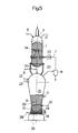
- FIGS. 2 to 5 show this plant after each process step carried out to start up the plant.
- the shaft furnace 1 designates a direct reduction shaft furnace, in the direct reduction zone 2 of which 3 pieces of iron oxide-containing feedstocks 4 are charged from above via a feed line, optionally together with unburned aggregates introduced via a feed line 5.
- the shaft furnace 1 stands with a smelting ver Gas 6 in connection, in which a reducing gas is generated from carbon carriers and oxygen-containing gas, which is fed to the shaft furnace 1 via a feed line 7, a gas cleaning and a gas cooling device 8 being provided in the feed line 7.
- the melter gasifier 6 has a feed 9 for solid, lumpy carbon carriers, optionally a plurality of feed lines 10, 11 for oxygen-containing gases and feed lines 12, 13 for carbon carriers which are liquid or gaseous at room temperature, such as hydrocarbons, and for burnt additives.
- Molten pig iron 16 and molten slag 17 collect in the meltdown gasifier 6 below the meltdown gasification zone 15 and are tapped separately by means of their own tapping 18, 19.
- the lumpy ore reduced to sponge iron in shaft furnace 1 in direct reduction zone 2 is fed together with the aggregates burned in direct reduction zone 2 via shaft furnace 1 to lines 20 connecting melter gasifier 6, for example by means of discharge screws (not shown).
- At the upper part of the shaft furnace 1 there is a discharge line 21 for the top gas arising in the direct reduction zone 2.
- a valve 22 designed as a gas shut-off valve is provided in each feed line 7.
- external heating burners (25) which can be operated with coke gas or natural gas are provided . These heating burners are only in operation during heating and can be removed from the melter 6 after the system has been started up.
- a gas pipeline 26 is introduced into the still cold and empty melter gasifier 6 (see FIG. 2).
- This raw gas line 26 is placed on the bottom 27 of the melter 6 and opens at one point through a side wall opening of the melter 6 with a connector 28 to the outside.
- the gas pipeline 26 is made of steel pipes, which are provided with gas outlet openings 29 on their upper side, and extends in several concentric rings or in the form of a fan evenly over approximately the entire floor area. The function of this gas pipe 26 is explained in more detail later with reference to FIG. 3.
- the heating burners 25 are put into operation.
- the resulting flue gases 30 heat the refractory lining of the empty melter 6 in accordance with the heating conditions and flow via the feed lines 7, whose gas shut-off valves are in the open position, and via the lines 20 into the still empty direct reduction shaft furnace 1 and also dry and heat this. This situation is shown in Fig. 2.
- coke 31 or a degassed coal product such as e.g. B. broken electrodes or petroleum coke
- the amount of coke 31 corresponds approximately to the volume of the lower, cylindrical part 23 of the melter gasifier 6.
- the gas shut-off valves 22 are closed. The flue gases then flow 100% through the lines 20 and heat the coke 31 to the ignition temperature, which is approximately 650 ° C.
- the coke 31 is brought into the melter 6 via the lines 20.
- air 32 or oxygen is introduced through the gas pipeline 26, causing the coke 31 to ignite and burn.
- Temperatures of about 1,200 ° to 1,500 ° C. arise in the process. This situation is shown in FIG. 4.
- the heating burners 25 are switched off and removed (FIG. 5). This high temperature ensures the molten state of the slag 17 and the pig iron 16 during the subsequent melting operation.
- the fine coke or fine coal 33 is brought to ignition temperature by further blowing in ground air via the gas pipeline 26, and it starts after the start-up of the Supply lines 10 and 11 and optionally the lines 12, 13 the gasification in the melter 6 in a conventional manner.
- start-up oil 34 which contains HO slag, possibly sponge iron, aggregates (lime, dolomite), possibly flux (CaF 2 ) and ores, begins in the direct reduction shaft furnace 1.
- the resulting in the gasification in the melter 6 reducing gases are introduced after opening the gas shut-off valves 22 via the supply lines 7 in a known manner for ore reduction in the direct reduction shaft furnace 1.
- the gas pipeline 26 is shut off, the end of this line protruding through the side wall opening pushes into the interior of the melter gasifier 6 and the side wall opening is closed.
- the gas pipeline 26 melts, so that there is no impairment of the melting operation.
Landscapes
- Engineering & Computer Science (AREA)
- Chemical & Material Sciences (AREA)
- Manufacturing & Machinery (AREA)
- Materials Engineering (AREA)
- Metallurgy (AREA)
- Organic Chemistry (AREA)
- Environmental & Geological Engineering (AREA)
- Mechanical Engineering (AREA)
- General Engineering & Computer Science (AREA)
- Manufacture Of Iron (AREA)
- Vertical, Hearth, Or Arc Furnaces (AREA)
Applications Claiming Priority (2)
| Application Number | Priority Date | Filing Date | Title |
|---|---|---|---|
| AT348/91 | 1991-02-19 | ||
| AT0034891A AT395435B (de) | 1991-02-19 | 1991-02-19 | Verfahren zur inbetriebnahme einer anlage zur herstellung von roheisen oder stahlvormaterial, sowie anlage zur durchfuehrung des verfahrens |
Publications (2)
| Publication Number | Publication Date |
|---|---|
| EP0500517A1 true EP0500517A1 (fr) | 1992-08-26 |
| EP0500517B1 EP0500517B1 (fr) | 1996-06-26 |
Family
ID=3488231
Family Applications (1)
| Application Number | Title | Priority Date | Filing Date |
|---|---|---|---|
| EP92890037A Expired - Lifetime EP0500517B1 (fr) | 1991-02-19 | 1992-02-13 | Procédé pour mettre en route une installation pour la production de fonte ou de prématériau d'acier et installation pour sa mise en oeuvre |
Country Status (12)
| Country | Link |
|---|---|
| US (1) | US5226951A (fr) |
| EP (1) | EP0500517B1 (fr) |
| JP (1) | JPH0676611B2 (fr) |
| KR (1) | KR950006689B1 (fr) |
| CN (1) | CN1025872C (fr) |
| AT (1) | AT395435B (fr) |
| AU (1) | AU634436B2 (fr) |
| BR (1) | BR9200547A (fr) |
| CA (1) | CA2061147C (fr) |
| DE (1) | DE59206631D1 (fr) |
| ES (1) | ES2091451T3 (fr) |
| ZA (1) | ZA921198B (fr) |
Cited By (1)
| Publication number | Priority date | Publication date | Assignee | Title |
|---|---|---|---|---|
| DE102012112182A1 (de) | 2012-12-12 | 2014-06-12 | Thyssenkrupp Uhde Gmbh | Verfahren zum Aufheizen eines Hochtemperatur-Winkler-Vergasers |
Families Citing this family (4)
| Publication number | Priority date | Publication date | Assignee | Title |
|---|---|---|---|---|
| AUPN639995A0 (en) | 1995-11-03 | 1995-11-30 | Technological Resources Pty Limited | A method and an apparatus for producing metals and metal alloys |
| AUPO276496A0 (en) | 1996-10-07 | 1996-10-31 | Technological Resources Pty Limited | A method and an apparatus for producing metals and metal alloys |
| AT405650B (de) * | 1996-10-08 | 1999-10-25 | Voest Alpine Ind Anlagen | Verfahren zum einblasen von metalloxidhältigen feinteilchen in ein reduktionsgas |
| EP3239306A1 (fr) * | 2016-04-27 | 2017-11-01 | Primetals Technologies Austria GmbH | Procédé et appareil de fabrication de produits de fonte brute liquide |
Citations (2)
| Publication number | Priority date | Publication date | Assignee | Title |
|---|---|---|---|---|
| DE3727146C1 (de) * | 1987-08-14 | 1988-09-22 | Rheinische Braunkohlenw Ag | Verfahren zum Anfahren eines Vergasers |
| EP0316299A2 (fr) * | 1987-11-12 | 1989-05-17 | Deutsche Voest-Alpine Industrieanlagenbau Gmbh | Procédé pour dézinguer le flux de matières pendant l'opération d'une installation pour la production de la fonte brute |
Family Cites Families (7)
| Publication number | Priority date | Publication date | Assignee | Title |
|---|---|---|---|---|
| US4053301A (en) * | 1975-10-14 | 1977-10-11 | Hazen Research, Inc. | Process for the direct production of steel |
| US4244732A (en) * | 1979-03-27 | 1981-01-13 | Kaiser Engineers, Inc. | Manufacture of steel from ores containing high phosphorous and other undesirable constituents |
| DE3034539C2 (de) * | 1980-09-12 | 1982-07-22 | Korf-Stahl Ag, 7570 Baden-Baden | Verfahren und Vorrichtung zur direkten Erzeugung von flüssigem Roheisen aus stückigem Eisenerz |
| DE3438487A1 (de) * | 1984-10-17 | 1986-04-24 | Korf Engineering GmbH, 4000 Düsseldorf | Verfahren zur herstellung von roheisen |
| AT387403B (de) * | 1987-06-15 | 1989-01-25 | Voest Alpine Ag | Verfahren und anlage zur herstellung von fluessigem roheisen oder stahlvorprodukten aus stueckigen, eisenerzhaeltigen einsatzstoffen |
| AT389124B (de) * | 1987-09-17 | 1989-10-25 | Voest Alpine Ag | Verfahren und anlage zur herstellung von fluessigem roheisen oder stahlvorprodukten aus stueckigen, eisenerzhaeltigen einsatzstoffen |
| DE3742156C1 (de) * | 1987-12-10 | 1988-10-13 | Korf Engineering Gmbh | Verfahren zum Betrieb eines Einschmelzvergasers und Einschmelzvergaser zu dessen Durchfuehrung |
-
1991
- 1991-02-19 AT AT0034891A patent/AT395435B/de not_active IP Right Cessation
-
1992
- 1992-02-07 AU AU10843/92A patent/AU634436B2/en not_active Ceased
- 1992-02-13 EP EP92890037A patent/EP0500517B1/fr not_active Expired - Lifetime
- 1992-02-13 CA CA002061147A patent/CA2061147C/fr not_active Expired - Fee Related
- 1992-02-13 ES ES92890037T patent/ES2091451T3/es not_active Expired - Lifetime
- 1992-02-13 DE DE59206631T patent/DE59206631D1/de not_active Expired - Fee Related
- 1992-02-18 KR KR1019920002350A patent/KR950006689B1/ko not_active Expired - Fee Related
- 1992-02-18 CN CN92101116A patent/CN1025872C/zh not_active Expired - Fee Related
- 1992-02-19 BR BR929200547A patent/BR9200547A/pt not_active IP Right Cessation
- 1992-02-19 ZA ZA921198A patent/ZA921198B/xx unknown
- 1992-02-19 JP JP4031868A patent/JPH0676611B2/ja not_active Expired - Lifetime
- 1992-02-19 US US07/837,757 patent/US5226951A/en not_active Expired - Lifetime
Patent Citations (2)
| Publication number | Priority date | Publication date | Assignee | Title |
|---|---|---|---|---|
| DE3727146C1 (de) * | 1987-08-14 | 1988-09-22 | Rheinische Braunkohlenw Ag | Verfahren zum Anfahren eines Vergasers |
| EP0316299A2 (fr) * | 1987-11-12 | 1989-05-17 | Deutsche Voest-Alpine Industrieanlagenbau Gmbh | Procédé pour dézinguer le flux de matières pendant l'opération d'une installation pour la production de la fonte brute |
Cited By (1)
| Publication number | Priority date | Publication date | Assignee | Title |
|---|---|---|---|---|
| DE102012112182A1 (de) | 2012-12-12 | 2014-06-12 | Thyssenkrupp Uhde Gmbh | Verfahren zum Aufheizen eines Hochtemperatur-Winkler-Vergasers |
Also Published As
| Publication number | Publication date |
|---|---|
| JPH0676611B2 (ja) | 1994-09-28 |
| KR930018038A (ko) | 1993-09-21 |
| AU634436B2 (en) | 1993-02-18 |
| US5226951A (en) | 1993-07-13 |
| AT395435B (de) | 1992-12-28 |
| ES2091451T3 (es) | 1996-11-01 |
| DE59206631D1 (de) | 1996-08-01 |
| ZA921198B (en) | 1992-11-25 |
| CN1025872C (zh) | 1994-09-07 |
| KR950006689B1 (ko) | 1995-06-21 |
| CA2061147A1 (fr) | 1992-08-20 |
| ATA34891A (de) | 1992-05-15 |
| JPH04318110A (ja) | 1992-11-09 |
| CN1064316A (zh) | 1992-09-09 |
| CA2061147C (fr) | 1997-08-26 |
| BR9200547A (pt) | 1992-10-27 |
| EP0500517B1 (fr) | 1996-06-26 |
| AU1084392A (en) | 1992-08-27 |
Similar Documents
| Publication | Publication Date | Title |
|---|---|---|
| EP0126391B1 (fr) | Procédé de production de fer | |
| DE3875616T2 (de) | Schmelzofen. | |
| DE2428891C3 (de) | Schachtofen zum Schmelzen von mineralischen Substanzen zur Herstellung von Mineralwolle | |
| EP0182775A2 (fr) | Procédé pour la production de la fonte liquide ou des ébauches en acier ainsi que dispositif pour la mise en oeuvre de ce procédé | |
| DE4339675C1 (de) | Verfahren und Vorrichtung zum Einschmelzen von festen Verbrennungsrückständen | |
| EP0796349B1 (fr) | Procede et installation de production d'eponge de fer | |
| EP0500517B1 (fr) | Procédé pour mettre en route une installation pour la production de fonte ou de prématériau d'acier et installation pour sa mise en oeuvre | |
| DE19640497A1 (de) | Koksbeheizter Kreislaufgaskupolofen zur stofflichen und/oder energetischen Verwertung von Abfallmaterialien | |
| DE3219984C2 (fr) | ||
| EP1583811B1 (fr) | Gazeificateur a fusion en cuve et procede de traitement thermique et de valorisation de dechets | |
| DE3136321C2 (de) | Kalzinierofen zum Brennen von Kalkstein und ähnlichen mineralischen Rohstoffen | |
| DE2729983C3 (fr) | ||
| EP0521523B1 (fr) | Procédé de conduite d'un cubilot | |
| DE2747571A1 (de) | Verfahren zum kontinuierlichen erzeugen eines reduktionsgases und vorrichtung zum durchfuehren des verfahrens | |
| DE3324064C2 (fr) | ||
| DE4324699C2 (de) | Verfahren und Einrichtung zur vollständigen Nachverbrennung von Prozeßgasen in einem koksbeheizten Schachtofen | |
| DE2001563C3 (de) | Drehrohrofen zur thermischen Behandlung von Feststoffen und Verfahren zum Betreiben des Drehrohrofens | |
| DE2552392A1 (de) | Verfahren zum zufuehren von waermeenergie an eisenschmelzen | |
| DE29603480U1 (de) | Schmelz- und Verbrennungsaggregat zur Verschlackung und/oder Verglasung von schadstoffbehafteten Reststoffen | |
| DE102004045926B4 (de) | Entsorgungsaggregat | |
| DE3526291C2 (fr) | ||
| DE19616677C2 (de) | Herd-Schacht-Ofen zur Reststoffverwertung | |
| EP1095235A2 (fr) | Cubilot a circulation de gaz chauffe au coke pour la valorisation materielle et/ou energetique de materiaux de dechets de differentes compositions | |
| DE2014339C (de) | Verfahren zur Herstellung von Stahl durch Reduktion und Schmelzen von Eisen erz und Schrott in einem Tandemofen | |
| DE2426250C3 (de) | Verfahren zur Herstellung einer Schmelze aus Oxyden |
Legal Events
| Date | Code | Title | Description |
|---|---|---|---|
| PUAI | Public reference made under article 153(3) epc to a published international application that has entered the european phase |
Free format text: ORIGINAL CODE: 0009012 |
|
| AK | Designated contracting states |
Kind code of ref document: A1 Designated state(s): BE DE ES FR GB IT LU NL PT SE |
|
| 17P | Request for examination filed |
Effective date: 19930206 |
|
| 17Q | First examination report despatched |
Effective date: 19940928 |
|
| GRAH | Despatch of communication of intention to grant a patent |
Free format text: ORIGINAL CODE: EPIDOS IGRA |
|
| GRAH | Despatch of communication of intention to grant a patent |
Free format text: ORIGINAL CODE: EPIDOS IGRA |
|
| RAP1 | Party data changed (applicant data changed or rights of an application transferred) |
Owner name: DEUTSCHE VOEST-ALPINE INDUSTRIEANLAGENBAU GMBH |
|
| GRAA | (expected) grant |
Free format text: ORIGINAL CODE: 0009210 |
|
| AK | Designated contracting states |
Kind code of ref document: B1 Designated state(s): BE DE ES FR GB IT LU NL PT SE |
|
| REF | Corresponds to: |
Ref document number: 59206631 Country of ref document: DE Date of ref document: 19960801 |
|
| ITF | It: translation for a ep patent filed | ||
| ET | Fr: translation filed | ||
| GBT | Gb: translation of ep patent filed (gb section 77(6)(a)/1977) |
Effective date: 19960830 |
|
| REG | Reference to a national code |
Ref country code: ES Ref legal event code: FG2A Ref document number: 2091451 Country of ref document: ES Kind code of ref document: T3 |
|
| SC4A | Pt: translation is available |
Free format text: 960827 AVAILABILITY OF NATIONAL TRANSLATION |
|
| PLBE | No opposition filed within time limit |
Free format text: ORIGINAL CODE: 0009261 |
|
| 26N | No opposition filed | ||
| PGFP | Annual fee paid to national office [announced via postgrant information from national office to epo] |
Ref country code: PT Payment date: 20001219 Year of fee payment: 10 |
|
| PGFP | Annual fee paid to national office [announced via postgrant information from national office to epo] |
Ref country code: FR Payment date: 20001220 Year of fee payment: 10 |
|
| PGFP | Annual fee paid to national office [announced via postgrant information from national office to epo] |
Ref country code: BE Payment date: 20001228 Year of fee payment: 10 |
|
| PGFP | Annual fee paid to national office [announced via postgrant information from national office to epo] |
Ref country code: GB Payment date: 20010213 Year of fee payment: 10 |
|
| PGFP | Annual fee paid to national office [announced via postgrant information from national office to epo] |
Ref country code: ES Payment date: 20010216 Year of fee payment: 10 |
|
| PGFP | Annual fee paid to national office [announced via postgrant information from national office to epo] |
Ref country code: SE Payment date: 20010227 Year of fee payment: 10 |
|
| PGFP | Annual fee paid to national office [announced via postgrant information from national office to epo] |
Ref country code: NL Payment date: 20010228 Year of fee payment: 10 |
|
| REG | Reference to a national code |
Ref country code: GB Ref legal event code: IF02 |
|
| PG25 | Lapsed in a contracting state [announced via postgrant information from national office to epo] |
Ref country code: GB Free format text: LAPSE BECAUSE OF NON-PAYMENT OF DUE FEES Effective date: 20020213 |
|
| PG25 | Lapsed in a contracting state [announced via postgrant information from national office to epo] |
Ref country code: SE Free format text: LAPSE BECAUSE OF NON-PAYMENT OF DUE FEES Effective date: 20020214 Ref country code: ES Free format text: LAPSE BECAUSE OF NON-PAYMENT OF DUE FEES Effective date: 20020214 |
|
| PG25 | Lapsed in a contracting state [announced via postgrant information from national office to epo] |
Ref country code: BE Free format text: LAPSE BECAUSE OF NON-PAYMENT OF DUE FEES Effective date: 20020228 |
|
| BERE | Be: lapsed |
Owner name: DEUTSCHE VOEST-ALPINE INDUSTRIEANLAGENBAU G.M.B.H Effective date: 20020228 |
|
| PG25 | Lapsed in a contracting state [announced via postgrant information from national office to epo] |
Ref country code: PT Free format text: LAPSE BECAUSE OF NON-PAYMENT OF DUE FEES Effective date: 20020831 |
|
| PG25 | Lapsed in a contracting state [announced via postgrant information from national office to epo] |
Ref country code: NL Free format text: LAPSE BECAUSE OF NON-PAYMENT OF DUE FEES Effective date: 20020901 |
|
| EUG | Se: european patent has lapsed |
Ref document number: 92890037.2 |
|
| GBPC | Gb: european patent ceased through non-payment of renewal fee |
Effective date: 20020213 |
|
| PG25 | Lapsed in a contracting state [announced via postgrant information from national office to epo] |
Ref country code: FR Free format text: LAPSE BECAUSE OF NON-PAYMENT OF DUE FEES Effective date: 20021031 |
|
| NLV4 | Nl: lapsed or anulled due to non-payment of the annual fee |
Effective date: 20020901 |
|
| REG | Reference to a national code |
Ref country code: PT Ref legal event code: MM4A Free format text: LAPSE DUE TO NON-PAYMENT OF FEES Effective date: 20020831 |
|
| REG | Reference to a national code |
Ref country code: FR Ref legal event code: ST |
|
| REG | Reference to a national code |
Ref country code: ES Ref legal event code: FD2A Effective date: 20031022 |
|
| PG25 | Lapsed in a contracting state [announced via postgrant information from national office to epo] |
Ref country code: IT Free format text: LAPSE BECAUSE OF NON-PAYMENT OF DUE FEES;WARNING: LAPSES OF ITALIAN PATENTS WITH EFFECTIVE DATE BEFORE 2007 MAY HAVE OCCURRED AT ANY TIME BEFORE 2007. THE CORRECT EFFECTIVE DATE MAY BE DIFFERENT FROM THE ONE RECORDED. Effective date: 20050213 |
|
| PGFP | Annual fee paid to national office [announced via postgrant information from national office to epo] |
Ref country code: DE Payment date: 20070420 Year of fee payment: 16 |
|
| PGFP | Annual fee paid to national office [announced via postgrant information from national office to epo] |
Ref country code: LU Payment date: 20080212 Year of fee payment: 17 |
|
| PG25 | Lapsed in a contracting state [announced via postgrant information from national office to epo] |
Ref country code: DE Free format text: LAPSE BECAUSE OF NON-PAYMENT OF DUE FEES Effective date: 20080902 |
|
| PG25 | Lapsed in a contracting state [announced via postgrant information from national office to epo] |
Ref country code: LU Free format text: LAPSE BECAUSE OF NON-PAYMENT OF DUE FEES Effective date: 20090213 |