EP0500537B1 - Elektrische zahnbürste mit lösbarem bürstenteil - Google Patents
Elektrische zahnbürste mit lösbarem bürstenteil Download PDFInfo
- Publication number
- EP0500537B1 EP0500537B1 EP90912750A EP90912750A EP0500537B1 EP 0500537 B1 EP0500537 B1 EP 0500537B1 EP 90912750 A EP90912750 A EP 90912750A EP 90912750 A EP90912750 A EP 90912750A EP 0500537 B1 EP0500537 B1 EP 0500537B1
- Authority
- EP
- European Patent Office
- Prior art keywords
- shaft
- drive shaft
- electric toothbrush
- section
- brush
- Prior art date
- Legal status (The legal status is an assumption and is not a legal conclusion. Google has not performed a legal analysis and makes no representation as to the accuracy of the status listed.)
- Expired - Lifetime
Links
- 238000010168 coupling process Methods 0.000 claims description 36
- 230000008878 coupling Effects 0.000 claims description 31
- 238000005859 coupling reaction Methods 0.000 claims description 31
- 230000000295 complement effect Effects 0.000 claims description 4
- 230000007704 transition Effects 0.000 claims description 4
- 238000003780 insertion Methods 0.000 description 5
- 230000037431 insertion Effects 0.000 description 5
- 230000008901 benefit Effects 0.000 description 4
- 230000005540 biological transmission Effects 0.000 description 4
- 230000006378 damage Effects 0.000 description 3
- 230000000694 effects Effects 0.000 description 3
- 229920006351 engineering plastic Polymers 0.000 description 3
- 238000002347 injection Methods 0.000 description 3
- 239000007924 injection Substances 0.000 description 3
- 239000000463 material Substances 0.000 description 3
- 238000000926 separation method Methods 0.000 description 3
- 208000027418 Wounds and injury Diseases 0.000 description 2
- 238000006073 displacement reaction Methods 0.000 description 2
- 208000014674 injury Diseases 0.000 description 2
- 230000003213 activating effect Effects 0.000 description 1
- 230000015572 biosynthetic process Effects 0.000 description 1
- 230000008859 change Effects 0.000 description 1
- 239000007822 coupling agent Substances 0.000 description 1
- 238000004519 manufacturing process Methods 0.000 description 1
- 230000000149 penetrating effect Effects 0.000 description 1
- 229920003023 plastic Polymers 0.000 description 1
- 239000004033 plastic Substances 0.000 description 1
- 239000007779 soft material Substances 0.000 description 1
- 229910001220 stainless steel Inorganic materials 0.000 description 1
- 239000010935 stainless steel Substances 0.000 description 1
- 230000008719 thickening Effects 0.000 description 1
Images


Classifications
-
- A—HUMAN NECESSITIES
- A61—MEDICAL OR VETERINARY SCIENCE; HYGIENE
- A61C—DENTISTRY; APPARATUS OR METHODS FOR ORAL OR DENTAL HYGIENE
- A61C17/00—Devices for cleaning, polishing, rinsing or drying teeth, teeth cavities or prostheses; Saliva removers; Dental appliances for receiving spittle
- A61C17/16—Power-driven cleaning or polishing devices
- A61C17/22—Power-driven cleaning or polishing devices with brushes, cushions, cups, or the like
- A61C17/222—Brush body details, e.g. the shape thereof or connection to handle
-
- A—HUMAN NECESSITIES
- A61—MEDICAL OR VETERINARY SCIENCE; HYGIENE
- A61C—DENTISTRY; APPARATUS OR METHODS FOR ORAL OR DENTAL HYGIENE
- A61C17/00—Devices for cleaning, polishing, rinsing or drying teeth, teeth cavities or prostheses; Saliva removers; Dental appliances for receiving spittle
- A61C17/16—Power-driven cleaning or polishing devices
- A61C17/22—Power-driven cleaning or polishing devices with brushes, cushions, cups, or the like
- A61C17/32—Power-driven cleaning or polishing devices with brushes, cushions, cups, or the like reciprocating or oscillating
- A61C17/34—Power-driven cleaning or polishing devices with brushes, cushions, cups, or the like reciprocating or oscillating driven by electric motor
- A61C17/3409—Power-driven cleaning or polishing devices with brushes, cushions, cups, or the like reciprocating or oscillating driven by electric motor characterized by the movement of the brush body
- A61C17/3436—Rotation around the axis perpendicular to the plane defined by the bristle holder
-
- Y—GENERAL TAGGING OF NEW TECHNOLOGICAL DEVELOPMENTS; GENERAL TAGGING OF CROSS-SECTIONAL TECHNOLOGIES SPANNING OVER SEVERAL SECTIONS OF THE IPC; TECHNICAL SUBJECTS COVERED BY FORMER USPC CROSS-REFERENCE ART COLLECTIONS [XRACs] AND DIGESTS
- Y10—TECHNICAL SUBJECTS COVERED BY FORMER USPC
- Y10T—TECHNICAL SUBJECTS COVERED BY FORMER US CLASSIFICATION
- Y10T403/00—Joints and connections
- Y10T403/57—Distinct end coupler
- Y10T403/5761—Interrupted periphery, e.g., split or segmental, etc.
- Y10T403/5786—Split
-
- Y—GENERAL TAGGING OF NEW TECHNOLOGICAL DEVELOPMENTS; GENERAL TAGGING OF CROSS-SECTIONAL TECHNOLOGIES SPANNING OVER SEVERAL SECTIONS OF THE IPC; TECHNICAL SUBJECTS COVERED BY FORMER USPC CROSS-REFERENCE ART COLLECTIONS [XRACs] AND DIGESTS
- Y10—TECHNICAL SUBJECTS COVERED BY FORMER USPC
- Y10T—TECHNICAL SUBJECTS COVERED BY FORMER US CLASSIFICATION
- Y10T403/00—Joints and connections
- Y10T403/57—Distinct end coupler
- Y10T403/5793—Distinct end coupler including member wedging or camming means
-
- Y—GENERAL TAGGING OF NEW TECHNOLOGICAL DEVELOPMENTS; GENERAL TAGGING OF CROSS-SECTIONAL TECHNOLOGIES SPANNING OVER SEVERAL SECTIONS OF THE IPC; TECHNICAL SUBJECTS COVERED BY FORMER USPC CROSS-REFERENCE ART COLLECTIONS [XRACs] AND DIGESTS
- Y10—TECHNICAL SUBJECTS COVERED BY FORMER USPC
- Y10T—TECHNICAL SUBJECTS COVERED BY FORMER US CLASSIFICATION
- Y10T403/00—Joints and connections
- Y10T403/60—Biased catch or latch
-
- Y—GENERAL TAGGING OF NEW TECHNOLOGICAL DEVELOPMENTS; GENERAL TAGGING OF CROSS-SECTIONAL TECHNOLOGIES SPANNING OVER SEVERAL SECTIONS OF THE IPC; TECHNICAL SUBJECTS COVERED BY FORMER USPC CROSS-REFERENCE ART COLLECTIONS [XRACs] AND DIGESTS
- Y10—TECHNICAL SUBJECTS COVERED BY FORMER USPC
- Y10T—TECHNICAL SUBJECTS COVERED BY FORMER US CLASSIFICATION
- Y10T403/00—Joints and connections
- Y10T403/70—Interfitted members
- Y10T403/7075—Interfitted members including discrete retainer
- Y10T403/7077—Interfitted members including discrete retainer for telescoping members
Definitions
- the invention relates to an electric toothbrush consisting of a handle part with an electric motor drive and a drive shaft and a brush part with a shaft for driving a rotatable bristle holder and a housing for receiving the shaft and for mounting the bristle holder.
- the brush part can be connected to the handle part via coupling means for fixing the brush part to the handle part and the drive shaft can be coupled to the shaft via coupling means, coupling means which are assigned to the housing of the brush part and the handle part interacting.
- the fixing of the brush part on the handle part in the axial and radial direction is thus carried out by a single coupling means.
- This arrangement proves disadvantageous in that tolerances in the positioning of the parts to be coupled, namely the handle part and the housing part, and the drive shaft and the shaft in the housing part, are not without further can be compensated. If the drive shaft and the shaft of the brush part are not exactly aligned, it is practically impossible to couple the brush part to the handle part while avoiding tension between the housing part and the handle part.
- the housing parts of electric toothbrushes are generally manufactured as injection molded parts made of engineering plastic. The coupling agents are therefore subject to a certain amount of wear due to the use of relatively soft materials and lose their functionality over the period of use of the toothbrush.
- coupling means and coupling means are understood to mean the following:
- coupling means we mean a connection of the housing parts of the brush part and the handle part.
- coupling means a connection of the drive shaft to the shaft in the brush part for torque transmission.
- the parts which are equipped with the coupling means for radially fixing the brush part on the handle part can have axial positional tolerances with respect to one another.
- the coupling means of the drive shaft and shaft are designed as an axial lock and the coupling means of the housing of the brush part and the handle part as a radial lock for fixing the brush part on the handle part
- the radial lock which is subject to little wear, is in the area of the handle part of the Toothbrush placed, while the axial wear, which is subject to greater wear, is shifted into the area of the shaft or drive shaft.
- the drive shaft generally consists of a wear-free material, for example stainless steel, while the shaft for driving a bristle holder is made of a material that is more susceptible to wear, such as Example of a technical plastic that is produced.
- the wear-prone parts of the means are arranged in the area of the brush part, which should be replaced after a certain period of time, in the range between about 2-4 months, due to wear and tear on the bristles of the bristle holder stored in the brush part or for hygienic reasons.
- the handle part of the toothbrush with the high-quality components such as batteries, electric motor and gearbox is in any case not subject to wear due to the connection of the brush part to the handle part due to the special arrangement of the means.
- the fact that torques have to be transmitted between the drive shaft and the shaft and consequently force transmission surfaces have to be fitted in the coupling area of the two shafts prevents the two shafts from being connectable to one another in any position.
- the means for positively aligning the shaft with respect to the drive shaft which become effective during the coupling process of both shafts, facilitate the coupling of both shafts in a particularly advantageous manner.
- These means for positive alignment can be achieved, on the one hand, by right-hand and left-handed screw surfaces arranged in a receiving sleeve of the shaft, which interact with a flattened end piece of the drive shaft, or, on the other hand, by a circular segment profile, which with a Chamfer on the end piece of the drive shaft interacts, can be realized.
- Both measures bring about a safe, forced alignment of the shaft with respect to the drive shaft when inserting the drive shaft into the receiving sleeve of the shaft, the latter measure being characterized by a particularly simple manufacture of the injection mold for the shaft.
- the measure that a radial locking takes place by means of force-transmitting outer wall surfaces of the handle part, which interact with corresponding, complementarily shaped inner wall surfaces of the housing of the brush part, has the advantage that any force introduction in the area of the radial locking occurs flat and edge contacts or point contacts, which lead to wear or to Injury to the housing in the area of the radial lock could be avoided.
- the relatively large force application surfaces have an extremely advantageous effect on avoiding injuries or wear of the housing parts.
- adjacent, force-transmitting surfaces are arranged at an angle of approximately 90 ° results in an optimal introduction of force in the area of the radial lock, regardless of whether the drive shaft rotates clockwise or counterclockwise.
- the arrangement of opposing, force-transmitting surfaces at an angle of approximately 90 ° results in advantageous conditions for the introduction of force.
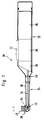
- reference numeral 20 denotes an electric toothbrush.
- the toothbrush 20 consists of a handle part 22 and a brush part 24 that can be coupled to the handle part 22.
- the handle part 22 takes on an accumulator 26 or also a battery, an electric motor 28 and a reversing device 30 for converting the continuous rotational movement of the electric motor 28 into an alternating rotary movement .
- a switch 32 for activating the toothbrush 20 is arranged on the outside of the handle.
- the brush part 24 consists of a hollow support tube 36 which receives a shaft 34.
- the carrier tube 36 and the shaft 34 can be connected to the handle part 22 by means 40, not shown in FIG. 1.
- the bristle part 24 has a bristle carrier 38 with a carrier plate 49 for receiving bristles 45 or tufts of bristles.
- the bristle carrier 38 is driven via a bevel gear 42 arranged at the head end of the shaft 34.
- the axis of rotation of the bristle carrier 38 includes an angle of approximately 90 ° with the axis of rotation of the shaft 34. However, without restricting the invention, this angle can also assume values of 30 ° to 120 °.
- Via the bevel gear 42 the torque of the alternately rotatable shaft 34 is transmitted to the bristle carrier 38 arranged at an angle to the shaft 34.
- the range of rotation angles swept by the bristle carrier 38 can assume values in the range between +/- 20 ° and +/- 100 °, but preferably a value of approximately +/- 35 °.
- FIG. 2 shows the section of the toothbrush 20 that is essential for the representation of the connecting means 40 in a longitudinal section.
- the handle part 22 accommodates an inner housing part 18 in which, among other things, the drive means of the toothbrush are arranged.
- a lip seal 21 arranged between the housing inner part 18 and the handle part 22 surrounds the drive shaft 23, which is cylindrical in this area, and prevents dirt and moisture from penetrating into the interior of the handle part 22.
- a central bore 29 of a housing shaft 66 integrally formed on the handle part 22 leads to this Drive shaft 23 out of the grip part 22.
- the drive shaft 23 tapers from a circular cross section 83 to an approximately semicircular cross section 84.
- a flat surface 89 delimiting the semicircular end piece 77 of the drive shaft 23 serves to transmit the drive torque of the drive shaft 23 to the shaft 34
- the end piece 77 of the drive shaft 23 has a chamfer 56 following the surface 89.
- a locking notch 54 is provided on the drive shaft 23.
- the brush part 24 consists of a slightly conical carrier tube 36, which receives the shaft 34 inside.
- the shaft 34 is positively connected in the part facing away from the grip part 22 to a shaft piece 75 which serves to drive a bristle carrier (not shown).
- the shaft piece 75 is secured against axial displacement in the direction of a longitudinal central axis of the shaft 34 or the drive shaft 23 by means of a shoulder 51 provided in the support tube 36 and a ring 60 which is held in the interior of the support tube 36 by a retaining ring 62.
- the shaft 34 is in turn secured on the one hand by the shaft piece 75 and, on the other hand, by a profile ring 27 clipped into the support tube 36 on the handle part 22 against axial displacements.
- the shaft 34 is only fixed in the area of the at least positive connection with the shaft piece 75. In the area facing the profile ring 27, the shaft 34 is not secured against radial deflections. This measure enables the shaft 34 to compensate for certain tolerances by changing its angular position with respect to the longitudinal center axis of the drive shaft 23, for example the positional deviation of a drive shaft 23 which is not aligned with the ideal longitudinal center axis.
- the axial securing of the shaft 34 is ensured in detail in that an annular shoulder 58 formed on the shaft 34 is supported on an inner profile 90 (FIG. 4) of the profile ring 27.
- the shaft 34 has a receiving sleeve 82, the inner cross section of which tapers complementarily to the change in cross section of the shaft 23 from a circular cross section 83 to a semicircular cross section 84.
- means 65 are provided in the interior of the receiving sleeve 82, which forcibly align the shaft 34 from any drive position during the coupling process between the drive shaft 23 and the shaft 34 into a predetermined coupling position. Two preferred embodiments these means are shown in more detail in FIGS. 5 and 6.
- the inner cross section of the receiving sleeve 82 widens conically in the direction of the annular shoulder 58, as a result of which insertion of the drive shaft 23 into the receiving sleeve 82 is facilitated.
- the profile ring 27 is provided over its outer circumference with an annular thickening 68 which, in conjunction with an annular groove 69 arranged on the inner wall of the support tube 36, serves as a fastening or latching means for fixing the profile ring 27 in the support tube 36.
- the profile ring 27 has a plurality of axial longitudinal webs 70 arranged on the outer wall, which engage in axial longitudinal grooves 71 located on the inner wall of the carrier tube 36. Through these measures, the profile ring 27 is secured against rotation within the support tube 36. From the carrier tube 36 protruding locking means 96 of the profile ring 27 are used to attach a color ring 25, so that the brush portion 24 can be individually identified.
- the inner profile 90 of the profile ring 27 and an outer profile 91 of the housing shaft 66 act together as a radial lock 41 for the rotationally fixed connection of the support tube 36 to the handle part 22.
- the axial securing of the brush part 24 on the handle part 22, that is, a securing of the brush part 24 against slipping of the brush part 24 from the grip part 22 in the direction of the longitudinal center axis of the drive shaft 23 is accomplished in that a spring tongue 50 is provided on the shaft 34 in the region of the receiving sleeve 82, which tongue has a latching nose 52 at its resilient end.
- the mode of operation of the radial lock 41 is explained in more detail below with the aid of the illustration in FIGS. 3 and 4.
- the view AA of the housing shaft 66 of FIG. 3 shows the special, advantageous profiling of the side wall region of the housing shaft 66.
- the housing shaft 66 has the basic shape of a straight cylinder or a straight truncated cone, the housing shaft 66 in the latter case moving in the direction of the head end of the Handle part 22 tapers to facilitate insertion into the complementarily shaped profile ring 27.
- the guide curve of the cylinder or cone surface has a 180 ° rotational symmetry and is formed in two diametrically opposite areas by a 90 ° arc 98.
- arcs 98 of the leading curve are connected by alternately concave sections 73 and convex sections 72. Between the concave sections 73 and convex sections 72, the guide curve is formed by straight lines 85, 86, 87. In this case, lines 86 and 87 which are adjacent to one another and lines 86, 85 opposite one another in mirror image form an angle of approximately 90 ° with one another.
- this angle of the straight lines 85, 86 and 87 to one another or the associated cylinder or truncated cone wall surfaces leads in particular to an optimal introduction of force into the rare wall surfaces of the housing shaft 66 when the drive shaft 23 rotates left and right or alternates the direction of rotation is changing, driven.
- the arcs 98 are connected on both sides via two concave sections 73 and three convex sections 72.
- a chamfer 97 in the area of the cylinder wall surfaces formed by the circular arcs 98 makes it easier to insert the housing shaft 66 into the profile ring 27.
- the inner profile 90 of the profile ring 27 is complementary to the outer profile 91 of the housing shaft 66, as can be seen in particular from the section B-B in FIG. 4.
- the profile ring 27 has a circular inner cross section 88 (section DD of FIG. 4), which tapers in the shape of a cone and merges into the inner profile 90 of the profile ring 27. This measure makes it possible to insert the housing shaft 66 into the profile ring 27 considerably relieved.
- the particular embodiment of the exemplary embodiment with regard to the arrangement of the mutually adjacent or opposite straight lines 85, 86 and 87 and the associated cylinder or truncated cone surfaces in an approximately rectangular assignment to one another is particularly advantageous when an alternating rotary movement of the drive shaft 23 on the shaft 34 is to be transferred.
- the special inner or outer profile 90, 91 also has an advantageous effect on the transmission of a continuous rotary movement, be it left-handed or right-handed, from the drive shaft 23 to the shaft 34.
- the shaft 34 is shown in detail in FIG. 5.
- the outer wall of the shaft 34 is pierced in the area of the receiving sleeve 82 by a U-shaped recess 95, as a result of which a spring tongue 50 is formed.
- the locking lug 52 formed on the inner wall of the spring tongue 50 engages in the locking notch 54 of the drive shaft 23 and, via this locking, fixes the brush part 24 on the handle part 22 in the axial direction.
- a power transmission between the drive shaft 22 and the shaft 34 is ensured via the semicircular cross-sections 84 of the drive shaft 23 and the receiving opening of the receiving sleeve 82, the flat surfaces 89 of the drive shaft 23 and a surface 93 of the receiving sleeve 82 being opposite one another.
- the positive guidance means consist of a wedge-shaped nose 67 which is arranged in the inner wall region of the receiving sleeve 82 and is diametrically opposite the spring tongue 50. Screw surfaces 76, 78 are provided on both sides of the nose 67, the screw surface 76 having a left slope and the screw surface 78 having a right slope.
- the two screw surfaces 76, 78 are constructively generated by a straight line which perpendicularly intersects the longitudinal central axis of the shaft 34.
- the screw surfaces 76, 78 run out into the flat surface 93.
- This measure allows relative rotations of the drive shaft 23 with respect to the shaft 34 of approximately +/- 90 ° to be compensated.
- a larger range than +/- 90 ° is not necessary in the present exemplary embodiment because the rotational movement of the shaft 34 and drive shaft 23 is restricted to a range of maximum +/- 70 ° by one zero position by means not shown.
- An expansion of the "catch area" of the means 65 for the positive guidance of the shaft 34 to a range of approximately +/- 180 ° is, however, easily possible, for example, by the fact that the positive connections between the drive shaft 23 and the receiving sleeve 82 in a 180 ° rotational symmetry be configured with respect to the longitudinal central axis of the shaft 34.
- the "correct" position of the brush part 24 and the grip part 22 is first determined by the fact that the housing shaft 66 must be insertable into the profile ring 27. Relative rotations of the drive shaft 23 and shaft 34 with respect to this “correct” position are then compensated for by the means 65 for positive alignment during the coupling process.
- FIG. 6 A further embodiment of the means 65 for the forced guidance of the shaft 34 is shown in FIG. 6, the other embodiment of the shaft 34 being unchanged.
- the position of the cuts GG and CC of FIG. 6 corresponds to that of FIG. 5.
- the means 65 for positive guidance are designed as a circular segment profile 80, which is arranged in the receiving sleeve 82 instead of the wedge-shaped nose 67 opposite the spring tongue 50.
- the chamfer 56 of the drive shaft 23 interacts with this circular segment profile 80.
- the inclined surface of the chamfer 56 exerts a force on the insertion of the drive shaft 23 into the receiving sleeve 82 Circular segment profile 80 a torque on the shaft 34, such that the shaft 34 automatically into the correct coupling position is aligned.
- the embodiment of the means 65 according to the example of FIG. 6 has the advantage over the embodiment according to FIG. 5 that the injection mold for creating the shaft 34 can be constructed more simply. In terms of effect, the means 65 of FIGS. 5 and 6 are essentially identical.
- the invention is preferably, but not exclusively, applied to a toothbrush whose bristle carrier 38 rotates alternately at an angle of approximately +/- 35 ° perpendicular to the longitudinal central axis of the brush part 24, and which is described in the international application PCT / DE90 / 00672, WO91 / 07116.
- the shaft 34 does not have to be fixed in the area of the annular shoulder 58 with respect to a radial deflection and therefore the longitudinal center axis of the drive shaft 23 does not have to be exactly aligned with the longitudinal center axis of the shaft 34.
- the locking means which are subject to wear - here in particular the locking lug 52 and the spring tongue 50 to parts of the toothbrush, namely the brush part 24, which is subject to frequent replacement anyway for medical or hygienic reasons.
- the handle part 22 as a durable, non-exchangeable part has no locking means and is therefore not subject to wear due to frequent connection of the brush part 24 to the handle part 22.
Landscapes
- Health & Medical Sciences (AREA)
- Dentistry (AREA)
- Epidemiology (AREA)
- Life Sciences & Earth Sciences (AREA)
- Animal Behavior & Ethology (AREA)
- General Health & Medical Sciences (AREA)
- Public Health (AREA)
- Veterinary Medicine (AREA)
- Brushes (AREA)
Description
- Die Erfindung geht aus von einer elektrischen Zahnbürste, bestehend aus einem Griffteil mit einem elektromotorischen Antrieb sowie einer Antriebswelle und einem Bürstenteil mit einer Welle zum Antrieb eines drehbaren Borstenträgers und einem Gehäuse zur Aufnahme der Welle sowie zur Lagerung des Borstenträgers. Dabei ist der Bürstenteil mit dem Griffteil über Kupplungsmittel zur Festlegung des Bürstenteils am Griffteil verbindbar und die Antriebswelle mit der Welle über Kopplungsmittel koppelbar, wobei Kupplungsmittel, die dem Gehäuse des Bürstenteils und dem Griffteil zugeordnet sind, zusammenwirken.
- Bereits aus der US-PS 4 827 552 ist eine elektrische Zahnbürste mit diesen Merkmalen bekannt. Der lösbare Bürstenteil dieser Zahnbürste muß einerseits axial gesichert werden, um ein unbeabsichtigtes Lösen des Bürstenteils vom Griffteil, beispielsweise während des Gebrauchs der Zahnbürste, zu vermeiden. Dadurch, daß der Borstenträger bzw. die Bürste durch den elektromotorischen Antrieb in eine Rotationsbewegung versetzt wird, muß das Gehäuse des Bürstenteils aber auch gegen eine radiale Verdrehung bezüglich des Griffteils gesichert werden, um ein Mitdrehen des Gehäuses mit der vom Gehäuse aufgenommenen Welle zu verhindern. Diese radiale und axiale Sicherung wird bei der bekannten Zahnbürste dadurch realisiert, daß am Griffteil angeordnete, knopfartige Erhöhungen in entsprechende am Gehäuse des Bürstenteils angeordnete Vertiefungen einrasten. Die Festlegung des Bürstenteils am Griffteil in axialer und radialer Richtung erfolgt somit durch ein einziges Kupplungsmittel. Nachteilig erweist sich diese Anordnung dadurch, daß Toleranzen in der Positionierung der zu kuppelnden Teile, nämlich des Griffteils und des Gehäuseteils sowie der Antriebswelle und der Welle im Gehäuseteil nicht ohne weiteres ausgeglichen werden können. Sofern die Antriebswelle und die Welle des Bürstenteils nicht exakt miteinander fluchten, ist eine Kupplung des Bürstenteils mit dem Griffteil unter Vermeidung von Verspannungen zwischen dem Gehäuseteil und dem Griffteil praktisch nicht möglich. Darüber hinaus werden im allgemeinen die Gehäuseteile elektrischer Zahnbürsten als Spritzgußteile aus technischem Kunststoff hergestellt. Die Kupplungsmittel sind daher aufgrund der Verwendung relativ weicher Materialien, einem gewissen Verschleiß unterworfen und verlieren im Laufe der Gebrauchsdauer der Zahnbürste ihre Funktionsfähigkeit.
- Es ist Aufgabe der Erfindung, eine elektrische Zahnbürste mit den eingangs erwähnten Merkmalen derart weiterzubilden, daß eine sichere Kupplung von Bürstenteil und Griffteil auch unter Inkaufnahme gewisser Toleranzen in der Positionierung der kuppelnden Teile zueinander gewährleistet Ist. Des weiteren soll die Anordnung der Kupplungsmittel derart getroffen werden, daß ein möglicher Verschleiß der Kupplungsmittel nicht zu einer Beeinträchtigung der Funktionsfähigkeit der Zahnbürste führt.
- Diese Aufgabe wird durch eine elektrische Zahnbürste der eingangs genannten Art dadurch gelöst, daß eine Festlegung des Bürstenteils am Griffteil in, bezogen auf eine Längsmittelachse der Welle, axialer und radialer Richtung, jeweils durch separate Kupplungsmittel bewirkt wird, wobei Kupplungsmittel, die der Antriebswelle und der Welle zugeordnet sind, zusammenwirken.
- Im Sprachgebrauch der vorliegenden Anmeldung wird unter den Begriffen Kupplungsmittel und Kopplungsmittel folgendes verstanden: Ist von "Kupplungsmitteln" die Rede, ist eine Verbindung der Gehäuseteile des Bürstenteils und des Griffteils gemeint. Hingegen wird durch "Kopplungsmittel" eine Verbindung der Antriebswelle mit der Welle im Bürstenteil zur Drehmomentübertragung beschrieben.
- Die funktionelle Auftrennung der Kupplungsmittel in solche Mittel, die lediglich zur radialen Festlegung und in andere Kupplungsmittel, die lediglich zur axialen Festlegung des Bürstenteils am Griffteil dienen, schafft die Voraussetzung dafür, daß Lagetoleranzen der Kupplungsteile zueinander ausgeglichen werden können. Die zu kuppelnden Teile, die die Mittel zur axialen Festlegung aufweisen, können hinsichtlich der radialen Positionierung zueinander Lagetoleranzen aufweisen. Andererseits können die Teile, die mit den Kupplungsmitteln zur radialen Festlegung des Bürstenteils am Griffteil ausgestattet sind, axiale Lagetoleranzen zueinander aufweisen. Durch diese Maßnahmen kann unter Inkaufnahme von gewissen Toleranzen in der Positionierung der zu kuppelnden Teile untereinander, so zum Beispiel für den Fall einer mit der Welle im Bürstenteil nicht fluchtenden Antriebswelle, oder für den Fall gewisser Toleranzen der Länge der Welle bzw. Antriebswelle oder des Gehäuses des Bürstenteils, dennoch eine sichere und spannungsfreie Verbindung des Bürstenteils mit dem Griffteil erfolgen. Darüber hinaus erlaubt die funktionelle Auftrennung in Mittel zur axialen und radialen Festlegung eine Anordnung der einem Verschleiß unterworfenen Mittel in solche Teile der Zahnbürste, die aus hygienischen bzw. zahnmedizinischen Gründen ohnehin von Zeit zu Zeit auszutauschen sind. Durch die Maßnahme, daß die Kopplungsmittel der Antriebswelle und Welle als Axialsicherung und die Kupplungsmittel des Gehäuses des Bürstenteils und des Griffteils als Radialsicherung zur Festlegung des Bürstenteils am Griffteil ausgebildet sind, wird die an und für sich geringen Verschleiß unterworfene Radialsicherung in den Bereich des Griffteils der Zahnbürste gelegt, während die höherem Verschleiß unterworfene Axialsicherung in den Bereich der Welle bzw. Antriebswelle verlagert wird. Die Antriebswelle besteht bei elektrischen Zahnbürsten in aller Regel aus einem verschleißfreien Material, z.B. Edelstahl, während die Welle zum Antrieb eines Borstenträgers aus verschleißanfälligerem Material, wie zum Beispiel einem technischen Kunststoff, hergestellt ist. Die verschleißanfälligen Teile der Mittel sind im Bereich des Bürstenteils angeordnet, welcher aufgrund von Abnutzungserscheinungen der Borsten des im Bürstenteil gelagerten Borstenträgers bzw. aus hygienischen Gründen nach einem gewissen Zeitraum, im Bereich zwischen etwa 2-4 Monaten, ausgetauscht werden sollte. Der Griffteil der Zahnbürste mit den hochwertigen Komponenten, wie Akkumulatoren, Elektromotor und Getriebe ist jedenfalls infolge der Verbindung des Bürstenteils mit dem Griffteil durch die spezielle Anordnung der Mittel keinem Verschleiß unterworfen. Dadurch, daß die Axialsicherung mittels Rastmittel der Welle erfolgt, die in ein Widerlager der Antriebswelle eingreifen, wird eine robuste Ausführung der axialen Sicherung angegeben, bei der das in hohem Maße dem Verschleiß unterworfene Rastmittel an der Welle ohnehin durch Austausch des Bürstenteils von Zeit zu Zeit erneuert wird. Die Maßnahme, in eine Aufnahmehülse der Welle zur Aufnahme der Antriebswelle Mittel vorzusehen, die die Welle aus einer beliebigen Antriebsstellung heraus beim Kopplungsvorgang zwischen der Antriebswelle und der Welle zwangsweise in eine vorgegebene Kopplungsposition ausrichten, dient einer sicheren, unproblematischen axialen Festlegung der Teile. Die Tatsache, daß zwischen der Antriebwelle und der Welle Drehmomente zu übertragen und infolgedessen im Kopplungsbereich beider Wellen Kraftübertragungsflächen anzubringen sind, schließt es aus, daß beide Wellen in jeder beliebigen Position zueinander miteinander verbindbar sind. Die Mittel zur Zwangsausrichtung der Welle bezüglich der Antriebswelle, die während des Kopplungsvorganges beider Wellen wirksam werden, erleichtern das Koppeln beider Wellen in besonders vorteilhafter Weise. Diese Mittel zur Zwangsausrichtung können einerseits durch in einer Aufnahmehülse der Welle angeordnete rechts- und linkssteigende Schraubenflächen, die mit einem einseitig abgeflachten Endstück der Antriebswelle zusammenwirken oder andererseits durch ein Kreissegmentprofil, das mit einer Fase am Endstück der Antriebswelle zusammenwirkt, realisiert werden. Beide Maßnahmen bewirken beim Einführen der Antriebswelle in die Aufnahmehülse der Welle eine sichere, zwangsweise Ausrichtung der Welle bezüglich der Antriebswelle, wobei die letztgenannte Maßnahme sich durch eine besonders einfache Herstellbarkeit der Spritzgußform für die Welle auszeichnet. Die Maßnahme, daß eine Radialsicherung mittels kraftübertragender Außenwandflächen des Griffteils erfolgt, welche mit entsprechenden, komplementär geformten Innenwandflächen des Gehäuses des Bürstenteils zusammenwirken, hat den Vorteil, daß jegliche Krafteinleitung im Bereich der Radialsicherung flächig erfolgt und Kantenberührungen bzw. Punktberührungen, welche zum Verschleiß oder zur Verletzung des Gehäuses im Bereich der Radialsicherung führen könnten, vermieden werden. Insbesondere bei der Verwendung von technischen Kunststoffen für die Ausbildung der Teile für die Radialsicherung machen sich die relativ großen Kraftangriffsflächen zur Vermeidung von Verletzungen oder Verschleiß der Gehäuseteile äußerst vorteilhaft bemerkbar. Dadurch, daß einander benachbarte, kraftübertragende Flächen in einem Winkel von etwa 90° angeordnet sind, ergibt sich eine optimale Krafteinleitung im Bereich der Radialsicherung, unabhängig davon, ob die Antriebswelle im oder gegen den Uhrzeigersinn rotiert. Insbesondere für einen alternierend rotierenden Antrieb der Welle ergeben sich aus der Anordnung von einander gegenüberliegenden, kraftübertragenden Flächen in einem Winkel von etwa 90° vorteilhafte Verhältnisse für die Krafteinleitung. Schließlich ermöglicht die Ausgestaltung der Übergänge zwischen den einzelnen, benachbarten, kraftübertragenden Flächen als konkave bzw. konvexe Teilflächen eines Zylinders oder Kegels eine einfache und problemlose Zusammenfügung des Griffteils und Gehäuseteils im Bereich der Radialsicherung.
- Weitere Vorteile der Erfindung ergeben sich aus der nachfolgenden Beschreibung der Ausführungsbeispiele in Verbindung mit den Figuren.
- Es zeigen:
- Fig. 1
- einen schematischen Schnitt einer elektrischen Zahnbürste mit Mitteln zur Verbindung von Bürstenteil und Griffteil,
- Fig. 2
- einen Längsschnitt durch die Zahnbürste der Fig. 1 im Bereich der Mittel,
- Fig. 3
- eine Ansicht A-A des Gehäuseschafts der Fig. 2,
- Fig. 4 a - d
- verschiedene Schnitte und eine Ansicht eines Profilringes,
- Fig. 5 a,b,c,e,g
- eine Ansicht und verschiedene Schnitte der Welle 34 mit einem ersten Ausführungsbeispiel der Mittel zur Zwangsführung und
- Fig. 6 c,g
- ein zweites Ausführungsbeispiel der Mittel zur Zwangsführung in zwei Schnitten.
- In Figur 1 ist mit der Bezugsziffer 20 eine elektrische Zahnbürste bezeichnet. Die Zahnbürste 20 besteht aus einem Griffteil 22 und einem an dem Griffteil 22 ankuppelbaren Bürstenteil 24. Der Griffteil 22 nimmt auf einen Akkumulator 26 oder auch eine Batterie, einen Elektromotor 28 und eine Umsteuerungseinrichtung 30 zur Umsetzung der kontinuierlichen Rotationsbewegung des Elektromotors 28 in eine alternierende Drehbewegung. Am Griffteil außen ist ein Schalter 32 zur Aktivierung der Zahnbürste 20 angeordnet. Der Bürstenteil 24 besteht aus einem hohlen Trägerrohr 36, welches eine Welle 34 aufnimmt. Das Trägerrohr 36 und die Welle 34 sind über in Fig. 1 nicht näher dargestellte Mittel 40 mit dem Griffteil 22 verbindbar. An dem dem Griffteil 22 abgewandten Ende des Bürstenteils 24 ist ein Borstenträger 38 angeordnet mit einer Trägerplatte 49 zur Aufnahme von Borsten 45 bzw. Borstenbüscheln. Der Borstenträger 38 wird über ein am Kopfende der Welle 34 angeordnetes Kegelradgetriebe 42 angetrieben. Die Drehachse des Borstenträgers 38 schließt mit der Drehachse der Welle 34 einen Winkel von ca. 90° ein. Dieser Winkel kann jedoch, ohne die Erfindung zu beschränken, auch Werte von 30° - 120° einnehmen. Über das Kegelradgetriebe 42 wird das Drehmoment der alternierend drehbaren Welle 34 auf den im Winkel zur Welle 34 angeordneten Borstenträger 38 übertragen. Der vom Borstenträger 38 überstrichene Drehwinkelbereich kann Werte im Bereich zwischen +/- 20° und +/- 100° annehmen, bevorzugt jedoch einen Wert von etwa +/-35°.
- In Fig. 2 ist der für die Darstellung der Verbindungsmittel 40 wesentliche Abschnitt der Zahnbürste 20 im Längsschnitt dargestellt. Der Griffteil 22 nimmt einen Gehäuseinnenteil 18 auf, in dem unter anderem die Antriebsmittel der Zahnbürste angeordnet sind. Eine zwischen dem Gehäuseinnenteil 18 und dem Griffteil 22 angeordnete Lippendichtung 21 umschließt die in diesem Bereich zylindrische Antriebswelle 23 und verhindert ein Eindringen von Schmutz und Feuchtigkeit in das Innere des Griffteils 22. Durch eine zentrale Bohrung 29 eines am Griffteil 22 einstückig angeformten Gehäuseschafts 66 tritt die Antriebswelle 23 aus dem Griffteil 22 heraus. In einem Übergangsbereich 64 der Antriebswelle 23 verjüngt sich die Antriebswelle 23 von einem kreisförmigen Querschnitt 83 auf einen in etwa halbkreisförmigen Querschnitt 84. Eine ebene, das halbkreisförmige Endstück 77 der Antriebswelle 23 begrenzende Fläche 89 dient zur Übertragung des Antriebsmoments der Antriebswelle 23 auf die Welle 34. Das Endstück 77 der Antriebswelle 23 weist eine Fase 56 im Anschluß an die Fläche 89 auf. Im der Fläche 89 abgewandten Bereich des Endstücks 77 ist eine Rastkerbe 54 an der Antriebswelle 23 vorgesehen.
- Der Bürstenteil 24 besteht aus einem leicht konisch auslaufenden Trägerrohr 36, welches im Inneren die Welle 34 aufnimmt. Die Welle 34 ist im dem Griffteil 22 abgewandten Teil formschlüssig mit einem Wellenstück 75 verbunden, welches zum Antrieb eines nicht dargestellten Borstenträgers dient. Das Wellenstück 75 ist mittels einer Im Trägerrohr 36 vorgesehenen Schulter 51 und eines Ringes 60, der durch einen Sicherungsring 62 im Inneren des Trägerrohrs 36 gehalten ist, gegen eine axiale Verschiebung in Richtung einer Längsmittelachse der Welle 34 bzw. der Antriebswelle 23 gesichert. Die Welle 34 ihrerseits ist zum einen durch das Wellenstück 75 und zum anderen durch einen im Trägerrohr 36 am dem Griffteil 22 zugewandten Ende, eingeklipsten Profilring 27 gegen axiale Verschiebungen gesichert. Radial ist die Welle 34 lediglich im Bereich der wenigstens formschlüssigen Verbindung mit dem Wellenstück 75 festgelegt. In dem dem Profilring 27 zugewandten Bereich ist die Welle 34 gegen radiale Auslenkungen nicht gesichert. Durch diese Maßnahme kann die Welle 34 durch eine Veränderung ihrer Winkellage bezüglich der Längsmittelachse der Antriebswelle 23 gewisse Toleranzen, so zum Beispiel die Lageabweichung einer mit der idealen Längsmittelachse nicht fluchtenden Antriebswelle 23 ausgleichen. Die axiale Sicherung der Welle 34 wird im einzelnen dadurch gewährleistet, daß sich eine an der Welle 34 angeformte Ringschulter 58 an einem Innenprofil 90 (Fig. 4) des Profilringes 27 abstützt. Zur Aufnahme der Antriebswelle 23 weist die Welle 34 eine Aufnahmehülse 82 auf, deren Innenquerschnitt sich komplementär der Querschnittsänderung der Welle 23 von einem kreisförmigen Querschnitt 83 auf einen halbkreisförmigen Querschnitt 84 verjüngt. Im Übergangsbereich zwischen diesen beiden Querschnittsformen sind im Inneren der Aufnahmehülse 82 Mittel 65 vorgesehen, die die Welle 34 aus einer beliebigen Antriebstellung heraus beim Kopplungsvorgang zwischen der Antriebswelle 23 und der Welle 34 zwangsweise in eine vorgegebene Kopplungsposition ausrichten. Zwei bevorzugte Ausführungsformen dieser Mittel sind in den Figuren 5 und 6 detaillierter wiedergegeben. In Richtung der Ringschulter 58 erweitert sich der Innenquerschnitt der Aufnahmehülse 82 kegelförmig, wodurch ein Einführen der Antriebswelle 23 in die Aufnahmehülse 82 erleichtert wird. Der Profilring 27 Ist über seinen Außenumfang mit einer ringförmigen Verdickung 68 versehen, welche in Verbindung mit einer an der Innenwand des Trägerrohrs 36 angeordneten Ringnut 69 als Befestigungs- bzw. Rastmittel zur Fixierung des Profilringes 27 Im Trägerrohr 36 dient. Der Profilring 27 weist mehrere an der Außenwand angeordnete, axiale Längsstege 70 auf, welche in an der Innenwand des Trägerrohrs 36 befindliche axiale Längsnuten 71 eingreifen. Durch diese Maßnahmen ist der Profilring 27 gegen ein Verdrehen innerhalb des Trägerrohrs 36 gesichert. Aus dem Trägerrohr 36 herausragende Rastmittel 96 des Profilrings 27 dienen zur Befestigung eines Farbringes 25, so daß der Bürstenteil 24 individuell kennzeichenbar ist.
- Das Innenprofil 90 des Profilringes 27 und ein Außenprofil 91 des Gehäuseschafts 66 wirken zusammen als Radialsicherung 41 zur drehfesten Verbindung des Trägerrohrs 36 mit dem Griffteil 22. Die axiale Sicherung des Bürstenteils 24 am Griffteil 22, also eine Sicherung des Bürstenteils 24 gegen ein Abrutschen des Bürstenteils 24 vom Griffteil 22 in Richtung der Längsmittelachse der Antriebswelle 23 wird dadurch bewerkstelligt, daß an der Welle 34 im Bereich der Aufnahmehülse 82 eine Federzunge 50 vorgesehen ist, welche an ihrem federnden Ende eine Rastnase 52 trägt. Nach Einführen der Antriebswelle 23 in die Aufnahmehülse 82 greift die Rastnase 52 in die Rastkerbe 54 der Antriebswelle 23 ein und sorgt für eine axiale Festlegung des Bürstenteils 24 am Griffteil 22.
- Anhand der Darstellung der Figuren 3 und 4 wird die Wirkungsweise der Radialsicherung 41 im folgenden näher erläutert. Die Ansicht A-A des Gehäuseschafts 66 der Figur 3 zeigt die besondere, vorteilhafte Profilierung des Seitenwandbereiches des Gehäuseschafts 66. Der Gehäuseschaft 66 weist die Grundform eines geraden Zylinders bzw. eines geraden Kegelstumpfs auf, wobei sich der Gehäuseschaft 66 im letztgenannten Fall in Richtung des Kopfendes des Griffteils 22 verjüngt, um ein Einführen in den komplementär geformten Profilring 27 zu erleichtern. Die Leitkurve der Zylinder- bzw. Kegelfläche weist eine 180°-Drehsymmetrie auf, und wird an zwei einander diametral gegenüberliegenden Bereichen durch einen 90°-Kreisbogen 98 gebildet. Diese Kreisbögen 98 der Leitkurve (zur Definition des Begriffs "Leitkurve" siehe beispielsweise Bronstein-Semendjajew, Taschenbuch der Mathematik, Verlag Harri Deutsch, 9. Auflage 1969, Seite 149 - 151) sind über abwechselnd konkave Abschnitte 73 und konvexe Abschnitte 72 verbunden. Zwischen den konkaven Abschnitten 73 und konvexen Abschnitten 72 wird die Leitkurve durch Geraden 85, 86, 87 gebildet. Dabei schließen einander benachbarte Geraden 86 und 87 sowie einander spiegelbildlich gegenüberliegende Geraden 86, 85 miteinander einen Winkel von ca. 90° ein. Es hat sich gezeigt, daß dieser Winkel der Geraden 85, 86 und 87 zueinander bzw. der zugehörigen Zylinder- bzw. Kegelstumpfwandflächen insbesondere dann zu einer optimalen Krafteinleitung in die Seltenwandflächen des Gehäuseschafts 66 führt, wenn die Antriebswelle 23 links- und rechtsdrehend bzw. alternierend die Drehrichtung wechselnd, angetrieben ist. Im speziellen Ausführungsbeispiel der Fig. 3 sind die Kreisbögen 98 auf beiden Seiten über jeweils zwei konkave Abschnitte 73 und drei konvexe Abschnitte 72 verbunden. Eine Fase 97 im Bereich der durch die Kreisbögen 98 gebildeten Zylinderwandflächen sorgt für eine Erleichterung der Einführung des Gehäuseschafts 66 in den Profilring 27.
- Das Innenprofil 90 des Profilringes 27 ist komplementär zum Außenprofil 91 des Gehäuseschafts 66 gestaltet, wie insbesondere aus dem Schnitt B-B der Fig. 4 erkennbar ist. Im Bereich der Rastmittel 96 weist der Profilring 27 einen kreisförmigen Innenquerschnitt 88 (Schnitt D-D der Fig. 4) auf, der sich kegelmantelförmig verjüngt und übergeht in das Innenprofil 90 des Profilringes 27. Durch diese Maßnahme wird das Einführen des Gehäuseschafts 66 in den Profilring 27 erheblich erleichtert.
- Aufgrund der besonderen Gestaltung des Innenprofils 90 des Profilringes 27 und des entsprechenden, komplementären Außenprofils 91 des Gehäuseschafts 66 werden die zwischen dem Gehäuseschaft 66 und dem Profilring 27 zu übertragenden Drehmomente bzw. Kräfte flächig in die jeweiligen Bauteile eingeleitet. Eine Linien- oder Punktberührung der zusammenwirkenden Bauteile, die zu einer Beschädigung oder zu einem erhöhten Verschleiß der Oberflächen der Teile führt, ist praktisch ausgeschlossen. Dieser Vorteil macht sich insbesondere bei den im vorliegenden Ausführungsbeispiel Anwendung findenden Werkstoffen - Griffteil 22 und Profilring 27 bestehen aus technischem Kunststoff - in besonderer Weise vorteilhaft bemerkbar. Die besondere Ausgestaltung des Ausführungsbeispiels hinsichtlich der Anordnung der einander benachbarten bzw. gegenüberliegenden Geraden 85, 86 und 87 und der zugehörigen Zylinder- oder Kegelstumpfflächen in ungefähr rechtwinkliger Zuordnung zueinander, ist insbesondere dann von Vorteil, wenn eine alternierende Drehbewegung der Antriebswelle 23 auf die Welle 34 zu übertragen ist. Aber auch für eine Übertragung einer kontinuierlichen Drehbewegung, sei es nun links- oder rechtsdrehend, von der Antriebswelle 23 auf die Welle 34, kommt das spezielle Innen- bzw. Außenprofil 90, 91 vorteilhaft zum Tragen.
- Die Welle 34 ist in Fig. 5 im einzelnen dargestellt. Die Außenwand der Welle 34 ist im Bereich der Aufnahmehülse 82 von einer U-förmigen Aussparung 95 durchbrochen, wodurch eine Federzunge 50 gebildet wird. Die an der Innenwand der Federzunge 50 angeformte Rastnase 52 greift in die Rastkerbe 54 der Antriebswelle 23 ein und legt über diese Rastung den Bürstenteil 24 am Griffteil 22 in axialer Richtung fest. Eine Kraftübertragung zwischen der Antriebswelle 22 und der Welle 34 ist über die halbkreisförmigen Querschnitte 84 der Antriebswelle 23 und der Aufnahmeöffnung der Aufnahmehülse 82 gewährleistet, wobei die ebenen Flächen 89 der Antriebswelle 23 und eine Fläche 93 der Aufnahmehülse 82 einander gegenüberliegen. Zur Erleichterung des Einführens der Antriebswelle 23 in die Aufnahmehülse 82 sind im Inneren der Aufnahmehülse 82 Mittel zur Zwangsausrichtung der Welle 34 bezüglich der Antriebswelle 23, die beim Einführen wirksam werden, vorgesehen. Die Zwangsführungsmittel bestehen in einem ersten Ausführungsbeispiel (Fig. 5) aus einer im Innenwandbereich der Aufnahmehülse 82 angeordneten, keilförmigen Nase 67, welche der Federzunge 50 diametral gegenüberliegt. Beiderseits der Nase 67 sind Schraubenflächen 76, 78 vorgesehen, wobei die Schraubenfläche 76 eine Linkssteigung und die Schraubenfläche 78 eine Rechtssteigung aufweist. Die beiden Schraubenflächen 76, 78 werden konstruktiv durch eine Gerade erzeugt, die die Längsmittelachse der Welle 34 senkrecht schneidet. Die Schraubenflächen 76, 78 laufen aus in die ebene Fläche 93. Befinden sich die Antriebswelle 23 und die Welle 34 vor Beginn des Kupplungsvorganges des Bürstenteils 24 an dem Griffteil 22 in einer verdrehten Positionierung zueinander, derart, daß der halbkreisförmige Querschnitt 84 der Antriebswelle 23 und der Aufnahmehülse 82 nicht miteinander zur Deckung kommen, so wirken die Fläche 89 der Antriebswelle 23 und die Schraubenfläche 76 oder 78 in der Weise zusammen, daß beim Einführen der Antriebswelle 23 in die Aufnahmehülse 82 die Welle 34, entweder rechts- oder linksherum, in die passende Kopplungsposition selbsttätig gedreht wird. Durch diese Maßnahme können Relativverdrehungen der Antriebswelle 23 bezüglich der Welle 34 von ca. +/- 90° ausgeglichen werden. Ein größerer Bereich als +/- 90° ist im vorliegenden Ausführungsbeispiel deshalb nicht erforderlich, da die Drehbewegung der Welle 34 und Antriebswelle 23 durch nicht dargestellte Mittel auf einen Bereich von maximal +/- 70° um eine Nullage eingeschränkt ist. Eine Ausweitung des "Fangbereiches" der Mittel 65 zur Zwangsführung der Welle 34 auf einen Bereich von ca. +/- 180° ist jedoch beispielsweise dadurch ohne weiteres möglich, daß die Formschlußverbindungen zwischen der Antriebswelle 23 und der Aufnahmehülse 82 in einer 180°-Drehsymmetrie bezüglich der Längsmittelachse der Welle 34 ausgestaltet werden. Die "richtige" Position von Bürstenteil 24 und Griffteil 22 wird zunächst einmal dadurch bestimmt, daß der Gehäuseschaft 66 in den Profilring 27 einführbar sein muß. Relative Verdrehungen der Antriebswelle 23 und Welle 34 bezüglich dieser "richtigen" Position werden dann durch die Mittel 65 zur Zwangsausrichtung während des Kopplungsvorganges ausgeglichen.
- Eine weitere Ausgestaltung der Mittel 65 zur Zwangsführung der Welle 34 ist in Fig. 6 dargestellt, wobei die sonstige Ausgestaltung der Welle 34 unverändert ist. Auch die Lage der Schnitte G-G und C-C der Fig. 6 entspricht der der Fig. 5. Die Mittel 65 zur Zwangsführung sind als Kreissegmentprofil 80 ausgebildet, welches anstelle der keilförmigen Nase 67 gegenüberliegend der Federzunge 50 in der Aufnahmehülse 82 angeordnet ist. Mit diesem Kreissegmentprofil 80 wirkt zusammen die Fase 56 der Antriebswelle 23. Sind die Welle 34 bzw. die Aufnahmehülse 82 und die Antriebswelle 23 nicht passend zueinander ausgerichtet, so übt die schräge Fläche der Fase 56 beim Einführen der Antriebswelle 23 in die Aufnahmehülse 82 über das Kreissegmentprofil 80 ein Drehmoment auf die Welle 34 aus, derart, daß die Welle 34 selbsttätig in die richtige Kopplungsposition ausgerichtet wird. Die Ausführung der Mittel 65 gemäß dem Beispiel der Fig. 6 hat gegenüber der Ausführungsform gemäß Fig. 5 den Vorteil, daß die Spritzgußform zur Erstellung der Welle 34 einfacher aufgebaut sein kann. Von der Wirkung her sind die Mittel 65 der Fig. 5 und 6 im wesentlichen identisch.
- Die Erfindung findet bevorzugt, aber nicht ausschließlich, auf eine Zahnbürste Anwendung, deren Borstenträger 38 senkrecht zur Längsmittelachse des Bürstenteils 24 alternierend in einem Winkel von ca. +/- 35° rotiert, und die in der internationalen Anmeldung PCT/DE90/00672, WO91/07116 beschrieben ist.
- Aufgrund der beschriebenen funktionellen Trennung der Mittel für eine axiale sowie radiale Festlegung des Bürstenteils 24 am Griffteil 22 lassen sich in vorteilhafter Weise Toleranzen in der Positionierung der zu verbindenden Teile miteinander ausgleichen. So muß zum Beispiel die Welle 34 im Bereich der Ringschulter 58 nicht bezüglich einer radialen Auslenkung festgelegt sein und daher die Längsmittelachse der Antriebswelle 23 nicht exakt mit der Längsmittelachse der Welle 34 fluchten. Darüber hinaus besteht die Möglichkeit, die einem Verschleiß unterworfenen Rastmittel - hier insbesondere die Rastnase 52 und die Federzunge 50 in solche Teile der Zahnbürste, nämlich den Bürstenteil 24 zu verlagern, der aus medizinischen bzw. hygienischen Gründen ohnehin einem häufigeren Austausch unterworfen wird. Der Griffteil 22 als langlebiges, nicht austauschbares Teil weist keinerlei Rastmittel auf und ist daher auch keinem Verschleiß aufgrund häufiger Verbindung des Bürstenteils 24 mit dem Griffteil 22 unterworfen.
Claims (10)
- Elektrische Zahnbürste (20) mit den Merkmalena) ein Griffteil (22) umfaßt einen elektromotorischen Antrieb (28) und eine Antriebswelle (23),b) ein Bürstenteil (24) umfaßt eine Welle (34) zum Antrieb eines drehbaren Borstenträgers (38) und ein Gehäuse zur Aufnahme der Welle (34) sowie zur Lagerung des Borstenträgers (38),c) die Antriebswelle (23) und die Welle (34) sind über Kopplungsmittel (82, 84, 89, 93) miteinander koppelbar,d) der Bürstenteil (24) ist mit dem Griffteil (22) über Kupplungsmittel zur Festlegung des Bürstenteils (24) am Griffteil (22) verbindbar, wobei Kupplungsmittel, die dem Gehäuse des Bürstenteils (24) und dem Griffteil (22) zugeordnet sind, zusammenwirkengekennzeichnet durche) eine Festlegung des Bürstenteils (24) am Griffteil (22) in - bezogen auf eine Längsmittelachse der Welle (34) - axialer und radialer Richtung, jeweils durch separate Kupplungsmittel, wobei Kupplungsmittel (52, 54), die der Antriebswelle (23) und der Welle (34) zugeordnet sind, zusammenwirken.
- Elektrische Zahnbürste nach Anspruch 1, dadurch gekennzeichnet, daß die Kopplungsmittel der Antriebswelle (23) und der Welle (34) als Axialsicherung (44) und die Kupplungsmittel des Gehäuses des Bürstenteils (24) und des Griffteils (22) als Radialsicherung (41) zur Festlegung des Bürstenteils (24) am Griffteil (22) ausgebildet sind.
- Elektrische Zahnbürste nach Anspruch 1 oder 2, dadurch gekennzeichnet, daß eine Axialsicherung (44) mittels Rastmittel (50, 52) der Welle (34) erfolgt, die in ein Widerlager (54) der Antriebswelle (23) eingreifen.
- Elektrische Zahnbürste nach Anspruch 3, dadurch gekennzeichnet, daß eine Aufnahmehülse (82) der Welle (34) zur Aufnahme der Antriebswelle (23) Mittel (65) aufweist, die die Welle (34) aus einer beliebigen Antriebsstellung heraus beim Kopplungsvorgang zwischen der Antriebswelle (23) und der Welle (34) zwangsweise in eine vorgegebene Kopplungsposition ausrichten.
- Elektrische Zahnbürste nach Anspruch 4, dadurch gekennzeichnet, daß die Mittel (65) als rechts- bzw. linkssteigende Schraubenflächen (76, 78) ausgebildet sind, die mit einem einseitig abgeflachten Endstück (77, 89) der Antriebswelle (23) zur Zwangsausrichtung der Welle (34) zusammenwirken.
- Elektrische Zahnbürste nach Anspruch 4, dadurch gekennzeichnet, daß die Mittel (65) als Kreissegmentprofil (80) ausgebildet sind, die mit einer Fase (56) am Endstück (77) der Antriebswelle (23) zur Zwangsausrichtung der Welle (34) zusammenwirken.
- Elektrische Zahnbürste nach wenigstens einem der Ansprüche 1 bis 6, dadurch gekennzeichnet, daß eine Radialsicherung (41) mittels kraftübertragender Wandflächen eines Profils (91) des Griffteils (22) erfolgt, welche mit entsprechenden, komplementär geformten Wandflächen eines Profils (90) des Gehäuses des Bürstenteils (24) zusammenwirken.
- Elektrische Zahnbürste nach Anspruch 7, dadurch gekennzeichnet, daß einander benachbarte, ebene Wandflächenabschnitte der Profile (90, 91) in einem Winkel von etwa 90° zueinander angeordnet sind.
- Elektrische Zahnbürste nach Anspruch 7 oder 8, dadurch gekennzeichnet, daß einander spiegelbildlich gegenüberliegende, ebene Wandflächen der Profile (90, 91) in einem Winkel von etwa 90° zueinander angeordnet sind.
- Elektrische Zahnbürste nach einem der Ansprüche 7 bis 9, dadurch gekennzeichnet, daß die Übergänge zwischen einzelnen benachbarten, ebenen Wandflächen der Profile (90, 91) durch konvexe Abschnitte (72) bzw. konkave Abschnitte (73) eines Zylinders oder Kegelstumpfes gebildet sind.
Applications Claiming Priority (3)
| Application Number | Priority Date | Filing Date | Title |
|---|---|---|---|
| DE3937853 | 1989-11-14 | ||
| DE3937853A DE3937853A1 (de) | 1989-11-14 | 1989-11-14 | Elektrische zahnbuerste mit loesbarem buerstenteil |
| PCT/DE1990/000673 WO1991007117A1 (de) | 1989-11-14 | 1990-09-05 | Elektrische zahnbürste mit lösbarem bürstenteil |
Publications (2)
| Publication Number | Publication Date |
|---|---|
| EP0500537A1 EP0500537A1 (de) | 1992-09-02 |
| EP0500537B1 true EP0500537B1 (de) | 1994-11-30 |
Family
ID=6393500
Family Applications (1)
| Application Number | Title | Priority Date | Filing Date |
|---|---|---|---|
| EP90912750A Expired - Lifetime EP0500537B1 (de) | 1989-11-14 | 1990-09-05 | Elektrische zahnbürste mit lösbarem bürstenteil |
Country Status (8)
| Country | Link |
|---|---|
| US (1) | US5289604A (de) |
| EP (1) | EP0500537B1 (de) |
| JP (1) | JPH0649010B2 (de) |
| AT (1) | ATE114423T1 (de) |
| CA (1) | CA2071880C (de) |
| DE (2) | DE3937853A1 (de) |
| DK (1) | DK0500537T3 (de) |
| WO (1) | WO1991007117A1 (de) |
Cited By (11)
| Publication number | Priority date | Publication date | Assignee | Title |
|---|---|---|---|---|
| US6836917B2 (en) | 2001-05-07 | 2005-01-04 | The Procter & Gamble Company | Replaceable head electric toothbrush and connection structure therefor |
| DE102006060133A1 (de) * | 2006-12-18 | 2008-06-19 | Braun Gmbh | Zahnbürste sowie Aufsatzteil hierfür |
| DE102006060134A1 (de) * | 2006-12-18 | 2008-06-19 | Braun Gmbh | Zahnbürste sowie Aufsatzteil hierfür |
| DE102006060132A1 (de) * | 2006-12-18 | 2008-06-19 | Braun Gmbh | Zahnbürste sowie Aufsatzteil hierfür |
| DE102007029973A1 (de) | 2007-06-28 | 2009-01-08 | Braun Gmbh | Zahnbürste |
| EP2135580A1 (de) | 2008-06-20 | 2009-12-23 | Braun Gmbh | Elektrische Zahnbürste |
| DE102009037324A1 (de) | 2009-08-14 | 2011-02-17 | Jeanette Ludwig-Zeiler | Aufsatzbürstenhalter für eine elektrische Zahnbürste |
| WO2011073911A2 (en) | 2009-12-15 | 2011-06-23 | Braun Gmbh | Oral cleaning section |
| WO2019005605A1 (en) | 2017-06-27 | 2019-01-03 | The Procter & Gamble Company | ELECTRIC TOOTHBRUSH |
| WO2019005603A1 (en) | 2017-06-27 | 2019-01-03 | The Procter & Gamble Company | COUPLING MECHANISM FOR ELECTRIC TOOTHBRUSH |
| WO2019005604A1 (en) | 2017-06-27 | 2019-01-03 | The Procter & Gamble Company | RECHARGE FOR ELECTRIC TOOTHBRUSH |
Families Citing this family (83)
| Publication number | Priority date | Publication date | Assignee | Title |
|---|---|---|---|---|
| WO1993005679A1 (de) * | 1991-09-16 | 1993-04-01 | Braun Aktiengesellschaft | Zahnbürste |
| DE4201091C1 (de) * | 1992-01-17 | 1993-02-11 | Braun Ag, 6000 Frankfurt, De | |
| DE4218417A1 (de) * | 1992-06-04 | 1993-12-16 | Braun Ag | Borstenträger für eine elektrische Zahnbürste |
| DE4234764C2 (de) * | 1992-10-15 | 1994-08-18 | Jovica Vukosavljevic | Einrastverbindung für eine teilbare Bürste, insbesondere Zahnbürste |
| DE4243221C2 (de) * | 1992-12-19 | 1995-07-20 | Wik Far East Ltd | Elektromechanische Zahnbürste |
| US6026577A (en) * | 1993-10-15 | 2000-02-22 | Warner-Lambert Company | Disposable razor with removable razor head |
| DE4411054C1 (de) * | 1994-03-30 | 1995-08-17 | Braun Ag | Elektrisches Gerät zur Körperpflege |
| DE19515984A1 (de) * | 1995-05-02 | 1996-11-07 | Braun Ag | Elekrisch betriebenes Zahnreinigungsgerät |
| US5640979A (en) * | 1995-12-22 | 1997-06-24 | Trenary; Don C. | Finger nail cleaner assembly with a rotating brush |
| US5822821A (en) * | 1996-01-12 | 1998-10-20 | Pentalpha Enterprises Ltd. | Electric toothbrush |
| US5697117A (en) * | 1996-01-26 | 1997-12-16 | Teledyne Industries, Inc. | Brush head assembly for motor powered toothbrush |
| EP0925010B1 (de) * | 1997-07-16 | 2004-09-29 | Robot Coupe SNC | Stabmixer |
| US6012922A (en) * | 1997-09-08 | 2000-01-11 | Tulsa Dental Products Inc. | Axial displacement bearing connecting a multi-section shaft for quick removal of dental tools from a handpiece |
| DE19745876A1 (de) * | 1997-10-17 | 1999-04-22 | Braun Ag | Bürstenteil für eine elektrische Zahnbürste |
| US6381795B1 (en) | 1998-11-02 | 2002-05-07 | Raimund Hofmann | Brush part for electrical toothbrush |
| DE19920471B4 (de) * | 1998-11-02 | 2004-04-15 | Hofmann, Raimund, Dipl.-Ing. | Bürstenteil für elektrische Zahnbürste |
| EP1002503A3 (de) | 1998-11-02 | 2002-04-17 | Raimund Hofmann | Bürstenteil für elektrische Zahnbürste |
| USD456998S1 (en) | 1999-01-25 | 2002-05-14 | Lawrence A. Blaustein | Head portion of an electric toothbrush |
| AU6149500A (en) * | 1999-06-10 | 2001-01-02 | Gimelli Produktions Ag | Slip-on brush designed for a hand part of an electric toothbrush |
| US6447293B1 (en) * | 1999-08-13 | 2002-09-10 | Water Pik, Inc. | Drive mechanism for interproximal flossing device |
| US7086111B2 (en) | 2001-03-16 | 2006-08-08 | Braun Gmbh | Electric dental cleaning device |
| GB0010115D0 (en) | 2000-04-27 | 2000-06-14 | Smithkline Beecham Gmbh & Co | Toothbrush |
| US20050008986A1 (en) * | 2000-08-10 | 2005-01-13 | Gary Sokol | Multi-directional motion flosser |
| US6648641B1 (en) | 2000-11-22 | 2003-11-18 | The Procter & Gamble Company | Apparatus, method and product for treating teeth |
| US6920659B2 (en) | 2001-01-12 | 2005-07-26 | Water Pik, Inc. | Toothbrush |
| USD484311S1 (en) | 2001-01-12 | 2003-12-30 | Water Pik, Inc. | Disposable toothbrush |
| US6735804B2 (en) | 2001-01-12 | 2004-05-18 | Conair Corporation | Toothbrush bristle disk |
| DK1733700T3 (da) * | 2001-03-14 | 2010-12-06 | Braun Gmbh | Anordning til rensning af tænder |
| DE10159395B4 (de) * | 2001-12-04 | 2010-11-11 | Braun Gmbh | Vorrichtung zur Zahnreinigung |
| CA2439556C (en) * | 2001-03-14 | 2011-07-12 | Braun Gmbh | Method and device for cleaning teeth |
| US6581234B2 (en) | 2001-04-02 | 2003-06-24 | Jin Po Lee | Dental brush unit comprising gear connections |
| US6955539B2 (en) | 2001-07-12 | 2005-10-18 | Water Pik, Inc. | Characterization of motion of dual motor oral hygiene device |
| GB2394670B (en) | 2001-07-12 | 2005-01-12 | Water Pik Inc | Dual motor oral hygiene device |
| DE10141609A1 (de) * | 2001-08-24 | 2003-03-06 | Bosch Gmbh Robert | Elektrowerkzeugmaschine mit mehreren in getrennten Gehäusen untergebrachten Funktionsbaugruppen |
| US8443476B2 (en) | 2001-12-04 | 2013-05-21 | Braun Gmbh | Dental cleaning device |
| USD499884S1 (en) | 2002-03-15 | 2004-12-21 | The Procter & Gamble Company | Electric toothbrush |
| US6799346B2 (en) * | 2002-01-04 | 2004-10-05 | Atico International Usa, Inc. | Toothbrush with oppositely reciprocating brush heads |
| USD487349S1 (en) | 2002-02-01 | 2004-03-09 | Water Pik, Inc. | Dental device |
| US6890182B2 (en) * | 2002-07-25 | 2005-05-10 | The Procter & Gamble Company | Method and apparatus for the selection of oral care chemistry |
| US20040134001A1 (en) * | 2002-09-13 | 2004-07-15 | The Procter & Gamble Company | Toothbrushes with a replaceable head having a threaded connection |
| US7198487B2 (en) | 2002-12-31 | 2007-04-03 | Water Pik, Inc. | Whitening tip for dental flossing device |
| USD500599S1 (en) | 2002-12-31 | 2005-01-11 | Water Pik, Inc. | Toothbrush handle |
| DE10352993A1 (de) * | 2003-11-13 | 2005-06-16 | Braun Gmbh | Bürstenteil für eine elektrische Zahnbürste |
| US20060026841A1 (en) * | 2004-08-09 | 2006-02-09 | Dirk Freund | Razors |
| DE102004062150A1 (de) * | 2004-12-23 | 2006-07-13 | Braun Gmbh | Auswechselbares Zubehörteil für ein Elektrokleingerät und Verfahren zum Bestimmen der Benutzungsdauer des Zubehörteils |
| US20060195999A1 (en) * | 2005-03-04 | 2006-09-07 | Gaboury Cynthia L | Vibrating toothbrush attachment |
| FR2890252B1 (fr) * | 2005-08-29 | 2007-11-30 | Electrolux Professionnel Soc P | Appareil electrique de traitement de produits alimentaires dote d'un dispositif de ventilation perfectonne. |
| US20070256262A1 (en) * | 2006-05-08 | 2007-11-08 | Moss David B | Toothbrush with rotating upper section |
| DE102007022827A1 (de) * | 2007-05-15 | 2008-11-20 | Braun Gmbh | Zahnbürstenaufsatzteil sowie Verfahren zu seiner Herstellung |
| USD630854S1 (en) * | 2008-04-29 | 2011-01-18 | Irene Lozov | Pet toothbrush |
| US20110226268A1 (en) * | 2010-03-21 | 2011-09-22 | Michael Arthur Filonczuk | Machine for Sanding, Buffing and Polishing Fingernails and Toenails |
| US9427294B2 (en) | 2010-08-19 | 2016-08-30 | Braun Gmbh | Method for operating an electric appliance and electric appliance |
| GB201016209D0 (en) | 2010-09-24 | 2010-11-10 | Glaxosmithkline Consumer Healthcare Gmbh | Novel device |
| CA2759485C (en) | 2010-12-17 | 2019-02-26 | Magna Closures Inc. | Sharpener for a snow travel member such as a ski or a snowboard |
| US8943634B2 (en) | 2011-05-02 | 2015-02-03 | Water Pik, Inc. | Mechanically-driven, sonic toothbrush system |
| ES2534822T3 (es) | 2011-07-25 | 2015-04-29 | Braun Gmbh | Dispositivo de higiene bucodental |
| DK2550937T3 (da) | 2011-07-25 | 2014-05-19 | Braun Gmbh | Magnetforbindelse mellem et tandbørstehåndtag og et børstehoved |
| EP2737619B1 (de) | 2011-07-25 | 2017-08-23 | Braun GmbH | Mundpflegegeräte mit linearen elektropolymermotoren |
| WO2013112166A2 (en) * | 2012-01-26 | 2013-08-01 | Empire Technology Development Llc | Sprung latch fastener |
| US9131765B2 (en) | 2012-12-20 | 2015-09-15 | Brushpoint Innovations Inc | Brush head for an electric toothbrush |
| USD689698S1 (en) | 2013-02-18 | 2013-09-17 | Brushpoint Innovations Inc | Brush head for electric toothbrush |
| USD706033S1 (en) | 2013-02-18 | 2014-06-03 | Brushpoint Innovations Inc | Brush head for electric toothbrush |
| KR102521242B1 (ko) | 2013-03-15 | 2023-04-17 | 워터 피크 인코포레이티드 | 기계 구동식 음파 칫솔 및 워터 플로서 |
| US9468511B2 (en) | 2013-03-15 | 2016-10-18 | Water Pik, Inc. | Electronic toothbrush with vibration dampening |
| TR201815789T4 (tr) | 2013-10-25 | 2019-01-21 | Koninklijke Philips Nv | Bir elektrikli diş fırçası tutma yeri için eklenti ve eklemenin yöntemi. |
| ES2498691B1 (es) * | 2014-06-19 | 2015-07-02 | Raquel CASTILLO DE OYAGÜE | Dispositivo electromecánico portátil con cepillos giratorios intercambiables para la limpieza de prótesis dentales removibles y férulas oclusales rígidas y semirrígidas (DEL-PRFO) |
| CN106659555B (zh) * | 2014-07-02 | 2020-09-22 | 皇家飞利浦有限公司 | 自动牙刷的轴 |
| CN205568226U (zh) | 2015-07-08 | 2016-09-14 | 洁碧有限公司 | 刷牙装置 |
| CN105380699A (zh) * | 2015-10-27 | 2016-03-09 | 张宗贤 | 一种人体舌头清洗器 |
| US10561480B2 (en) | 2016-05-09 | 2020-02-18 | Water Pik, Inc. | Load sensing for oral devices |
| USD845636S1 (en) | 2016-12-15 | 2019-04-16 | Water Pik, Inc. | Toothbrush handle |
| USD844997S1 (en) | 2016-12-15 | 2019-04-09 | Water Pik, Inc. | Toothbrush handle |
| CA3128828C (en) | 2016-12-15 | 2023-09-19 | Water Pik, Inc. | Brushing device with illumination features |
| US9724180B1 (en) | 2017-01-06 | 2017-08-08 | Harria Investment Group Inc. | Brush head for electric toothbrush |
| CN107582135A (zh) * | 2017-10-24 | 2018-01-16 | 桂林市兴达光电医疗器械有限公司 | 舌苔清理器 |
| CN109009529B (zh) * | 2018-06-25 | 2020-12-04 | 浙江海狮医疗技术集团股份有限公司 | 一种口腔护理清洁装置 |
| CN109124801B (zh) * | 2018-09-21 | 2024-07-19 | 上海飞科电器股份有限公司 | 电动牙刷刷头结构及电动牙刷 |
| EP3930537A1 (de) | 2019-02-27 | 2022-01-05 | The Procter & Gamble Company | Sprachassistent in einer elektrischen zahnbürste |
| CN110151348B (zh) * | 2019-03-14 | 2024-04-19 | 胡斐凡 | 一种刷头组件及电动牙刷 |
| US12257118B2 (en) | 2019-05-20 | 2025-03-25 | Braun Gmbh | Bristle driven pulsation |
| US11071613B1 (en) | 2020-07-20 | 2021-07-27 | Js Holding Inc. | Structure for coupling toothbrush head to electric toothbrush handle |
| US12201493B2 (en) | 2020-07-20 | 2025-01-21 | Oralic Supplies Inc. | Structure for coupling toothbrush head to electric toothbrush handle |
| US12458479B2 (en) | 2020-12-10 | 2025-11-04 | Colgate-Palmolive Company | Oral care implement and handle thereof |
Family Cites Families (20)
| Publication number | Priority date | Publication date | Assignee | Title |
|---|---|---|---|---|
| US1420388A (en) * | 1921-06-11 | 1922-06-20 | Edward F Schworm | Rotary toothbrush |
| US2259797A (en) * | 1938-12-08 | 1941-10-21 | Maurice M Cohen | Manicuring tool holder |
| FR1053275A (fr) * | 1952-04-01 | 1954-02-01 | Dispositif d'accouplement | |
| US2911660A (en) * | 1957-09-16 | 1959-11-10 | Klemas Seymour | Power tooth brush |
| US3034376A (en) * | 1958-02-14 | 1962-05-15 | Gonzalez Reinaldo | Multi-purpose power-driven hand tool |
| US3195537A (en) * | 1962-09-25 | 1965-07-20 | John V Blasi | Power driven tooth cleaner and gum stimulator |
| US3220039A (en) * | 1963-07-30 | 1965-11-30 | Dayton | Motor-driven tooth brush |
| JPS493775B1 (de) * | 1969-10-20 | 1974-01-28 | ||
| US3848336A (en) * | 1973-07-02 | 1974-11-19 | J Copeland | Dental instrument |
| DE7512030U (de) * | 1975-04-16 | 1976-10-21 | Licentia Patent-Verwaltungs-Gmbh, 6000 Frankfurt | Steckkupplung |
| JPS5612230Y2 (de) * | 1977-08-25 | 1981-03-19 | ||
| US4291547A (en) * | 1978-04-10 | 1981-09-29 | Hughes Aircraft Company | Screw compressor-expander cryogenic system |
| DE2901136C2 (de) * | 1979-01-12 | 1982-03-18 | Bosch-Siemens Hausgeräte GmbH, 7000 Stuttgart | Handgerät für Zahnpflege oder Zahnbehandlung |
| US4391547A (en) * | 1981-11-27 | 1983-07-05 | Dresser Industries, Inc. | Quick release downhole motor coupling |
| US4827550A (en) * | 1985-06-10 | 1989-05-09 | Dental Research Corporation | Removable head mechanism for automatic cleaning device |
| FR2583626B1 (fr) * | 1985-06-21 | 1988-07-29 | Lugol Pierre | Brosse a dents electrique rotative dont l'axe de la partie empoile est entraine par au moins un pignon intermediaire qui engrene sur une vis sans fin montee sur l'arbre de transmission |
| CA1288555C (en) * | 1986-07-29 | 1991-09-10 | Cleve A. Graham | Removable head mechanism for automatic cleaning device |
| US4827552A (en) * | 1988-03-14 | 1989-05-09 | Better Health Concepts, Inc. | Rotary electric toothbrush |
| GB2220845B (en) * | 1988-07-14 | 1992-08-05 | Si Hoe Kok Soon | Electric toothbrush |
| DE3830649A1 (de) * | 1988-09-09 | 1990-03-15 | Gimelli & Co Ag | Elektrische zahnbuerste |
-
1989
- 1989-11-14 DE DE3937853A patent/DE3937853A1/de not_active Ceased
-
1990
- 1990-09-05 EP EP90912750A patent/EP0500537B1/de not_active Expired - Lifetime
- 1990-09-05 AT AT90912750T patent/ATE114423T1/de not_active IP Right Cessation
- 1990-09-05 DE DE59007885T patent/DE59007885D1/de not_active Expired - Lifetime
- 1990-09-05 JP JP2511973A patent/JPH0649010B2/ja not_active Expired - Lifetime
- 1990-09-05 US US07/855,707 patent/US5289604A/en not_active Expired - Lifetime
- 1990-09-05 WO PCT/DE1990/000673 patent/WO1991007117A1/de not_active Ceased
- 1990-09-05 DK DK90912750.8T patent/DK0500537T3/da active
- 1990-09-05 CA CA002071880A patent/CA2071880C/en not_active Expired - Lifetime
Cited By (15)
| Publication number | Priority date | Publication date | Assignee | Title |
|---|---|---|---|---|
| US6836917B2 (en) | 2001-05-07 | 2005-01-04 | The Procter & Gamble Company | Replaceable head electric toothbrush and connection structure therefor |
| DE102006060133A1 (de) * | 2006-12-18 | 2008-06-19 | Braun Gmbh | Zahnbürste sowie Aufsatzteil hierfür |
| DE102006060134A1 (de) * | 2006-12-18 | 2008-06-19 | Braun Gmbh | Zahnbürste sowie Aufsatzteil hierfür |
| DE102006060132A1 (de) * | 2006-12-18 | 2008-06-19 | Braun Gmbh | Zahnbürste sowie Aufsatzteil hierfür |
| WO2008074411A1 (de) | 2006-12-18 | 2008-06-26 | Braun Gmbh | Zahnbürste sowie aufsatzteil hierfür |
| WO2008074412A2 (de) | 2006-12-18 | 2008-06-26 | Braun Gmbh | Zahnbürste sowie aufsatzteil hierfür |
| DE102007029973A1 (de) | 2007-06-28 | 2009-01-08 | Braun Gmbh | Zahnbürste |
| EP2135580A1 (de) | 2008-06-20 | 2009-12-23 | Braun Gmbh | Elektrische Zahnbürste |
| DE102009037324A1 (de) | 2009-08-14 | 2011-02-17 | Jeanette Ludwig-Zeiler | Aufsatzbürstenhalter für eine elektrische Zahnbürste |
| WO2011073911A2 (en) | 2009-12-15 | 2011-06-23 | Braun Gmbh | Oral cleaning section |
| US8522390B2 (en) | 2009-12-15 | 2013-09-03 | Braun Gmbh | Oral cleaning section |
| US8732891B2 (en) | 2009-12-15 | 2014-05-27 | Braun Gmbh | Oral cleaning section |
| WO2019005605A1 (en) | 2017-06-27 | 2019-01-03 | The Procter & Gamble Company | ELECTRIC TOOTHBRUSH |
| WO2019005603A1 (en) | 2017-06-27 | 2019-01-03 | The Procter & Gamble Company | COUPLING MECHANISM FOR ELECTRIC TOOTHBRUSH |
| WO2019005604A1 (en) | 2017-06-27 | 2019-01-03 | The Procter & Gamble Company | RECHARGE FOR ELECTRIC TOOTHBRUSH |
Also Published As
| Publication number | Publication date |
|---|---|
| JPH0649010B2 (ja) | 1994-06-29 |
| US5289604A (en) | 1994-03-01 |
| ATE114423T1 (de) | 1994-12-15 |
| EP0500537A1 (de) | 1992-09-02 |
| DE3937853A1 (de) | 1991-05-16 |
| JPH04505271A (ja) | 1992-09-17 |
| WO1991007117A1 (de) | 1991-05-30 |
| DK0500537T3 (da) | 1995-05-15 |
| DE59007885D1 (de) | 1995-01-12 |
| CA2071880C (en) | 1995-02-07 |
Similar Documents
| Publication | Publication Date | Title |
|---|---|---|
| EP0500537B1 (de) | Elektrische zahnbürste mit lösbarem bürstenteil | |
| DE69619802T2 (de) | Vorrichtung zum zähneputzen und zubehör für diese vorrichtung | |
| EP2241283B1 (de) | Zahnbürstenkopf für eine elektrische Zahnbürste | |
| EP0339357B1 (de) | Schneidmesser | |
| EP0661025B2 (de) | Reinigungswerkzeug für die Zähne | |
| EP0689404B1 (de) | Elektrische zahnbürste | |
| EP0654980B1 (de) | Reinigungswerkzeug und elektrisch betriebenes zahnreinigungsgerät | |
| DE60105578T2 (de) | Elektrische zahnbürste mit auswechselbarem kopfteil | |
| DE10253532A1 (de) | Elektrische Zahnbürste und Zahnbürstenkopf hierfür | |
| DE19642389A1 (de) | Sich selbst ausrichtende Messerkörpernabe | |
| DE3744630A1 (de) | Zahnbuerste | |
| EP1089671A1 (de) | Übertragungselement | |
| EP1121906A2 (de) | Schraubendreher für intraorale Implantation | |
| DE2802325A1 (de) | Zahnaerztliches handstueck | |
| EP2104465A1 (de) | Zahnbürste sowie aufsatzteil hierfür | |
| DE102005040136A1 (de) | Handteil einer elektrischen Zahnbürste sowie Ladeteil hierfür | |
| CH692098A5 (de) | Drehbeweglich antreibbarer Bürstenkopf für eine motorisch betriebene Zahnbürste, insbesondere eine Elektrozahnbürste. | |
| CH631339A5 (de) | Zahnaerztliches handstueck. | |
| EP0627538B1 (de) | Doppelzylinder für eine Schliesseinrichtung | |
| DE102008001252A1 (de) | Werkzeugmaschine, insbesondere Handwerkzeugmaschine | |
| EP0217046B1 (de) | Verbindungsorgan zur lösbaren Verbindung einer Teil-Zahn-prothese mit einem Restgebiss | |
| DE19617670A1 (de) | Dentales Winkelstück | |
| EP1416109A2 (de) | Betätigungsvorrichtung für ein Schloss von Türen oder Klappen eines Fahrzeugs | |
| EP3672446A1 (de) | Interdentalbürste | |
| DE3405379C1 (de) | Schädeltrepan |
Legal Events
| Date | Code | Title | Description |
|---|---|---|---|
| PUAI | Public reference made under article 153(3) epc to a published international application that has entered the european phase |
Free format text: ORIGINAL CODE: 0009012 |
|
| 17P | Request for examination filed |
Effective date: 19920402 |
|
| AK | Designated contracting states |
Kind code of ref document: A1 Designated state(s): AT BE CH DE DK FR GB IT LI LU NL SE |
|
| 17Q | First examination report despatched |
Effective date: 19940506 |
|
| ITF | It: translation for a ep patent filed | ||
| GRAA | (expected) grant |
Free format text: ORIGINAL CODE: 0009210 |
|
| AK | Designated contracting states |
Kind code of ref document: B1 Designated state(s): AT BE CH DE DK FR GB IT LI LU NL SE |
|
| REF | Corresponds to: |
Ref document number: 114423 Country of ref document: AT Date of ref document: 19941215 Kind code of ref document: T |
|
| GBT | Gb: translation of ep patent filed (gb section 77(6)(a)/1977) |
Effective date: 19941206 |
|
| REF | Corresponds to: |
Ref document number: 59007885 Country of ref document: DE Date of ref document: 19950112 |
|
| EAL | Se: european patent in force in sweden |
Ref document number: 90912750.8 |
|
| ET | Fr: translation filed | ||
| REG | Reference to a national code |
Ref country code: DK Ref legal event code: T3 |
|
| PG25 | Lapsed in a contracting state [announced via postgrant information from national office to epo] |
Ref country code: LU Free format text: LAPSE BECAUSE OF NON-PAYMENT OF DUE FEES Effective date: 19950930 |
|
| PLBE | No opposition filed within time limit |
Free format text: ORIGINAL CODE: 0009261 |
|
| STAA | Information on the status of an ep patent application or granted ep patent |
Free format text: STATUS: NO OPPOSITION FILED WITHIN TIME LIMIT |
|
| RAP2 | Party data changed (patent owner data changed or rights of a patent transferred) |
Owner name: BRAUN AKTIENGESELLSCHAFT |
|
| REG | Reference to a national code |
Ref country code: CH Ref legal event code: PFA Free format text: BRAUN AKTIENGESELLSCHAFT TRANSFER- BRAUN AKTIENGESELLSCHAFT |
|
| 26N | No opposition filed | ||
| NLT2 | Nl: modifications (of names), taken from the european patent patent bulletin |
Owner name: BRAUN AKTIENGESELLSCHAFT |
|
| REG | Reference to a national code |
Ref country code: FR Ref legal event code: CA Ref country code: FR Ref legal event code: CD |
|
| REG | Reference to a national code |
Ref country code: CH Ref legal event code: PFA Free format text: BRAUN AKTIENGESELLSCHAFT TRANSFER- BRAUN AKTIENGESELLSCHAFT;BRAUN GMBH Ref country code: CH Ref legal event code: NV Representative=s name: BOSSHARD & LUCHS PATENTANWAELTE;LUCHS & PARTNER PA |
|
| REG | Reference to a national code |
Ref country code: GB Ref legal event code: IF02 |
|
| PGFP | Annual fee paid to national office [announced via postgrant information from national office to epo] |
Ref country code: DK Payment date: 20090923 Year of fee payment: 20 |
|
| PGFP | Annual fee paid to national office [announced via postgrant information from national office to epo] |
Ref country code: CH Payment date: 20090923 Year of fee payment: 20 Ref country code: SE Payment date: 20090921 Year of fee payment: 20 Ref country code: NL Payment date: 20090923 Year of fee payment: 20 Ref country code: AT Payment date: 20090928 Year of fee payment: 20 Ref country code: GB Payment date: 20090925 Year of fee payment: 20 |
|
| PGFP | Annual fee paid to national office [announced via postgrant information from national office to epo] |
Ref country code: DE Payment date: 20090919 Year of fee payment: 20 |
|
| PGFP | Annual fee paid to national office [announced via postgrant information from national office to epo] |
Ref country code: BE Payment date: 20090923 Year of fee payment: 20 |
|
| PGFP | Annual fee paid to national office [announced via postgrant information from national office to epo] |
Ref country code: IT Payment date: 20090921 Year of fee payment: 20 |
|
| REG | Reference to a national code |
Ref country code: CH Ref legal event code: PL Ref country code: NL Ref legal event code: V4 Effective date: 20100905 |
|
| REG | Reference to a national code |
Ref country code: DK Ref legal event code: EUP |
|
| REG | Reference to a national code |
Ref country code: GB Ref legal event code: PE20 Expiry date: 20100904 |
|
| BE20 | Be: patent expired |
Owner name: *BRAUN A.G. Effective date: 20100905 |
|
| EUG | Se: european patent has lapsed | ||
| PG25 | Lapsed in a contracting state [announced via postgrant information from national office to epo] |
Ref country code: GB Free format text: LAPSE BECAUSE OF EXPIRATION OF PROTECTION Effective date: 20100904 |
|
| PG25 | Lapsed in a contracting state [announced via postgrant information from national office to epo] |
Ref country code: NL Free format text: LAPSE BECAUSE OF EXPIRATION OF PROTECTION Effective date: 20100905 |
|
| PGFP | Annual fee paid to national office [announced via postgrant information from national office to epo] |
Ref country code: FR Payment date: 20091006 Year of fee payment: 20 |
|
| PG25 | Lapsed in a contracting state [announced via postgrant information from national office to epo] |
Ref country code: DE Free format text: LAPSE BECAUSE OF EXPIRATION OF PROTECTION Effective date: 20100905 |