EP1121906A2 - Schraubendreher für intraorale Implantation - Google Patents
Schraubendreher für intraorale Implantation Download PDFInfo
- Publication number
- EP1121906A2 EP1121906A2 EP00127627A EP00127627A EP1121906A2 EP 1121906 A2 EP1121906 A2 EP 1121906A2 EP 00127627 A EP00127627 A EP 00127627A EP 00127627 A EP00127627 A EP 00127627A EP 1121906 A2 EP1121906 A2 EP 1121906A2
- Authority
- EP
- European Patent Office
- Prior art keywords
- shaft
- screwdriver
- tensioning
- gear
- segments
- Prior art date
- Legal status (The legal status is an assumption and is not a legal conclusion. Google has not performed a legal analysis and makes no representation as to the accuracy of the status listed.)
- Withdrawn
Links
- 238000002513 implantation Methods 0.000 title claims abstract description 8
- 230000005540 biological transmission Effects 0.000 claims abstract description 9
- 239000007943 implant Substances 0.000 description 4
- 239000004053 dental implant Substances 0.000 description 3
- 210000000214 mouth Anatomy 0.000 description 3
- 230000001143 conditioned effect Effects 0.000 description 1
- 230000008878 coupling Effects 0.000 description 1
- 238000010168 coupling process Methods 0.000 description 1
- 238000005859 coupling reaction Methods 0.000 description 1
- 230000002349 favourable effect Effects 0.000 description 1
- 238000012423 maintenance Methods 0.000 description 1
Images


Classifications
-
- A—HUMAN NECESSITIES
- A61—MEDICAL OR VETERINARY SCIENCE; HYGIENE
- A61C—DENTISTRY; APPARATUS OR METHODS FOR ORAL OR DENTAL HYGIENE
- A61C1/00—Dental machines for boring or cutting ; General features of dental machines or apparatus, e.g. hand-piece design
- A61C1/08—Machine parts specially adapted for dentistry
- A61C1/18—Flexible shafts; Clutches or the like; Bearings or lubricating arrangements; Drives or transmissions
- A61C1/185—Drives or transmissions
-
- A—HUMAN NECESSITIES
- A61—MEDICAL OR VETERINARY SCIENCE; HYGIENE
- A61C—DENTISTRY; APPARATUS OR METHODS FOR ORAL OR DENTAL HYGIENE
- A61C8/00—Means to be fixed to the jaw-bone for consolidating natural teeth or for fixing dental prostheses thereon; Dental implants; Implanting tools
- A61C8/0089—Implanting tools or instruments
Definitions
- the invention relates to a screwdriver for intraoral Implantation, with a screwdriver shaft, the at one end with a handpiece and at the other End through an angular gear with a rotatable Tool holder is connected via a screwdriver shaft rotatable drive shaft with a Rotary drive is connected to the handpiece.
- Such screwdrivers are used on dental implants perform screwing operations to be carried out in the oral cavity, especially those for attaching implant posts and screws on the implants required To perform screwing operations. Because of the different The accessibility of the implants has so far been different Screwdrivers in rigid designs used. In a known screwdriver at the beginning is the handpiece over a straight, rigid screwdriver shaft with a 90 ° bevel gear connected to which the rotatable tool holder is connected is in which different screwdriver blades can be included. Because of the rigid design as 90 ° angle screwdrivers limit the range of applications; for implants that are difficult to access must continue additional special screwdrivers available and be used.
- the object of the invention is therefore a screwdriver the genus mentioned in such a way that it for all for intraoral implantation, especially on dental implants occurring screws is suitable, in particular even in hard-to-reach places in the oral cavity.
- Screwdriver shaft at least partially from one another swiveling shaft segments, which by a common, longitudinal clamping device for fixation are braced against each other, and that the drive shaft in the area of the shaft segments from individual There are shaft pieces, each in the connection area two shaft segments together via a shaft gear are connected for torque transmission.
- the flexible screwdriver shaft before tightening the clamping device can be optimal in every application Formed and by means of the clamping device in this Position be fixed so that the tool holder too for use in difficult to access places in the oral cavity the patient in the most favorable position can be. All dental implants Tightening tasks can therefore be done with a single screwdriver be carried out, since this is flexibly adaptable.
- the torque transmission takes place between the individual Shaft pieces of the drive shaft with a positive fit and with only low torsional elasticity.
- each shaft segment at one end a concave sliding surface forming a cylinder section and at its other end a convex, a cylindrical section has sliding surface, the two cylinder sections same radii and offset by 90 ° to each other Have axial directions.
- the common tensioning device advantageously has Shaft segments on at least two tension cables, each in Shaft segment by diagonally opposite one another Tension channels run.
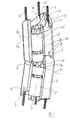
- the screwdriver shown in Fig. 1 for the intraoral Implantation has a handpiece 1 to which a elongated, multi-part screwdriver shaft 2 connects. At its end facing away from the handpiece 1 the screwdriver shaft 2 with an angular gear 3 a rotatable tool holder 4 connected, for example as a connection coupling for different Screwdriver blades is executed.
- a rotary drive is provided, which at illustrated embodiment from a manually operated Twist grip 5 exists, which has a screwdriver shaft 2 horizontal, multi-part drive shaft and the bevel gear 3 with the rotatable tool holder 4 is in a torque-transmitting connection.
- the screwdriver shaft 2 consists of several, relative shaft segments 6 pivotable relative to one another and is therefore flexible.
- the screwdriver shaft 2 can be used the screwdriver in any, through the articulated Connection of the shaft segments 6 approved shape as shown in Fig. 2, for example.
- each shaft segment 6 has Shank segment 6 at one end, for example that the end facing the handpiece 1, a concave, as a cylinder section trained sliding surface 7.
- each shaft segment 6 On his other End, for example facing the tool holder 4 End, each shaft segment 6 has a convex, sliding surface also formed by a cylinder section 8 on.
- the cylinder sections of the two sliding surfaces 7, 8 have the same radii so that the two sliding surfaces 7, 8 can slide flat on each other, as shown in Fig. 3 is.
- the axial directions 7a and 8a of the two die Sliding surfaces 7 and 8 forming cylinder sections are around the longitudinal axis 6a of each shaft segment 6 to each other by 90 ° transferred.
- each two diagonally opposite tensioning ropes 9 and 11 or 10 and 12 connected so that a Length compensation of this pair of tension cables 9 and 11 or 10 and 12 is made possible.
- all tensioning ropes 9-12 are included connected to a common clamping piece (not shown), that is longitudinally displaceable in the handpiece by means of a screw drive is. This allows all tension cables to be fixed of the screwdriver shaft 2 tense and also loosened become.
- the threaded drive of the clamping piece is, for example actuated by turning a rotating ring 14 on the handpiece 1.
- the drive shaft is in the area of the swiveling shaft segments 6 from individual shaft pieces 15 (Fig. 3), each in the connection area between two shaft segments 6 a shaft angle gear 16 articulated to each other Torque transmission are connected.
- Each shaft piece 15 is rotatably mounted in the associated shaft segment 6 and on provided at both ends with a spur gear 17, that of axially parallel, tapering drive pins 17a exists.
- the spur gears 17 adjacent Shaft pieces 15 interlock positively. Which Tapered shape of the trunnions 17a allows maintenance the meshing engagement even with an angle adjacent shaft pieces 6, as shown in Fig. 3.
- Each shaft piece 15 has a circumferential groove 18 into which a transverse pin 19 fastened in the shaft segment 6 tangentially intervenes. As a result, the rotatable shaft piece 15 in axial direction in the shaft segment 6 set.
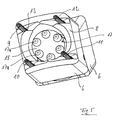
- the adjoining the tool holder 4, in Fig. 4 in The angle gear 3 shown in detail is a swivel angle gear executed that a pivoting of the tool holder 4 (those only partially shown in Fig. 4 is) opposite an end segment 20 of the screwdriver shaft 2 around a common transverse axis 21.
- Two Housing parts 22 and 23 of the bevel gear 3 are around common transverse axis 21 pivotable.
- Two transmission gears 24, 25 are independent of each other rotatable about the transverse axis 21 in the swivel angle gear 3 stored and are each with a spur gear 26 or 27 of the respective subsequent shaft pieces 15 or 28 in meshing engagement. Even if the swivel angle gear 3 from the straight line shown in Fig. 4 Position is pivoted about the transverse axis 21 is the rotational movement of the shaft piece 15 over the spur gear 26 and the two driven in opposite directions Transmission gears 24, 25 on the spur gear 27 of the shaft piece connected to the tool holder 4 28 transferred.
Landscapes
- Health & Medical Sciences (AREA)
- Oral & Maxillofacial Surgery (AREA)
- Dentistry (AREA)
- Epidemiology (AREA)
- Life Sciences & Earth Sciences (AREA)
- Animal Behavior & Ethology (AREA)
- General Health & Medical Sciences (AREA)
- Public Health (AREA)
- Veterinary Medicine (AREA)
- Orthopedic Medicine & Surgery (AREA)
- Dental Prosthetics (AREA)
- Dental Tools And Instruments Or Auxiliary Dental Instruments (AREA)
- Details Of Spanners, Wrenches, And Screw Drivers And Accessories (AREA)
Abstract
Description
in räumlicher Darstellungsweise,
Claims (8)
- Schraubendreher für die intraorale Implantation, mit einem Schraubendreherschaft, der an seinem einen Ende mit einem Handstück und an seinem anderen Ende über ein Winkelgetriebe mit einer drehbaren Werkzeugaufnahme verbunden ist, die über eine im Schraubendreherschaft drehbar aufgenommene Antriebswelle mit einem Drehantrieb am Handstück verbunden ist,
dadurch gekennzeichnet,
daß der Schraubendreherschaft (2) mindestens teilweise aus relativ zueinander schwenkbaren Schaftsegmenten (6) besteht, die durch eine gemeinsame, längsverlaufende Spannvorrichtung (9 - 14) zur Fixierung gegeneinander verspannbar sind, und daß die Antriebswelle im Bereich der Schaftsegmente (6) aus einzelnen Wellenstücken (15) besteht, die jeweils im Verbindungsbereich zweier Schaftsegmente (6) über ein Wellenwinkelgetriebe (16) miteinander zur Drehmomentübertragung verbunden sind. - Schraubendreher nach Anspruch 1,
dadurch gekennzeichnet,
daß jedes Schaftsegment (6) an seinem einen Ende eine konkave, einen Zylinderabschnitt bildende Gleitfläche (7) und an seinem anderen Ende eine konvexe, einen Zylinderabschnitt bildende Gleitfläche (8) aufweist, wobei die beiden Zylinderabschnitte gleiche Radien und um 90° zueinander versetzte Achsrichtungen aufweisen. - Schraubendreher nach Anspruch 1,
dadurch gekennzeichnet,
daß die gemeinsame Spannvorrichtung der Schaftsegmente (6) mindestens zwei Spannseile (9, 11 bzw. 10, 12) aufweist, die in jedem Schaftsegment (6) durch einander diagonal gegenüberliegende Spannkanäle (13) verlaufen. - Schraubendreher nach Anspruch 3,
dadurch gekennzeichnet,
daß zwei Paare von jeweils diagonal zueinander angeordneten Spannseilen (9, 11 bzw. 10, 12) vorgesehen sind und daß die beiden Spannseile (9, 11 bzw. 10, 12) jedes Paares an einem Ende zum Längenausgleich miteinander verbunden sind. - Schraubendreher nach Anspruch 3 oder 4,
dadurch gekennzeichnet,
daß alle Spannseile (9 - 12) mit einem im Handstück (1) mittels eines Gewindetriebs längsverschiebbaren Spannstück verbunden sind. - Schraubendreher nach Anspruch 1,
dadurch gekennzeichnet,
daß jedes Wellenstück (15) im zugeordneten Schaftsegment (6) drehbar gelagert ist und an seinen beiden Enden einen Verzahnungsstirnkranz (17) aus achsparallelen, sich verjüngenden Triebzapfen (17a) aufweist, wobei die Verzahnungsstirnkränze (17) benachbarter Wellenstücke (15) formschlüssig ineinandergreifen. - Schraubendreher nach Anspruch 1,
dadurch gekennzeichnet,
daß das an die Werkzeugaufnahme (4) anschließende Winkelgetriebe (3) ein Schwenkwinkelgetriebe ist und zwei um eine gemeinsame Querachse (21) schwenkbare Gehäuseteile (22, 23) aufweist, daß mindestens ein Übertragungszahnrad (24 bzw. 25) um die gemeinsame Querachse (21) drehbar gelagert ist und mit jeweils einem Verzahnungsstirnkranz (26, 27) der jeweils anschließenden Wellenstücke (15, 28) in Verzahnungseingriff steht. - Schraubendreher nach Anspruch 7, dadurch gekennzeichnet, daß zwei unabhängig voneinander um die Querachse (21) drehbare Übertragungszahnräder (24, 25) im Schwenkwinkelgetriebe (3) gelagert sind.
Applications Claiming Priority (2)
| Application Number | Priority Date | Filing Date | Title |
|---|---|---|---|
| DE10005137 | 2000-02-04 | ||
| DE10005137A DE10005137C2 (de) | 2000-02-04 | 2000-02-04 | Schraubendreher für die intraorale Implantation |
Publications (2)
| Publication Number | Publication Date |
|---|---|
| EP1121906A2 true EP1121906A2 (de) | 2001-08-08 |
| EP1121906A3 EP1121906A3 (de) | 2003-01-22 |
Family
ID=7629964
Family Applications (1)
| Application Number | Title | Priority Date | Filing Date |
|---|---|---|---|
| EP00127627A Withdrawn EP1121906A3 (de) | 2000-02-04 | 2000-12-16 | Schraubendreher für intraorale Implantation |
Country Status (3)
| Country | Link |
|---|---|
| US (1) | US6375462B2 (de) |
| EP (1) | EP1121906A3 (de) |
| DE (1) | DE10005137C2 (de) |
Cited By (12)
| Publication number | Priority date | Publication date | Assignee | Title |
|---|---|---|---|---|
| WO2011080104A1 (en) * | 2009-12-29 | 2011-07-07 | Straumann Holding Ag | Flexible dental screwdriver and method of manufacturing the same |
| WO2012129206A2 (en) | 2011-03-22 | 2012-09-27 | Depuy Spine, Inc. | Novel implant inserter having a laterally-extending dovetail engagement feature |
| US11497616B2 (en) | 2012-11-09 | 2022-11-15 | DePuy Synthes Products, Inc. | Interbody device with opening to allow packing graft and other biologics |
| US11529241B2 (en) | 2010-09-23 | 2022-12-20 | DePuy Synthes Products, Inc. | Fusion cage with in-line single piece fixation |
| US11607321B2 (en) | 2009-12-10 | 2023-03-21 | DePuy Synthes Products, Inc. | Bellows-like expandable interbody fusion cage |
| US11612491B2 (en) | 2009-03-30 | 2023-03-28 | DePuy Synthes Products, Inc. | Zero profile spinal fusion cage |
| US11660206B2 (en) | 2006-12-07 | 2023-05-30 | DePuy Synthes Products, Inc. | Intervertebral implant |
| US11678996B2 (en) | 2010-09-23 | 2023-06-20 | DePuy Synthes Products, Inc. | Stand alone intervertebral fusion device |
| US11806245B2 (en) | 2020-03-06 | 2023-11-07 | Eit Emerging Implant Technologies Gmbh | Expandable intervertebral implant |
| US11844702B2 (en) | 2012-03-06 | 2023-12-19 | DePuy Synthes Products, Inc. | Nubbed plate |
| USRE49973E1 (en) | 2013-02-28 | 2024-05-21 | DePuy Synthes Products, Inc. | Expandable intervertebral implant, system, kit and method |
| US12458505B2 (en) | 2006-12-22 | 2025-11-04 | Medos International Sarl | Composite vertebral spacers and instrument |
Families Citing this family (9)
| Publication number | Priority date | Publication date | Assignee | Title |
|---|---|---|---|---|
| DE20210696U1 (de) * | 2002-06-04 | 2002-10-31 | Carl Dillenius Metallwaren GmbH & Co., 75172 Pforzheim | Dental-Schraubwerkzeug |
| KR100671710B1 (ko) * | 2006-01-03 | 2007-02-12 | 이종호 | 자유각도의 임플란트 드라이버및 자유각도의 삽입구멍 임플란트 지대주 |
| US20090248092A1 (en) | 2008-03-26 | 2009-10-01 | Jonathan Bellas | Posterior Intervertebral Disc Inserter and Expansion Techniques |
| US9248028B2 (en) | 2011-09-16 | 2016-02-02 | DePuy Synthes Products, Inc. | Removable, bone-securing cover plate for intervertebral fusion cage |
| KR101408854B1 (ko) | 2014-04-15 | 2014-06-19 | 주식회사 디오 | 멤브레인 리프팅 장치 |
| US11779435B2 (en) * | 2015-08-26 | 2023-10-10 | Flexscrewdriver I.K.E. | Dental screwdriver |
| US10940016B2 (en) | 2017-07-05 | 2021-03-09 | Medos International Sarl | Expandable intervertebral fusion cage |
| ES1274629Y (es) * | 2021-06-07 | 2021-10-22 | Bienestar Bucal S L P | Dispositivo para atornillar implantes dentales |
| USD1034137S1 (en) | 2022-10-07 | 2024-07-09 | Milwaukee Electric Tool Corporation | Drill bit |
Family Cites Families (7)
| Publication number | Priority date | Publication date | Assignee | Title |
|---|---|---|---|---|
| US2501217A (en) * | 1945-10-24 | 1950-03-21 | Cleveland Pneumatic Tool Co | Adjustable drive shaft |
| US4281989A (en) * | 1979-06-25 | 1981-08-04 | The Idea Syndicate, Inc. | Articulated dental hand piece |
| DE8607407U1 (de) * | 1986-03-18 | 1986-05-07 | Gebr. Wagschal GmbH & Co KG, 2804 Lilienthal | Eindrehinstrument zum Eindrehen von Zahnimplantaten |
| US5129823A (en) * | 1991-10-08 | 1992-07-14 | R & J Innovations, Inc. | Driver tool and method for implant dentistry |
| US5455997A (en) * | 1992-08-31 | 1995-10-10 | Nasiell; Gustav | Threading initiation method |
| DE29512090U1 (de) * | 1995-07-27 | 1995-11-23 | Schwartz, Werner, Dipl.-Ing., 25469 Halstenbek | Schraubinstrument für den Dentalbereich |
| US6145413A (en) * | 1998-09-14 | 2000-11-14 | Lin; Ching Chou | Multifunction tool |
-
2000
- 2000-02-04 DE DE10005137A patent/DE10005137C2/de not_active Expired - Fee Related
- 2000-12-16 EP EP00127627A patent/EP1121906A3/de not_active Withdrawn
-
2001
- 2001-01-19 US US09/764,138 patent/US6375462B2/en not_active Expired - Fee Related
Cited By (18)
| Publication number | Priority date | Publication date | Assignee | Title |
|---|---|---|---|---|
| US11712345B2 (en) | 2006-12-07 | 2023-08-01 | DePuy Synthes Products, Inc. | Intervertebral implant |
| US11660206B2 (en) | 2006-12-07 | 2023-05-30 | DePuy Synthes Products, Inc. | Intervertebral implant |
| US12458505B2 (en) | 2006-12-22 | 2025-11-04 | Medos International Sarl | Composite vertebral spacers and instrument |
| US12097124B2 (en) | 2009-03-30 | 2024-09-24 | DePuy Synthes Products, Inc. | Zero profile spinal fusion cage |
| US11612491B2 (en) | 2009-03-30 | 2023-03-28 | DePuy Synthes Products, Inc. | Zero profile spinal fusion cage |
| US11607321B2 (en) | 2009-12-10 | 2023-03-21 | DePuy Synthes Products, Inc. | Bellows-like expandable interbody fusion cage |
| WO2011080104A1 (en) * | 2009-12-29 | 2011-07-07 | Straumann Holding Ag | Flexible dental screwdriver and method of manufacturing the same |
| US11382768B2 (en) | 2010-09-23 | 2022-07-12 | DePuy Synthes Products, Inc. | Implant inserter having a laterally-extending dovetail engagement feature |
| US11529241B2 (en) | 2010-09-23 | 2022-12-20 | DePuy Synthes Products, Inc. | Fusion cage with in-line single piece fixation |
| US11678996B2 (en) | 2010-09-23 | 2023-06-20 | DePuy Synthes Products, Inc. | Stand alone intervertebral fusion device |
| US12109127B2 (en) | 2010-09-23 | 2024-10-08 | DePuy Synthes Products, Inc. | Implant inserter having a laterally-extending dovetail engagement feature |
| AU2012231117B2 (en) * | 2011-03-22 | 2016-03-03 | Depuy Spine, Inc. | Novel implant inserter having a laterally-extending dovetail engagement feature |
| EP2688520A4 (de) * | 2011-03-22 | 2015-04-29 | Depuy Synthes Products Llc | Neuer implantateinsetzer mit einer seitendehnungs-schwalbenschwanz-einrastfunktion |
| WO2012129206A2 (en) | 2011-03-22 | 2012-09-27 | Depuy Spine, Inc. | Novel implant inserter having a laterally-extending dovetail engagement feature |
| US11844702B2 (en) | 2012-03-06 | 2023-12-19 | DePuy Synthes Products, Inc. | Nubbed plate |
| US11497616B2 (en) | 2012-11-09 | 2022-11-15 | DePuy Synthes Products, Inc. | Interbody device with opening to allow packing graft and other biologics |
| USRE49973E1 (en) | 2013-02-28 | 2024-05-21 | DePuy Synthes Products, Inc. | Expandable intervertebral implant, system, kit and method |
| US11806245B2 (en) | 2020-03-06 | 2023-11-07 | Eit Emerging Implant Technologies Gmbh | Expandable intervertebral implant |
Also Published As
| Publication number | Publication date |
|---|---|
| US20010024779A1 (en) | 2001-09-27 |
| EP1121906A3 (de) | 2003-01-22 |
| DE10005137A1 (de) | 2001-08-16 |
| DE10005137C2 (de) | 2002-11-07 |
| US6375462B2 (en) | 2002-04-23 |
Similar Documents
| Publication | Publication Date | Title |
|---|---|---|
| EP1121906A2 (de) | Schraubendreher für intraorale Implantation | |
| DE2855797C3 (de) | Zahnärztliche Handstückanordnung | |
| DE1026134B (de) | Vorrichtung zur loesbaren Sicherung von Raedern gegen Axialverschiebung | |
| EP1277533A1 (de) | Spannvorrichtung für die rotatorische Bearbeitung von Werkstücken | |
| DE102008029301A1 (de) | Endoskop- und Schaftsystem | |
| DE3943403A1 (de) | Endoskop, insbesondere technisches endoskop | |
| DE3923609A1 (de) | Winkelantriebsvorrichtung | |
| DE3823746C2 (de) | ||
| EP1227759B1 (de) | Drehgelenk für medizinische instrumente | |
| EP4376730B1 (de) | Chirurgisches instrument und lenkgetriebe dafür | |
| DE102004046539B4 (de) | Chirurgisches Instrument | |
| EP4376728B1 (de) | Chirurgisches instrument und lenkgetriebe dafür | |
| EP0768408B1 (de) | Greiferantrieb für eine Webmaschine | |
| EP0581037B1 (de) | Ärztliches oder zahnärztliches Behandlungsinstrument mit einem angetriebenen Behandlungswerkzeug | |
| DE2035793B1 (de) | Getriebeschraubenschlüssel | |
| DE102022211977B3 (de) | Operationsinstrument-klemmvorrichtung und schnelllöse- und antriebsgerät derselben | |
| DE102017118571B4 (de) | Winkelgetriebe | |
| DE3905633C2 (de) | ||
| EP0627975A1 (de) | Vorrichtung zum manipulieren von gegenständen. | |
| DE19850108B4 (de) | Dentalinstrument | |
| DE69015644T2 (de) | Rohrenbearbeitungswerkzeug mit verbesserung des torsionsverhaltens und der spannmoeglichkeiten. | |
| DE2855796A1 (de) | Zahnaerztliche handstueckanordnung | |
| DE3616731C2 (de) | ||
| DE102023121570B4 (de) | Schraubendreher für eine Innenprofilschraube | |
| DE3631198C2 (de) | Chirurgisches Instrument |
Legal Events
| Date | Code | Title | Description |
|---|---|---|---|
| PUAI | Public reference made under article 153(3) epc to a published international application that has entered the european phase |
Free format text: ORIGINAL CODE: 0009012 |
|
| 17P | Request for examination filed |
Effective date: 20001216 |
|
| AK | Designated contracting states |
Kind code of ref document: A2 Designated state(s): AT BE CH CY DE DK ES FI FR GB GR IE IT LI LU MC NL PT SE TR |
|
| AX | Request for extension of the european patent |
Free format text: AL;LT;LV;MK;RO;SI |
|
| RIN1 | Information on inventor provided before grant (corrected) |
Inventor name: KOEHLER, CARSTEN GEORG Inventor name: HOLWEG, ANDREAS, DR. Inventor name: KREMER, EGBERT |
|
| PUAL | Search report despatched |
Free format text: ORIGINAL CODE: 0009013 |
|
| AK | Designated contracting states |
Kind code of ref document: A3 Designated state(s): AT BE CH CY DE DK ES FI FR GB GR IE IT LI LU MC NL PT SE TR |
|
| AX | Request for extension of the european patent |
Free format text: AL;LT;LV;MK;RO;SI |
|
| RAP1 | Party data changed (applicant data changed or rights of an application transferred) |
Owner name: DEGUSSA DENTAL GMBH |
|
| AKX | Designation fees paid |
Designated state(s): DE ES FR GB IT |
|
| RAP1 | Party data changed (applicant data changed or rights of an application transferred) |
Owner name: DEGUDENT GMBH |
|
| GRAP | Despatch of communication of intention to grant a patent |
Free format text: ORIGINAL CODE: EPIDOSNIGR1 |
|
| STAA | Information on the status of an ep patent application or granted ep patent |
Free format text: STATUS: THE APPLICATION IS DEEMED TO BE WITHDRAWN |
|
| 18D | Application deemed to be withdrawn |
Effective date: 20050219 |