EP0500546B1 - Verrouillage pour un tiroir enfichable - Google Patents
Verrouillage pour un tiroir enfichable Download PDFInfo
- Publication number
- EP0500546B1 EP0500546B1 EP90913814A EP90913814A EP0500546B1 EP 0500546 B1 EP0500546 B1 EP 0500546B1 EP 90913814 A EP90913814 A EP 90913814A EP 90913814 A EP90913814 A EP 90913814A EP 0500546 B1 EP0500546 B1 EP 0500546B1
- Authority
- EP
- European Patent Office
- Prior art keywords
- plug
- locking
- slider
- locking device
- slide
- Prior art date
- Legal status (The legal status is an assumption and is not a legal conclusion. Google has not performed a legal analysis and makes no representation as to the accuracy of the status listed.)
- Expired - Lifetime
Links
- 230000009471 action Effects 0.000 claims description 8
- 238000009434 installation Methods 0.000 claims description 2
- 238000006073 displacement reaction Methods 0.000 description 4
- 241001295925 Gegenes Species 0.000 description 2
- 230000008878 coupling Effects 0.000 description 2
- 238000010168 coupling process Methods 0.000 description 2
- 238000005859 coupling reaction Methods 0.000 description 2
- 238000003780 insertion Methods 0.000 description 2
- 230000037431 insertion Effects 0.000 description 2
- 230000001154 acute effect Effects 0.000 description 1
- 230000000903 blocking effect Effects 0.000 description 1
- 230000000694 effects Effects 0.000 description 1
- 230000003993 interaction Effects 0.000 description 1
- 238000000034 method Methods 0.000 description 1
- 230000008569 process Effects 0.000 description 1
Images

Classifications
-
- H—ELECTRICITY
- H02—GENERATION; CONVERSION OR DISTRIBUTION OF ELECTRIC POWER
- H02B—BOARDS, SUBSTATIONS OR SWITCHING ARRANGEMENTS FOR THE SUPPLY OR DISTRIBUTION OF ELECTRIC POWER
- H02B11/00—Switchgear having carriage withdrawable for isolation
- H02B11/12—Switchgear having carriage withdrawable for isolation with isolation by horizontal withdrawal
- H02B11/127—Withdrawal mechanism
- H02B11/133—Withdrawal mechanism with interlock
Definitions
- the invention relates to a device for locking an insert in the insert compartment of a control cabinet according to the preamble of claim 1.
- Devices of this type are used to lock inserts which are equipped with switching devices or the like at certain insertion depths.
- the positions "operating position”, test position “and” disconnected position " which relate to the electrical connection of the switching devices arranged in the plug-in unit with the busbars and auxiliary circuits in the control cabinet, are fixed by these devices.
- the plug-in unit should only be able to be moved from one position to the next when the switch is switched off. Therefore, there is a requirement that the lock of the insert can only be released when the switching device is switched off. Conversely, the switching device should also not be able to be switched on when the lock is released (for example in an intermediate position).
- a locking device for locking an insert which blocked the insert in the predetermined positions by means of a rack and pinion, in which two racks are driven by a pinion.
- One of the racks has recesses into which one cooperates with the switching shaft of the switching device Locking rod engages and the rack blocks its movement when the switch is turned on.
- the connection between the switch and the locking device is rigid and the installation location of the switch is tied to the direction of movement of the locking rod.
- DE-AS 27 49 003 A more flexible solution is described by DE-AS 27 49 003.
- the device for locking the switch is connected to the switch via a Bowden cable.
- This device also has an adjustment element for actuating the insert, which fixes the different latching positions.
- the invention has for its object to improve a device for locking an insert in such a way that safe handling of the insert with locking in the individual positions and in addition a mutual blocking of a switch and the locking device takes place with little effort.
- the device for locking an insert consists of a support element fastened to the insert, in which a latch is displaceable and is mounted under the action of a spring.
- the bolt engages with one end in the locking openings of the slide-in guide of the control cabinet, while it is coupled via a pin to a closer also mounted in the carrier element, in that the pin arranged on the bolt projects into a recess in the slide arranged obliquely to the direction of movement.
- the slide is advantageously actuated by an operating element arranged on the handle of the insert, said operating element having a perforation which interacts with a row of holes in the handle in such a way that the operating element in both the unlocked and in the locked position by means of e.g. Padlocks is lockable.
- a further advantageous embodiment of the invention can be that the different positions can be combined with different switch functions by coding the bolt to different latching openings, e.g. Test position.
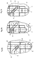
- 3a shows the lowest position of the latch 40. In this position the insert is locked by the latch 40 engaging in the latching opening 10 of the insert guide 2.
- the pin 42 of the bolt 40 is located at the deepest point of the recess 31 of the slide 30.
- FIG. 3b shows the latched position of the bolt.
- the pin 42 engages behind the latching lug 32 and remains here until the latch 40 is raised by a cam 8 or the like.
- the pin 42 on the contact edge 39 with the latching lug 32 is made at an acute angle.
- FIG. 3c shows the unlocked position of the latch 40.
- the latch 40 slides on the slide-in guide 2 as shown in FIG. 4 and is ready to dive into the next latching opening in the direction of displacement and to lock the slide-in.
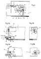
- FIG. 4 shows the arrangement of the locking device 20 in an insert 1, which is displaceable in an insert guide 2 is arranged.
- the locking device 20 is fastened to the wall of the insert by means of the bore 25 in such a way that the sliding tab 33 of the slide 30 interacts with an actuating element 5 of a handle 4 arranged on the front of the insert.
- the latch 40 engages with its lower end 41 in a latching opening 10c in the insert guide 2.
- the latching openings 10a, 10b and 10c in the insert guide 2 are assigned to the positions of the insert “disconnected position", "test position” and "operating position".
- cams 8a, 8b and 8c are arranged on the slide-in guide, which cooperate with the lower end 41 of the bolt 40 during the displacement of the slide-in 1.
- FIG. 5a shows a detail from FIG. 5a in the viewing direction X.
- the switching device 3 has a locking disk 7 on the drive axle, in the cutout 17 of which a locking slide 14 can engage.
- the locking slide 14 is connected by means of a Bowden cable 6 to the locking device 20 in such a way that the Bowden cable 6 is fastened to the carrier element 21 and the plunger 19 actuating the Bowden cable rests on the sliding tab 33.
- the locking device 20 is fastened to the side wall of the insert 1 by means of the screw 16.
- the handle 4, in which the actuating element 5 acting on the sliding tab 33 is arranged, is located on the front of the insert.
- the actuating element 5 has bores 11a, 11b and 11c which are aligned with bores 12a, 12b and 12c in the handle 4 in the non-actuated position. This allows the actuator 5 with the handle 4th secure against unauthorized use with up to three security locks 13.
- the mode of operation is now as follows.
- the switching device 3 When the switching device 3 is brought into the off position, the cutout 17 of the locking disk 7 is aligned with the locking slide 14 of the Bowden cable. If the actuating element 5 is now moved on the handle 4, this acts on the sliding tab 33.
- the slider 30 is actuated, the bolt 40 is lifted out of the latching opening 10a via the oblique recess 31 and the pin 42, and the pin 42 snaps onto the latching lug 32 a.
- the locking slide 14 has been simultaneously moved into the cutout 17 of the locking disk 7 via the plunger 19 of the Bowden cable 6.
- the switching device 3 can no longer be switched to the on position.
- the insert 1 can be moved into another position.
- the bar 40 is briefly lifted from the next passed cam 8 and released from the latch between the pin 42 and the latching lug 32 and the slide slides on the insertion guide (FIG. 3). Under the action of the spring rod 44, the latch snaps into the next one Locking opening 10 a.
- the slider 30 moves back to the starting position.
- the plunger 19 and the Bowden cable 6 follow this movement and the locking slide 14 releases the locking disk 7.
- the switching device 3 can be switched again. In the switched-on position of the switching device 3, the movement of the locking slide 14 is blocked by the locking disk 7, since the recess 17 and the locking slide 14 are no longer in alignment.
- the slide 30 is blocked by the plunger 19. This means that the insert 1 can no longer be moved out of the locked position as long as the switching device 3 is in the setting.
- 6a and 6b show a further possibility of coupling a switching device 3a to the locking device 20.
- the switching device 3a is at such a distance from the locking device 20 that a locking angle 34 interacts with a locking disk 7a when the slide 30 is actuated.
- 6b shows the view in the y direction.
- the locking bracket 34 has a nose 14a, which can engage in the cutout 17a of the locking disk 7a. As described for FIG. 5, this is only possible in the off position of the switching device 3a.
Landscapes
- Engineering & Computer Science (AREA)
- Power Engineering (AREA)
- Details Of Connecting Devices For Male And Female Coupling (AREA)
- Lock And Its Accessories (AREA)
- Vending Machines For Individual Products (AREA)
- Control Of Motors That Do Not Use Commutators (AREA)
- Coupling Device And Connection With Printed Circuit (AREA)
- Trip Switchboards (AREA)
Claims (6)
- Dispositif de verrouillage (20) destiné à un ensemble connectable (1), qui est inséré dans le compartiment à tiroir d'une armoire de commande ou d'une installation similaire et qui est encliqueté dans des positions d'insertion précises, dépendants de la fonction, le dispositif de verrouillage (20) pouvant être déverrouillé à partir de l'extérieur, étant cependant encliquetable de façon automatique dans les positions d'encliquetage individuelles, un interrupteur principal installé à l'intérieur de l'ensemble connectable ne pouvant être actionné qu'en position verrouillée, caractérisé en ce qu'un verrou (40) est logé coulissant, et sous l'action d'un ressort (44), à l'intérieur d'un cadre porteur (21) attaché à l'ensemble connectable (1) et entre avec une de ses extrémités (41) dans des ouvertures d'encliquetage (10a, 10b, ou 10c) assignées aux positions d'encliquetage dans la glissière (2) de l'ensemble connectable, le verrou (40) étant couplé à un coulisseau (30), qui est disposé de façon mobile et verticalement par rapport à la direction de mouvement du verrou (40), grâce au fait qu'un pivot (42) aménagé sur le verrou (40) s'étend dans un évidement (31) aménagé dans le coulisseau (30) de façon inclinée par rapport à la direction de mouvement.
- Dispositif de verrouillage selon la revendication 1, caractérisé en ce que l'évidement (31) aménagé dans le coulisseau (30) de façon inclinée par rapport à la direction de mouvement comporte un ergot d'encliquetage (32) qui assure l'encliquetage du pivot (42) du verrou (40) en position déverrouillée, lorsque le coulisseau (30) est actionné dans le sens d'un déverrouillage.
- Dispositif de verrouillage selon l'une quelconque des revendications 1 ou 2, caractérisé en ce que des cames (8a, 8b, 8c) assignées aux positions d'encliquetage sont prévues sur la glissière (2) de l'ensemble connectable, cames qui soulèvent le verrou (40) au cours du déplacement de l'ensemble connectable (1) et le dégagent de l'encliquetage, le coulisseau (30) étant sous l'action d'un ressort (37), qui agit sur le coulisseau (30) dans le sens d'un rappel.
- Dispositif de verrouillage selon l'une quelconque des revendications 1 à 3, caractérisé en ce que le coulisseau (30) se trouve sous l'action d'un élément de commande (5) qui comporte une rangée de perforations (11a, 11b, 11c), qui est alignée sur une rangée de perforations (12a, 12b, 12c) se trouvant dans la manette (4) de telle manière que l'élément de commande (5) soit susceptible d'être fermé au moyen d'un maximum de trois serrures à étrier.
- Dispositif de verrouillage selon l'une quelconque des revendications 1 à 3, caractérisé en ce que le coulisseau (30) comporte une éclisse de forme angulaire (33) qui coopère avec une tige (19) montée sur le cadre porteur (21), tige qui, par l'intermédiaire d'une transmission par Bowden (6), déplace un coulisseau d'arrêt (14) dans la partie découpée (17) d'un disque d'arrêt (7).
- Dispositif de verrouillage selon l'une quelconque des revendications 1 à 4, caractérisé en ce qu'un angle d'arrêt (34) est prévu sur le coulisseau (30), angle qui comporte une came (14a) qui coopère avec un disque d'arrêt (7a) d'un appareil de couplage (3a) disposé à côté du dispositif de verrouillage (20) de telle manière que, en position ouverte de l'appareil de couplage (3a), la came (14a) entre dans un évidement (17a) du disque d'arrêt (7a) et empêche la mise en position fermée de l'appareil de couplage.
Applications Claiming Priority (3)
| Application Number | Priority Date | Filing Date | Title |
|---|---|---|---|
| DE3928101 | 1989-08-25 | ||
| DE3928101 | 1989-08-25 | ||
| PCT/EP1990/001392 WO1991003088A1 (fr) | 1989-08-25 | 1990-08-22 | Verrouillage pour un tiroir enfichable |
Publications (2)
| Publication Number | Publication Date |
|---|---|
| EP0500546A1 EP0500546A1 (fr) | 1992-09-02 |
| EP0500546B1 true EP0500546B1 (fr) | 1994-06-22 |
Family
ID=6387853
Family Applications (1)
| Application Number | Title | Priority Date | Filing Date |
|---|---|---|---|
| EP90913814A Expired - Lifetime EP0500546B1 (fr) | 1989-08-25 | 1990-08-22 | Verrouillage pour un tiroir enfichable |
Country Status (5)
| Country | Link |
|---|---|
| EP (1) | EP0500546B1 (fr) |
| AT (1) | ATE107803T1 (fr) |
| AU (1) | AU6405490A (fr) |
| DE (1) | DE59006256D1 (fr) |
| WO (1) | WO1991003088A1 (fr) |
Families Citing this family (6)
| Publication number | Priority date | Publication date | Assignee | Title |
|---|---|---|---|---|
| DE4204238C2 (de) * | 1992-02-13 | 2000-06-21 | Moeller Gmbh | Einschub mit einer schaltbaren NH-Sicherungsleiste für Einschubverteiler |
| DE19511329A1 (de) * | 1995-03-28 | 1996-10-02 | Abb Patent Gmbh | Baugruppen-Befestigungssystem |
| DE19641513C1 (de) * | 1996-09-27 | 1998-04-09 | Siemens Ag | Abschließeinrichtung zur Sperrung der Betätigung eines Fahrantriebes eines Leistungsschalters |
| DE19647747C1 (de) * | 1996-11-06 | 1998-04-09 | Siemens Ag | Einschiebbarer Geräteträger mit einer Verriegelungseinrichtung |
| DE10061783C1 (de) * | 2000-12-12 | 2002-06-06 | Moeller Gmbh | Verriegelungsvorrichtung |
| DE102006052717A1 (de) * | 2006-11-08 | 2008-05-15 | Cooper Crouse-Hinds Gmbh | Steckgehäusemodul |
Family Cites Families (3)
| Publication number | Priority date | Publication date | Assignee | Title |
|---|---|---|---|---|
| DE1029070B (de) * | 1954-03-11 | 1958-04-30 | Voigt & Haeffner Ag | Ausfahrbarer Niederspannungs-Leistungsschalter |
| US4020301A (en) * | 1975-04-14 | 1977-04-26 | General Electric Company | Drawout apparatus having improved secondary contact mounting provisions |
| US4489362A (en) * | 1983-03-01 | 1984-12-18 | General Electric Company | Electric switchboard apparatus with a breaker-fuse interlock |
-
1990
- 1990-08-22 DE DE59006256T patent/DE59006256D1/de not_active Expired - Fee Related
- 1990-08-22 WO PCT/EP1990/001392 patent/WO1991003088A1/fr not_active Ceased
- 1990-08-22 AU AU64054/90A patent/AU6405490A/en not_active Abandoned
- 1990-08-22 AT AT90913814T patent/ATE107803T1/de not_active IP Right Cessation
- 1990-08-22 EP EP90913814A patent/EP0500546B1/fr not_active Expired - Lifetime
Also Published As
| Publication number | Publication date |
|---|---|
| AU6405490A (en) | 1991-04-03 |
| ATE107803T1 (de) | 1994-07-15 |
| WO1991003088A1 (fr) | 1991-03-07 |
| EP0500546A1 (fr) | 1992-09-02 |
| DE59006256D1 (de) | 1994-07-28 |
Similar Documents
| Publication | Publication Date | Title |
|---|---|---|
| EP1380082B1 (fr) | Installation de commutation basse tension comportant un dispositif de verrouillage pour module d'appareils | |
| EP0563530B1 (fr) | Dispositif de commutation de puissance | |
| DE102007024977A1 (de) | Frontbaugruppe, Geräteträger mit einer derartigen Frontbaugruppe sowie Schaltschrank mit einer Vielzahl derartiger Geräteträger | |
| DE29506151U1 (de) | Sicherungsvorrichtung für ein auf eine Montagefläche montierbares Schaltgerät mit Schaltschloß | |
| EP0695472B1 (fr) | Installation de distribution electrique basse tension avec un support d'appareils et un dispositif de contact disjoncteur | |
| EP2020011B1 (fr) | Appareil de commutation pour installation de distribution électrique pour la distribution d'electricite | |
| DE2433322A1 (de) | Mehrfallen-panikverschluss | |
| DE2025504C3 (de) | Schiebetastenschalteranordnung | |
| DE10216594A1 (de) | Schaltschrank mit Einschubkassette | |
| WO1996023338A2 (fr) | Dispositif pour influer sur un organe de translation d'un appareil de commutation | |
| DE19534609C2 (de) | Selbstverriegelndes Motorschloss | |
| DE102008014369B4 (de) | Türschloss mit einer elektromagnetischen Offenhaltung | |
| DE102010011204A1 (de) | Schaltschrank und Geräteträger für einen Schaltschrank | |
| EP0228987B1 (fr) | Dispositif de verrouillage d'un appareil commutateur monté d'une façon déplaçable | |
| WO1991003088A1 (fr) | Verrouillage pour un tiroir enfichable | |
| DE3931101C2 (fr) | ||
| DE3909061A1 (de) | Sperrvorrichtung gegen gleichzeitiges einschalten zweier mechanisch oder elektromagnetisch betaetigter schaltorgane | |
| EP0799960B1 (fr) | Ferrure pour vantail de fenêtre, porte, ou similaire pouvant être basculée et par la suite être au moins déplacée selon un plan parallèle | |
| DE3501297A1 (de) | Motorzentralverteilung | |
| EP2998475A1 (fr) | Levier de jour pour une serrure à battant passif | |
| DE102016004835B4 (de) | Sicherheitsschalter | |
| EP4229260B1 (fr) | Dispositif de verrouillage destiné à des parties de meuble mobiles | |
| DE3414642A1 (de) | Blockschloss | |
| DE3113054A1 (de) | Magnetschiebeschloss | |
| DE9321038U1 (de) | Selbstverriegelndes Sicherheitstürschloß |
Legal Events
| Date | Code | Title | Description |
|---|---|---|---|
| PUAI | Public reference made under article 153(3) epc to a published international application that has entered the european phase |
Free format text: ORIGINAL CODE: 0009012 |
|
| 17P | Request for examination filed |
Effective date: 19920612 |
|
| AK | Designated contracting states |
Kind code of ref document: A1 Designated state(s): AT BE CH DE FR GB LI NL |
|
| 17Q | First examination report despatched |
Effective date: 19931201 |
|
| GRAA | (expected) grant |
Free format text: ORIGINAL CODE: 0009210 |
|
| AK | Designated contracting states |
Kind code of ref document: B1 Designated state(s): AT BE CH DE FR GB LI NL |
|
| PG25 | Lapsed in a contracting state [announced via postgrant information from national office to epo] |
Ref country code: NL Effective date: 19940622 Ref country code: BE Effective date: 19940622 |
|
| REF | Corresponds to: |
Ref document number: 107803 Country of ref document: AT Date of ref document: 19940715 Kind code of ref document: T |
|
| REF | Corresponds to: |
Ref document number: 59006256 Country of ref document: DE Date of ref document: 19940728 |
|
| GBT | Gb: translation of ep patent filed (gb section 77(6)(a)/1977) |
Effective date: 19940908 |
|
| ET | Fr: translation filed | ||
| NLV1 | Nl: lapsed or annulled due to failure to fulfill the requirements of art. 29p and 29m of the patents act | ||
| PLBE | No opposition filed within time limit |
Free format text: ORIGINAL CODE: 0009261 |
|
| STAA | Information on the status of an ep patent application or granted ep patent |
Free format text: STATUS: NO OPPOSITION FILED WITHIN TIME LIMIT |
|
| 26N | No opposition filed | ||
| PGFP | Annual fee paid to national office [announced via postgrant information from national office to epo] |
Ref country code: AT Payment date: 20010725 Year of fee payment: 12 |
|
| REG | Reference to a national code |
Ref country code: GB Ref legal event code: IF02 |
|
| PGFP | Annual fee paid to national office [announced via postgrant information from national office to epo] |
Ref country code: GB Payment date: 20020724 Year of fee payment: 13 |
|
| PGFP | Annual fee paid to national office [announced via postgrant information from national office to epo] |
Ref country code: CH Payment date: 20020726 Year of fee payment: 13 |
|
| PG25 | Lapsed in a contracting state [announced via postgrant information from national office to epo] |
Ref country code: AT Free format text: LAPSE BECAUSE OF NON-PAYMENT OF DUE FEES Effective date: 20020822 |
|
| PG25 | Lapsed in a contracting state [announced via postgrant information from national office to epo] |
Ref country code: GB Free format text: LAPSE BECAUSE OF NON-PAYMENT OF DUE FEES Effective date: 20030822 |
|
| PG25 | Lapsed in a contracting state [announced via postgrant information from national office to epo] |
Ref country code: LI Free format text: LAPSE BECAUSE OF NON-PAYMENT OF DUE FEES Effective date: 20030831 Ref country code: CH Free format text: LAPSE BECAUSE OF NON-PAYMENT OF DUE FEES Effective date: 20030831 |
|
| GBPC | Gb: european patent ceased through non-payment of renewal fee | ||
| REG | Reference to a national code |
Ref country code: CH Ref legal event code: PL |
|
| PGFP | Annual fee paid to national office [announced via postgrant information from national office to epo] |
Ref country code: DE Payment date: 20040805 Year of fee payment: 15 |
|
| PGFP | Annual fee paid to national office [announced via postgrant information from national office to epo] |
Ref country code: FR Payment date: 20040809 Year of fee payment: 15 |
|
| PG25 | Lapsed in a contracting state [announced via postgrant information from national office to epo] |
Ref country code: DE Free format text: LAPSE BECAUSE OF NON-PAYMENT OF DUE FEES Effective date: 20060301 |
|
| PG25 | Lapsed in a contracting state [announced via postgrant information from national office to epo] |
Ref country code: FR Free format text: LAPSE BECAUSE OF NON-PAYMENT OF DUE FEES Effective date: 20060428 |
|
| REG | Reference to a national code |
Ref country code: FR Ref legal event code: ST Effective date: 20060428 |