EP0500563B1 - Imprimante a jet d'encre avec tetes d'impression interchangeables - Google Patents
Imprimante a jet d'encre avec tetes d'impression interchangeables Download PDFInfo
- Publication number
- EP0500563B1 EP0500563B1 EP90915307A EP90915307A EP0500563B1 EP 0500563 B1 EP0500563 B1 EP 0500563B1 EP 90915307 A EP90915307 A EP 90915307A EP 90915307 A EP90915307 A EP 90915307A EP 0500563 B1 EP0500563 B1 EP 0500563B1
- Authority
- EP
- European Patent Office
- Prior art keywords
- ink
- printing unit
- print heads
- printing
- ink print
- Prior art date
- Legal status (The legal status is an assumption and is not a legal conclusion. Google has not performed a legal analysis and makes no representation as to the accuracy of the status listed.)
- Expired - Lifetime
Links
- 238000007639 printing Methods 0.000 title claims abstract description 80
- 230000007246 mechanism Effects 0.000 title abstract description 6
- 239000000976 ink Substances 0.000 claims description 147
- 230000008878 coupling Effects 0.000 claims description 9
- 238000010168 coupling process Methods 0.000 claims description 9
- 238000005859 coupling reaction Methods 0.000 claims description 9
- 238000003780 insertion Methods 0.000 claims description 9
- 230000037431 insertion Effects 0.000 claims description 9
- 239000004020 conductor Substances 0.000 claims description 5
- 239000011888 foil Substances 0.000 claims description 5
- 239000013013 elastic material Substances 0.000 claims description 3
- 238000010276 construction Methods 0.000 claims description 2
- 238000013461 design Methods 0.000 abstract description 4
- 239000007921 spray Substances 0.000 description 9
- 238000010438 heat treatment Methods 0.000 description 8
- 238000000034 method Methods 0.000 description 7
- 239000012530 fluid Substances 0.000 description 6
- 230000008569 process Effects 0.000 description 5
- 239000000758 substrate Substances 0.000 description 4
- 230000015572 biosynthetic process Effects 0.000 description 3
- 239000003086 colorant Substances 0.000 description 3
- 239000011159 matrix material Substances 0.000 description 3
- 238000000926 separation method Methods 0.000 description 3
- 230000008901 benefit Effects 0.000 description 2
- 230000008859 change Effects 0.000 description 2
- 238000004140 cleaning Methods 0.000 description 2
- 238000011109 contamination Methods 0.000 description 2
- 238000001035 drying Methods 0.000 description 2
- 229920001971 elastomer Polymers 0.000 description 2
- 239000000806 elastomer Substances 0.000 description 2
- 238000007641 inkjet printing Methods 0.000 description 2
- 230000007257 malfunction Effects 0.000 description 2
- 229910052751 metal Inorganic materials 0.000 description 2
- 239000002184 metal Substances 0.000 description 2
- 238000012544 monitoring process Methods 0.000 description 2
- 238000007789 sealing Methods 0.000 description 2
- 230000032683 aging Effects 0.000 description 1
- 229910052782 aluminium Inorganic materials 0.000 description 1
- XAGFODPZIPBFFR-UHFFFAOYSA-N aluminium Chemical compound [Al] XAGFODPZIPBFFR-UHFFFAOYSA-N 0.000 description 1
- 238000006243 chemical reaction Methods 0.000 description 1
- 238000011161 development Methods 0.000 description 1
- 230000018109 developmental process Effects 0.000 description 1
- 239000000428 dust Substances 0.000 description 1
- 238000001704 evaporation Methods 0.000 description 1
- 230000008020 evaporation Effects 0.000 description 1
- 239000011521 glass Substances 0.000 description 1
- 238000002347 injection Methods 0.000 description 1
- 239000007924 injection Substances 0.000 description 1
- 239000007788 liquid Substances 0.000 description 1
- 230000005499 meniscus Effects 0.000 description 1
- 239000007769 metal material Substances 0.000 description 1
- 239000002245 particle Substances 0.000 description 1
- 230000007704 transition Effects 0.000 description 1
Images

Classifications
-
- B—PERFORMING OPERATIONS; TRANSPORTING
- B41—PRINTING; LINING MACHINES; TYPEWRITERS; STAMPS
- B41J—TYPEWRITERS; SELECTIVE PRINTING MECHANISMS, i.e. MECHANISMS PRINTING OTHERWISE THAN FROM A FORME; CORRECTION OF TYPOGRAPHICAL ERRORS
- B41J25/00—Actions or mechanisms not otherwise provided for
- B41J25/34—Bodily-changeable print heads or carriages
Definitions
- the invention relates to an ink printing unit with interchangeable print heads according to the preamble of patent claim 1.
- a printhead structure for use in ink writing devices, a printhead structure is known (DE-OS 28 43 064), in which a plurality of outlet nozzles arranged in high density are provided, from which individual ink droplets are ejected and thrown against a recording medium.
- the droplet ejection in such a drop-on-demand print head takes place under the influence of thermoelectric conversion elements.
- thermoelectric conversion elements These are arranged in the form of heating resistors on a substrate, can be controlled individually and are assigned to individual ink channels. When a heating resistor is activated, an ink vapor bubble is generated in the relevant ink channel, which leads to the ejection of a single droplet.
- This process which has become known as the bubble jet technique, enables the construction of an ink writing device with a high resolution, the writing head being able to be constructed with many nozzle openings arranged closely next to one another.
- Such ink printheads have a limited life due to wear and aging processes.
- Causes of possible malfunctions include drying or drying of the writing fluid, strong changes in the viscosity of the writing fluid or contamination or clogging of the nozzle area by foreign body particles, for example paper dust.
- Inkjet printing units can also destroy the concave ink meniscus at the end of the nozzle, causing malfunctions and, in extreme cases, downtime.
- a writing device with an exchangeable writing head having an ink writing mechanism for producing different fonts is known.
- a locking device is provided on a carriage.
- the carriage When the carriage returns to the rest position, in which the write head is in a protected position outside the writing area, it can be automatically coupled with a control lever mounted in the frame and is pivotably mounted in two end positions for decoupling and coupling the write head and the ink tank. This enables the printhead to be changed easily and printing operation can be continued at any time after this change.
- EP 02 55 867 A2 shows an ink printing device which, due to interchangeable ink printing heads, is suitable for both multicolor and monochrome printing.
- the ink print head is designed to be exchangeable on the printer carriage via a holding device, a first type of ink print heads is assigned to monochrome ink printing and a second type of ink printhead to multicolored ink printing.
- a coding matrix is arranged between the actual control circuit of the printing device and the replaceable ink print head, which automatically links the corresponding connections to the control arrangement when changing from an ink print head of one type to an ink print head of the other type (multi-colored).
- This coding matrix can be designed as a plug connection, the individual plug contacts being connected to plug switches which close the corresponding connections when the ink print head is inserted into the holding device.
- a sensing device is provided, which detects the type of ink print head used and, depending on this, switches a coding matrix which links the nozzles to the control circuit and / or actuates a display device.
- a replaceable cartridge-type ink printer that includes a single ink print head for printing monochrome characters or patterns.
- the ink printing unit is arranged stationary in an ink printing device, while the recording medium to be printed is moved past the nozzle opening of the ink printing head and the ink droplets are applied in the process.
- the cassette can be connected to a lower part of the printing unit via a screw connection. The electrical contact or the ink supply takes place via pins and separate ink supply tubes.
- US-A-4 703 332 shows an ink print head which is movably arranged along a record carrier in the printing device, has a single nozzle and works with electrically conductive ink.
- Two electrodes are provided for ejecting ink, one with ink is in contact and a counter electrode is arranged near the nozzle.
- An electrical voltage pulse is applied to the electrode, which causes evaporation of ink in the vicinity of the nozzle opening and, in connection therewith, ejection of an ink droplet from the nozzle.
- Several such ink print heads are provided for displaying colored recordings, each of which is housed within a cartridge housing containing the ink liquid. The ink supplies must be moved on the printer carriage.
- a metal blade and an electrically conductive lever which both engage in recesses in the cassette housing, are used to contact the two electrodes of each head with a control device which emits the pulses.
- the invention is based on the object of providing an ink printing unit of the type mentioned at the outset which makes it possible to produce printouts in both single and multi-color with high resolution and whose ink print heads can be replaced in a simple manner without adjustment processes.
- the ink writing device In the ink writing device according to the invention, a separation between the lower part of the printing unit and the actual printing heads is realized in a simple manner.
- the ink reservoir In the lower part are the ink reservoir with the associated level monitoring, the printer carriage guidance with the clock scanning as well as the holder for the print heads.
- the advantages of such an ink writing mechanism lie above all in a particularly inexpensive structural design, which also allows untrained operators of the writing device to change the ink print heads if necessary.
- a mechanical, electrical and fluid mechanical coupling of the ink printheads to the lower part of the printing unit is produced.
- the ink printheads can be interchanged. For example, only a single ink print head is used in an ink writing device for black printing, or four ink printing heads for the colors black, cyan blue, magenta and yellow are used in an ink writing device provided for color printing.
- the simple exchange concept also allows the use of any printheads, e.g. with different desired colors.
- the various slots in the lower part of the inkjet printing unit can be provided with various printheads and coordinated gray inks (e.g. black, dark, medium, light gray).
- gray inks e.g. black, dark, medium, light gray.
- Halftone reproduction with fine grayscale levels can thus be achieved in a particularly simple manner.
- the ink printheads are empty before being inserted into the lower part of the printing unit and are filled with a suction pump via a cleaning and sealing station known per se. Filling is also possible by overpressuring the ink reservoir. By rinsing and / or cleaning the ink printheads, each printhead can be used for a different color.
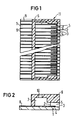
- the spray module 11 consists of a substrate 1 on which ink channels and heating resistors assigned to them are formed.
- the ink channels 5 can be formed, for example, by dividers 2 and by the formation of a cover 6.
- the spray module 11 On the side facing a recording medium, the spray module 11 thus has a series of outlet openings or nozzles 3.
- the ink channels 5 are connected to a common ink chamber 7.
- each heating resistor 4 can be controlled from the outside via an individual contact connection 8 and a contact connection 9 common to all heating elements.
- the contact connections 8, 9 are preferably arranged in the form of conductor tracks on the substrate 1.
- the ink vapor bubble collapses very quickly, which on the one hand promotes the detachment of the ink droplet from the nozzle 3, and on the other hand leads to the suction of ink and thus to the refilling of the ink channel.
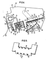
- FIG. 3 shows an ink printing unit in which a separation between the lower part of the ink printing unit and the actual print heads is realized.
- the ink printheads 12 are arranged in parallel in the writing line direction next to one another on the lower part of the ink printing unit and each contain a spray module 11 directed in the direction of a recording medium 20 and described with reference to FIGS. 1 and 2 Black is provided, of which only one, namely the foremost print head, is shown in the illustration according to FIG. 3.
- the axis identified by reference numeral 13 within the print head 12 marks the center of the text field, which can be printed with the spray module 11 during a line scan.
- the record carrier 20 is transported line by line by a platen roller 19 and serves during of writing as a counterpart.
- the printing unit can be moved back and forth in the line direction in front of the recording medium 20 on guide rods 21, 22 in a manner not shown here.
- the ink reservoirs 15, 16 are accommodated, each with a device monitoring the fill level, the electrical connections, of which only one ribbon cable 17 is shown in FIG.
- two ink supply containers are provided, one of which is filled with the color black and the other container contains the three primary colors yellow, magenta red and cyan blue in three separate bottles.
- One or more ink printheads 12 can be plugged and locked into the lower part 18 of the printing unit and are easily exchangeable by the user of the ink printing device.
- the exchangeable ink print head 12 essentially consists of a carrier plate 23, preferably made of aluminum, with a glued-on spray module 11, an ink supply with a hollow needle 24 for the fluid mechanical coupling and a printed circuit board with a conductive foil 32 for the electrical connection.
- the carrier plate is designed as a pluggable unit in such a way that guide and locking elements of the lower part 18 of the printing unit come into direct contact with it.
- Lugs 37, 38 having a rectangular shape are formed, which are inserted into corresponding recesses in a head guide 34, which is realized as a plastic injection-molded part, and then locked.
- connection pieces 41 in the form of sleeves for receiving the hollow needles 24 are provided on the head guide 34.
- the sleeves 41 are covered at the entry points for the hollow needles 24 with a cap 26 made of rubber-elastic material, for example an elastomer.
- caps are attached to the free end of the sleeves and encompass the free end of the sleeves in the manner of a union nut.
- hose pieces can be pushed on, which lead to the ink supply containers.
- the upper side of the corresponding cap 26 is pierced by the hollow needle 24 belonging to the ink supply and the fluid-mechanical connection is established with the ink supply containers.
- a ring made of metallic material pressed onto the individual caps 26 prevents any leaks even with removed ink print heads and thus hollow needles 24.
- the hollow needles 24 lead on the carrier plates 23 to the spray modules 11, where they pass through a glass cover plate into an ink chamber flows.
- the reference numeral 36 designates a sealing ring which seals the connection point of the ink feed with the ink chamber.
- the printing unit lower part 18 has a comb-like guide element 35 on the end face facing the recording medium in addition to the head guide 34 (FIG. 5).
- this comb part which is preferably implemented as a metal stamped and bent part , receiving slots with funnel-shaped insertion bevels are provided on the upper edge and on the lower end bent at an obtuse angle counter to the ejection direction of the injection module.
- One receiving slot each at the upper and lower ends of the comb part serve to guide a carrier plate 23.
- FIG. 5 shows a comb part for a printing unit with four pairs of receiving slots, ie for ink print heads on four individual carrier plates.
- the head guide 34 has an upwardly raised wall 42, on the upper edge of which, likewise in the sectional view according to FIG. 4, shaped receiving slots corresponding to the receiving slots in the comb part 35 are formed.
- the width 43 of the receiving slots 39, 40 is adapted to the thickness of the carrier plates 23 present in the corresponding insertion area and is identical for all receiving slots, so that the individual carrier plates and thus the individual printheads can be exchanged among one another within the existing slots.
- the parts for the electrical coupling and for locking the ink print heads are also arranged in the head guide 34.
- the electrical connection of the thermal converter of the spray module 11 takes place via a conductor foil 32 running on the carrier plate 23 and is contacted when a plug-in and locking of the ink print heads is carried out with a connecting line 17 leading to the central control of the writing device and common to all ink print heads.
- the conductor foil 32 has raised contact pads in the connection area, which are pressed onto corresponding contact points of the connection line 17.
- a strip made of a rubber-elastic material 33, for example made of elastomer, is embedded in the head guide 34 as a counter bearing. In conjunction with the raised contact pads on the conductor foil, this elastomeric pressure element 33 ensures the necessary contact security.
- Centering pins 43 in the head receptacle 34 allow a precise assignment the connecting line 17 to the individual ink print heads 12.
- a pawl 29 is used for the mechanical locking of the ink print heads 12 inserted into the head guide 34 and into the guide comb 35, which pawl can be snapped into a notched recess in the shoulder 38 of the carrier plate 23.
- the pawl 29 is pivotably arranged on a lever 44 mounted on one side on the printing unit lower part 18 by means of an axis 45.
- the end of a leaf spring 27 is clamped in the pawl 29 above its fulcrum, the free end of which leads via the lever 44 in the direction of a locking lever 31 arranged on the side of the printing unit.
- the locking lever 31 is pivotally mounted on the printing unit lower part 18 on an axis 46.
- a cam 28 which is firmly connected to it and is common to all ink print heads, is formed on which the leaf springs 27 rest.
- a nose-like projection 47 is provided on the lever 44 carrying the pawl 29, which ensures that the leaf spring 27 does not deflect upwards when the ink printheads are locked and the pivoting movement of the locking lever 31 via the leaf spring 27 is reliably transmitted to the pawl 29.
- a pawl 29 is provided for each pluggable ink printhead, which is pressed into the latching recess of the corresponding extension 38 via a leaf spring 27 each. It is thereby achieved that the locking force of the individual ink print heads is independent of one another for all ink print heads despite a single locking lever with a common cam.
- the projections 37 and 38 projecting from the carrier plate in the plugging direction enter the corresponding receptacles of the head guide 34 and take on a rough demonstration.
- the hollow needle 24 of the ink supply system already pierces the elastic cap 26 during this rough guidance Design tolerates a possibly occurring center offset and reliably seals the connection point in any case.
- the insertion bevels both on the head guide 34 and on the comb 35 facilitate the transition from the rough guide into the precise assignment of the carrier plates to the lower part of the printing unit and thus also the position of the printing heads.
- the comb with its finely punched receiving slots 39, 40 takes over the guidance and positions the carrier plates in the correct position.
- a leaf spring 30 is provided for each ink print head 12 in the area of the attachment 37 between the contact points A and B. This leaf spring compensates for the play occurring perpendicular to the plane of the drawing and is designed so that it only presses laterally against the support plate 23 at the end of the plugging process, so that the lateral force thereby generated does not have to be overcome during the entire plugging process.
- the locking lever 31 is pivoted clockwise. This also rotates the common cam 28 in the same direction and tensions the leaf spring 27.
Landscapes
- Ink Jet (AREA)
Abstract
Claims (12)
- Unité d'impression à encre pour des dispositifs d'écriture à encre, comportant plusieurs têtes d'impression à encre (12) agencées de façon interchangeable, pour représenter des signes et/ou des modèles graphiques en une et/ou plusieurs couleurs, qui peut être déplacée en va-et- vient dans la direction des lignes d'écriture le long d'un support d'enregistrement (20),
caractérisée en ce que les têtes d'impression à encre (12) sont agencées, à chaque fois, sur des plaques de support individuelles (23) de construction identique, et peuvent être enfichées dans un sous-ensemble (18) de l'unité d'impression recevant les têtes d'impression à encre (12), et des moyens pour le couplage mécanique, électrique et fluido-mécanique (27,28,29,31,26,41,33) des têtes d'impression à encre individuelles (12) au sous-ensemble (18) de l'unité d'impression sont prévus de sorte que le processus de couplage est effectué automatiquement pendant l'enfichage des têtes d'impression à encre (12) dans le sous-ensemble (18) de l'unité d'impression. - Unité d'impression à encre selon la revendication 1, caractérisée en ce que les plaques de support (23) sont agencées parallèlement dans la direction des lignes d'écriture les unes à côté des autres.
- Unité d'impression à encre selon la revendication 1, caractérisée en ce que les emplacements d'enfichage pour les plaques de support individuelles (23) dans le sous-ensemble (18) de l'unité d'impression sont réalisés de façon identique.
- Unité d'impression à encre selon la revendication 1 ou 2, caractérisée en ce que le couplage mécanique des têtes d'impression à encre (12) est effectué par l'intermédiaire d'éléments de guidage (34,35) et d'un dispositif de verrouillage (28,29,27,44,31), lequel bloque les têtes d'impression à encre (12) dans l'état enfiché au moyen d'éléments d'encliquetage et de verrouillage (29,38,28,31).
- Unité d'impression à encre selon la revendication 4, caractérisée en ce que les dispositifs de verrouillage comportent un levier pivotant (44) à cliquet (29), agencé sur celui-ci, pouvant de même pivoter par rapport au levier (44), cliquet qui est pressé dans des évidements d'encliquetage de la plaque de support (23) par l'intermédiaire d'un ressort à lames (27) et d'un levier de verrouillage (31) pouvant être actionné manuellement, à came (28) associée.
- Unité d'impression à encre selon la revendication 5, caractérisée en ce que, pour le verrouillage de toutes les têtes d'impression à encre (12), un seul levier de verrouillage (31) avec une came commune (28) est prévu, qui agit sur des ressorts à lames (27) et des cliquets (29) individuels associés aux têtes d'impression à encre individuelles (12), de sorte que les forces de verrouillage des têtes d'impression à encre individuelles (12) sont indépendantes les unes des autres.
- Unité d'impression à encre selon la revendication 1, caractérisée en ce que, pour le couplage électrique d'une feuille conductrice (32) menant aux têtes d'impression à encre individuelles (12) sur la plaque de support (23) avec un conducteur à bande plate (17) commun à toutes les têtes d'impression à encre (12) et menant à la commande du dispositif d'écriture, les parties de raccordement respectives des conducteurs sont pressées les unes sur les autres lors du processus de verrouillage.
- Unité d'impression à encre selon la revendication 7, caractérisée en ce que le conducteur à bande plate (17) dans la zone de contact est associé, par l'intermédiaire d'éléments de centrage (43), aux têtes d'impression à encre individuelles (12), et, en tant que contre-butée de pression pour le processus de verrouillage, un élément de pressage élastique en caoutchouc (33) est prévu.
- Unité d'impression à encre selon la revendication 1, caractérisée en ce que, pour le couplage fluido-mécanique de la tête d'impression à encre (12) au sous-ensemble (18) de l'unité d'impression, une aiguille creuse (24), faisant saillie au-dessus du contour de la plaque de support (23) dans la direction d'enfichage de la plaque de support (23), est prévue, aiguille qui est reçue par un capuchon (26) en une matière élastique, agencé sur le sous-ensemble (18) de l'unité d'impression, et qui forme la liaison fluidique aux réservoirs d'encre (15,16) prévus de même dans le sous-ensemble (18) de l'unité d'impression.
- Unité d'impression à encre selon la revendication 9, caractérisée en ce que le capuchon (26) est enfiché sur une pièce de liaison (41) jouant le rôle d'un manchon et, sur son dessus, est pressée une bague métallique (25) qui empêche des fuites éventuelles lorsqu'une tête d'impression à encre (12) est retirée.
- Unité d'impression à encre selon la revendication 1, caractérisée en ce que les emplacements d'enfichage dans le sous-ensemble (18) de l'unité d'impression reçoivent des têtes d'impression à encre (12) pour l'impression en une et même encre.
- Unité d'impression à encre selon la revendication 1, caractérisée en ce que les emplacements d'enfichage dans le sous-ensemble (18) de l'unité d'impression reçoivent des têtes d'impression à encre (12) pour éjecter des encres différentes ou des tailles de gouttes différentes.
Applications Claiming Priority (2)
| Application Number | Priority Date | Filing Date | Title |
|---|---|---|---|
| EP89120145 | 1989-10-30 | ||
| EP89120145 | 1989-10-30 |
Publications (2)
| Publication Number | Publication Date |
|---|---|
| EP0500563A1 EP0500563A1 (fr) | 1992-09-02 |
| EP0500563B1 true EP0500563B1 (fr) | 1993-11-24 |
Family
ID=8202079
Family Applications (1)
| Application Number | Title | Priority Date | Filing Date |
|---|---|---|---|
| EP90915307A Expired - Lifetime EP0500563B1 (fr) | 1989-10-30 | 1990-09-24 | Imprimante a jet d'encre avec tetes d'impression interchangeables |
Country Status (4)
| Country | Link |
|---|---|
| EP (1) | EP0500563B1 (fr) |
| JP (1) | JPH05508357A (fr) |
| DE (1) | DE59003637D1 (fr) |
| WO (1) | WO1991006432A1 (fr) |
Families Citing this family (5)
| Publication number | Priority date | Publication date | Assignee | Title |
|---|---|---|---|---|
| DE4207623C2 (de) * | 1992-03-06 | 1998-08-27 | Eastman Kodak Co | Verfahren zum Drucken mit einem seriellen Tintenstrahldrucker |
| DE4309255A1 (de) * | 1993-03-16 | 1994-09-22 | Francotyp Postalia Gmbh | Modularer Tintenstrahldruckkopf |
| AU2304795A (en) * | 1994-04-21 | 1995-11-16 | Allan Vincent Andersen | A graphical printer system |
| US6260950B1 (en) | 1995-04-21 | 2001-07-17 | Canon Kabushiki Kaisha | Ink jet printing system using printers with interchangeable printing units |
| DE19651048C2 (de) * | 1996-12-09 | 2002-05-29 | Francotyp Postalia Gmbh | Anordnung für einen Tintendruckkopf |
Family Cites Families (5)
| Publication number | Priority date | Publication date | Assignee | Title |
|---|---|---|---|---|
| US4376283A (en) * | 1980-11-03 | 1983-03-08 | Exxon Research And Engineering Co. | Method and apparatus for using a disposable ink jet assembly in a facsimile system and the like |
| IT1179109B (it) * | 1984-09-10 | 1987-09-16 | Olivetti & Co Spa | Testina di stampa seriale a getto d'inchiostro |
| IT1182682B (it) * | 1985-11-14 | 1987-10-05 | Olivetti & Co Spa | Testina di stampa a getto d'inchiostro elettricamente conduttivo e relativo dispositivo di stampa |
| US4758849A (en) * | 1987-01-09 | 1988-07-19 | Eastman Kodak Company | Hand-held ink jet with insertable cartridges |
| CA1304983C (fr) * | 1987-10-23 | 1992-07-14 | David W. Pinkernell | Mecanisme de centrage et d'interconnexion electrique a verrouillage pour chariot de tete d'impression |
-
1990
- 1990-09-24 JP JP2514238A patent/JPH05508357A/ja active Pending
- 1990-09-24 EP EP90915307A patent/EP0500563B1/fr not_active Expired - Lifetime
- 1990-09-24 DE DE90915307T patent/DE59003637D1/de not_active Expired - Fee Related
- 1990-09-24 WO PCT/EP1990/001619 patent/WO1991006432A1/fr not_active Ceased
Non-Patent Citations (2)
| Title |
|---|
| PATENT ABSTRACTS OF JAPAN, vol. 10, no. 55, (M-458)(2112), 05.03.1986; JP A 60 204 340 * |
| PATENT ABSTRACTS OF JAPAN, vol. 10, no. 55, (M-458)(2112), 05.03.1986; JP A 60 204 342 * |
Also Published As
| Publication number | Publication date |
|---|---|
| EP0500563A1 (fr) | 1992-09-02 |
| DE59003637D1 (de) | 1994-01-05 |
| JPH05508357A (ja) | 1993-11-25 |
| WO1991006432A1 (fr) | 1991-05-16 |
Similar Documents
| Publication | Publication Date | Title |
|---|---|---|
| DE69216935T2 (de) | Instandsetzungsstelle für Farbstrahldrucker | |
| DE69800254T2 (de) | Auswechselbarer Druckkopfwartungsmodul mit mehreren Funktionen (wischen/abdecken/ausstossen/ansaugen) | |
| DE19522594C2 (de) | Vorrichtung zur Reinhaltung der Düsen eines Tintendruckkopfes | |
| DE69922759T2 (de) | Modulare Druckpatrone zur Anwendung in Tintenstrahldrucksystemen | |
| DE69723737T2 (de) | Tintenbehälter mit elektronischen und mechanischen merkmalen, der zwischen verschiedenen versorgungsgrössen steckerkompabilität erlaubt | |
| DE19534577C2 (de) | Tintenpatrone und Tintenstrahl-Aufzeichnungsgerät | |
| DE69800173T2 (de) | Optische Kodierung eines Wartungsmoduls für einen Druckkopf | |
| DE69809933T2 (de) | Verfahren und vorrichtung zur sicherung eines tintenbehälters | |
| EP0054694B1 (fr) | Tête d'impression pour imprimante à jet d'encre munie d'un chariot mobile par rapport à la ligne d'impression | |
| DE69417990T2 (de) | Paralleldrucker in modularer Struktur und sein Herstellungsverfahren | |
| DE3316474C2 (fr) | ||
| DE3853403T2 (de) | Drucker, versehen mit auswechselbaren und identifizierbaren Druckköpfen oder Stiften. | |
| DE3524000B4 (de) | Flüssigkeitsstrahlaufzeichnungskopf | |
| DE69402235T2 (de) | Inbetriebstellungsgerät für einen Tintenstrahldrucker | |
| DE69332186T2 (de) | Abnehmbare Tintenstrahleinheit und Farbstrahlaufzeichnungsgerät | |
| DE69729520T2 (de) | Verbindungsmethode für Tintenstrahlkopfeinheiten, Tintenstrahlkopfeinheit und Tintenkassette | |
| DE68914978T2 (de) | Tintenkassette und kassettenhalterung für einen mehrfarbig arbeitenden tintenstrahldrucker. | |
| DE69802126T2 (de) | Tintenzuführsystem für ein Tintenstrahldrucksystem | |
| DE60131687T2 (de) | Auswechselbarer Tintenbehälter für ein Tintenstrahldrucksystem | |
| DE3855082T2 (de) | Farbstrahlaufzeichnungsgerät mit Ablagenrückgewinnungsvorrichtung | |
| US5461405A (en) | Ink jet printer device with exchangeable printheads | |
| DE69225052T2 (de) | Tintenstrahlaufzeichungsmittel und zugehörige Verpackung | |
| DE3502901A1 (de) | Fluessigkeitsstrahl-aufzeichnungsgeraet | |
| DE69800381T2 (de) | Handauswechselbares Wartungsmodul für jeden einzelnen Tintenstrahldruckkopf | |
| EP0021389A1 (fr) | Dispositif d'impression à encre pour l'impression d'un support d'impression |
Legal Events
| Date | Code | Title | Description |
|---|---|---|---|
| PUAI | Public reference made under article 153(3) epc to a published international application that has entered the european phase |
Free format text: ORIGINAL CODE: 0009012 |
|
| 17P | Request for examination filed |
Effective date: 19920415 |
|
| AK | Designated contracting states |
Kind code of ref document: A1 Designated state(s): DE IT |
|
| 17Q | First examination report despatched |
Effective date: 19921214 |
|
| GRAA | (expected) grant |
Free format text: ORIGINAL CODE: 0009210 |
|
| AK | Designated contracting states |
Kind code of ref document: B1 Designated state(s): DE IT |
|
| PG25 | Lapsed in a contracting state [announced via postgrant information from national office to epo] |
Ref country code: IT Free format text: LAPSE BECAUSE OF FAILURE TO SUBMIT A TRANSLATION OF THE DESCRIPTION OR TO PAY THE FEE WITHIN THE PRE;WARNING: LAPSES OF ITALIAN PATENTS WITH EFFECTIVE DATE BEFORE 2007 MAY HAVE OCCURRED AT ANY TIME BEFORE 2007. THE CORRECT EFFECTIVE DATE MAY BE DIFFERENT FROM THE ONE RECORDED.SCRIBED TIME-LIMIT Effective date: 19931124 |
|
| REF | Corresponds to: |
Ref document number: 59003637 Country of ref document: DE Date of ref document: 19940105 |
|
| PLBE | No opposition filed within time limit |
Free format text: ORIGINAL CODE: 0009261 |
|
| STAA | Information on the status of an ep patent application or granted ep patent |
Free format text: STATUS: NO OPPOSITION FILED WITHIN TIME LIMIT |
|
| 26N | No opposition filed | ||
| PGFP | Annual fee paid to national office [announced via postgrant information from national office to epo] |
Ref country code: DE Payment date: 19950928 Year of fee payment: 6 |
|
| PG25 | Lapsed in a contracting state [announced via postgrant information from national office to epo] |
Ref country code: DE Effective date: 19970603 |